EP0484628B1 - Dispositif d'accouplement rapide d'une pièce à main dentaire - Google Patents
Dispositif d'accouplement rapide d'une pièce à main dentaire Download PDFInfo
- Publication number
- EP0484628B1 EP0484628B1 EP91110581A EP91110581A EP0484628B1 EP 0484628 B1 EP0484628 B1 EP 0484628B1 EP 91110581 A EP91110581 A EP 91110581A EP 91110581 A EP91110581 A EP 91110581A EP 0484628 B1 EP0484628 B1 EP 0484628B1
- Authority
- EP
- European Patent Office
- Prior art keywords
- sleeve
- coupling
- face
- sleeves
- tubes
- Prior art date
- Legal status (The legal status is an assumption and is not a legal conclusion. Google has not performed a legal analysis and makes no representation as to the accuracy of the status listed.)
- Expired - Lifetime
Links
Images

Classifications
-
- A—HUMAN NECESSITIES
- A61—MEDICAL OR VETERINARY SCIENCE; HYGIENE
- A61C—DENTISTRY; APPARATUS OR METHODS FOR ORAL OR DENTAL HYGIENE
- A61C1/00—Dental machines for boring or cutting ; General features of dental machines or apparatus, e.g. hand-piece design
- A61C1/08—Machine parts specially adapted for dentistry
- A61C1/18—Flexible shafts; Clutches or the like; Bearings or lubricating arrangements; Drives or transmissions
Definitions
- Turbine-driven dental handpieces are typically constructed so that they may be disconnected from their supply hoses when removal or replacement is desired.
- the connection is usually a threaded one with the operator either tightening or loosening a threaded coupling sleeve that brings the ported end face of a connector into or out of contact with a sealing gasket that surrounds a plurality of fluid supply tubes in the mating part.
- a gasket is depicted, for example, in co-owned patent 4,330,279 ( Figure 9) (See also US-A-4.403.959).
- an important aspect of this invention lies in providing a coupling that allows a handpiece to be quickly and easily connected or disconnected, with only a fractional turn of such a handpiece in relation to its hose coupling assembly, and at the same time insures the application of a reproducible seal with a sealing force of predetermined magnitude whenever such parts are joined together. Since the applied sealing force is not in the control of the dentist or other operator, dangers of over-tightening or under-tightening are eliminated and with them the problems of leakage they might cause. Since over-tightening cannot occur, the distortions, deformations, possible damage, and increased wear caused by such over-tightening are avoided.
- One aspect of this invention lies in the recognition that a bayonet-type lock might be ideally suited for a quick connect/disconnect coupling if the problems inherent in such a coupling were overcome primarily by spring-loading a connector body that makes sealing contact with the sealing gasket of a handpiece.
- spring-loading the connector body By spring-loading the connector body, the reverse axial travel or backing-off inherent in bayonet lock operation when coupling or latching is fully achieved are nullified.
- the result is a coupling that permits rapid attachment and detachment without the disadvantages that might be expected from a bayonet lock arrangement.
- the coupling of this invention includes a hose connector assembly having a cylindrical first sleeve adapted to be joined at one end to a hose containing a drive air conduit, a secondary air conduit, and a water conduit.
- a cylindrical connector body that is slidably mounted for axial movement between extended and retracted positions.
- the body has a smooth, hard distal end face and axially-extending passages through the body for communication with the conduits.
- Spring means in the first sleeve urges the body in a distal direction into its extended position, the spring means preferably taking the form of a helical compression spring of flat wire.
- the coupling also includes a dental handpiece having a handle with a proximal end providing a cylindrical second sleeve dimensioned for rotatable telescoping engagement with the first sleeve.
- One of the two sleeves is provided with a plurality of J-shaped bayonet slots and the other with a plurality of lugs receivable in the slots for releasably coupling the sleeves in telescoped condition.
- the handpiece includes a plurality of tubes that project from its proximal end and are receivable in the passages of the connector body. Sealing means in the form of a resilient gasket is mounted within the second sleeve and surrounds the tubes for sealingly engaging the end face of the connector body when the sleeves are coupled together.
- the gasket surrounds the tubes along a portion of their length and integral frusto-conical sealing ring portions extend around each of the tubes for sealing engagement with the end face of the connector body.
- a rigid support ring backs and surrounds the gasket to control deformation of the gasket material and insure sealing effectiveness.
- Figure 1 is an exploded perspective view illustrating major components of the coupling of this invention.
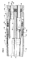
- Figure 2 is an enlarged vertical sectional view showing the hose connector assembly and the handpiece in separated condition.
- Figure 3 is a perspective view of the connector body.
- Figure 4 is an enlarged exploded perspective view of the sealing gasket and support ring.
- Figure 5 is an enlarged sectional view similar to Figure 2 but illustrating the parts in coupled condition.
- Handpiece 11 generally designates the combination of a dental handpiece 11 and a hose connector assembly 12. Except for features of the coupling mechanism described in detail hereinafter, the handpiece may be similar to that shown and described in co-owned patent 4,330,279, the disclosure of which is incorporated by reference herein.
- Handpiece 11 includes a handle 13 with an externally-threaded proximal end portion 13a.
- a plurality of tubes project longitudinally from the handle for conducting drive air, water, and light towards the handpiece's working end (not shown).
- tube 14 carries drive air to the turbine
- 15 transmits exhaust air back from the turbine
- 16 conveys water
- 17 carries secondary air for removing debris and producing a spray.
- Tube 18 contains a fiber optic conductor for transmitting light to the head of the handpiece.
- the hose connector assembly 12 includes a collar 19 joined to flexible hose 20. Through the hose and collar extend conduits 21 and 22 for conducting drive air and secondary air, respectively. Conduit 23 carries water and, if desired, a fiber optic cable may extend through the hose and collar to conduct light to waveguide 18 when the parts are assembled. alternatively, an electric lamp (not shown) may be mounted within the hose connector assembly 10, with wires leading through hose 20, for providing the necessary illumination.
- Collar 19 is connected to a cylindrical first sleeve 25 in a manner that permits independent rotation or swivel action between sleeve 25 and collar 19.
- distal end 19a of the collar is threadedly connected to a ring 26, the ring in turn being rotatably supported by an annular bearing 27 carried by sleeve 25.
- Locking ring 28 is received in an annular groove 29 in the collar and engages threaded ring 26 to prevent axial separation of the parts unless, of course, collar 19 is unthreaded from ring 26. The arrangement thus permits free rotation of sleeve 25 with respect to collar 19.
- first sleeve 25 Within first sleeve 25 is a cylindrical connector body 30 shown most clearly in Figures 2 and 3. Passages extend through that body for conducting air, water, and light, such passages communicating with the conduits extending through hose 20.
- Passage 31 carries drive air from conduit 21, the conduit being connected to a swivel fitting 32 supported in passage 31 in a manner that permits rotation of conduit 21 relative to connector body 30.
- Passage 33 communicates with water conduit 23, and passage 34 with secondary air conduit 22.
- the enlarged passage 35 conducts exhaust air through the body back into the hose 20. In the embodiment illustrated, passage 35 simply discharges into the empty space within hose 20 and does not communicate with a separate exhaust conduit within that hose.
- the connector body is longitudinally slidable within first sleeve 25 between an extended position shown in Figure 2 and a retracted position depicted in Figure 5.
- a helical compression spring 36 extends about the midportion of the connector body within sleeve 25 and urges the body in a distal direction (towards the right as viewed in Figure 2).
- Split ring 37 received in an internal groove within sleeve 25, engages an external shoulder 38 of the connector body to limit the extension of that body.
- the spring 36 has coils of flat wire that appear rectangular rather than circular in section; such a spring is believed to exert greater and more uniform force for the space it occupies and the extent of dimensional changes that occur when the body is shifted between its extended and retracted positions than a spring with wire of circular section.
- body 30 terminates in a planar end face 40.
- the face should be smooth and hard to provide a durabel, scratch-resistant sealing surface. If the connector body 30 is formed of aluminum, the surfaces of the body, particularly end face 40, are preferably anodized to increase surface hardness and smoothness.
- a generally cylindrical second sleeve 42 is threaded onto the proximal end portion 13a of handpiece handle 13 and constitutes an extension of that handle.
- a resilient disk-shaped gasket 43 formed of natural or synthetic rubber.
- the gasket has openings 44, 45, 46, 47 and 48 that respectively receive tubes 15, 14, 16, 17 and 18 of the handpiece.
- the gasket surrounds a portion of each tube and is supported by a rigid cup or support ring 49 received within sleeve 42.
- the cup or support ring has an annular side wall 50 that confines the periphery of gasket 49 and an end wall 51 that prevents distal displacement of the gasket. Apertures 51a in the end wall receive the tubes 14-18, such apertures being aligned with openings 44-48 in the gasket. If desired, the gasket may he adhesively secured within support ring 49.
- those openings in the gasket that receive fluid-carrying tubes have integral frusto-conical sealing ring portions or protuberances 44a, 45a, 46a, and 47a.
- the frusto-conical surfaces of such sealing ring portions are sealingly engagable with the end face 40 of connector body 30 at the openings for passages 31, 33, 34 and 35. Because the gasket 43 is confined by support ring 49, compressive deformations of the gasket are controlled, predictable, and reproducible, insuring effective sealing action between the parts over periods of extended use and many coupling/uncoupling operations.
- first and second sleeves 25 and 42 are dimensioned to telescope together as shown in Figure 5.
- second sleeve 42 has a reduced cylindrical proximal end portion 42a receivable in open distal end of first sleeve 25.
- Latching is achieved by means of a plurality of internal lugs 55 that project radially inwardly from the inner surface of the sleeve 25 at uniformly circumferentially-spaced points.
- the lugs are received in J-shaped slots 56 formed in the end of reduced sleeve portion 42a.
- the provision of a plurality of equally-spaced slots and lugs is believed important in achieving control, reproducible compression of gasket 43 when the parts are joined together. While the preferred number of mating slots and lugs is three, it is believed that under some circumstances a greater or smaller number might be provided.
- connector body 30 When the handpiece and hose connector assembly are coupled together as shown in Figure 5, connector body 30 is partially retracted.
- the sealing force applied by the body 30 against gasket 43 is generated solely by compression spring 36. Since the force of that spring may be controlled within narrow limits, a substantially constant sealing force is applied to prevent fluid leakage regardless of the number of times the parts are coupled and uncoupled and notwithstanding the fact that during a coupling operation, as lugs 55 travel into slots 56, the parts first advance axially towards each other and then retract or back off slightly.
- gasket 43 should be formed of an elastomeric material having a durometer measurement within the range of about 50 to 75 on the Shore A scale. Particularly effective results have been achieved using an elastomeric gasket having a durometer within the range of 60 to 70. With such a gasket, effective sealing has been found to occur if spring 36 exerts an axial force as low as 1.5 pounds although in actual practice a spring exerting greater force (for example, 4.5 pounds) is preferred in order to provide a substantial margin of protection against leakeage.
Landscapes
- Health & Medical Sciences (AREA)
- Oral & Maxillofacial Surgery (AREA)
- Dentistry (AREA)
- Epidemiology (AREA)
- Life Sciences & Earth Sciences (AREA)
- Animal Behavior & Ethology (AREA)
- General Health & Medical Sciences (AREA)
- Public Health (AREA)
- Veterinary Medicine (AREA)
- Dental Tools And Instruments Or Auxiliary Dental Instruments (AREA)
Claims (11)
- Accouplement à connexion et déconnexion rapides pour pièces à main dentaires, comportant un ensemble de connecteur à tube flexible (20) comprenant un premier manchon généralement cylindrique (25) ayant une extrémité distale ouverte et une extrémité proximale adaptée pour être connectée à un tube flexible contenant un conduit d'air d'entraînement (14), un conduit d'air secondaire (17) et un conduit d'eau (16) ; un corps de connecteur généralement cylindrique (30) monté télescopique dans ledit premier manchon permettant un déplacement axial limité entre des positions en extension et rétractée; ledit corps comprenant une face d'extrémité distale (40) et ayant des passages s'étendant dans une direction axiale à travers ledit corps pour mettre en communication lesdits conduits ; un moyen de ressort (36) logé dans ledit premier manchon pour pousser ledit corps dans une direction distale dans ladite position en extension ; une pièce à main dentaire (11) munie d'une poignée (13) ayant une extrémité proximale comprenant un deuxième manchon cylindrique (42) dimensionné en vue de son engagement télescopique avec ledit premier manchon ; caractérisé en ce qu'un desdits manchons comporte une pluralité d'encoches à baïonnette en forme de J, l'autre desdits manchons comportant une pluralité d'ergots pouvant être reçus dans lesdites encoches en vue de l'accouplement et du désaccouplement desdits manchons ; ladite pièce à main comprenant une pluralité de tubes (14, 16, 17) formant saillie depuis ladite extrémité proximale et pouvant être reçus dans lesdits passages dudit corps ; des moyen de joint élastique (43) montés à l'intérieur dudit deuxième manchon et entourant lesdits tubes afin d'assurer un engagement étanche de ladite face d'extrémité (40) dudit corps, et poussant ledit corps en position partiellement rétractée lorsque lesdits manchons sont accouplés l'un à l'autre ; grâce à quoi lesdits moyens de ressort (36) sont partiellement comprimés lorsque lesdits manchons sont accouplés afin d'exercer un effort prédéterminé pour maintenir l'engagement étanche entre ladite face d'extrémité et ledit joint.
- Accouplement selon la revendication 1, dans lequel ladite face d'extrémité dudit corps est dure, polie et plate.
- Accouplement selon la revendication 2, dans lequel ledit corps de connecteur est en aluminium et ladite face d'extrémité est anodisée.
- Accouplement selon la revendication 1, dans lequel lesdits moyens de joint élastique comportent un disque formant joint élastique comprenant des ouvertures à ajustage doux pour recevoir lesdits tubes ; ledit disque comprenant des portions de bagues d'étanchéité tronconiques intégrées s'étendant autour d'au moins certains desdits tubes en vue d'un engagement étanche avec ladite face d'extrémité dudit corps.
- Accouplement selon la revendication 4, dans lequel lesdits moyens de joint élastique comportent une bague support rigide comprenant une paroi latérale cylindrique entourant ledit disque et en prise avec celui-ci suivant un ajustage doux.
- Accouplement selon la revendication 5, dans lequel ladite bague support rigide comporte en outre une paroi d'extrémité servant d'appui audit disque ; ladite paroi d'extrémité comportant des ouvertures pour recevoir lesdits tubes.
- Accouplement selon la revendication 1, dans lequel lesdits moyens de ressort sont un ressort à compression hélicoïdal.
- Accouplement selon la revendication 7, dans lequel ledit ressort à compression hélicoïdal est constitué par du fil plat.
- Accouplement selon la revendication 1, dans lequel ledit premier manchon comporte des moyens à connexion pivotante pour connecter en rotation ledit premier manchon et le corps du connecteur qui y est contenu à un tube flexible de pièce à main.
- Accouplement selon la revendication 1, dans lequel un desdits manchons comporte trois desdites encoches en forme de J, l'autre desdits manchons comportant trois desdits ergots ; lesdits ergots et lesdites encoches étant respectivement équidistants dans une direction circonférentielle.
- Accouplement selon la revendication 10, dans lequel l'un desdits manchons est désigné par premier manchon et l'autre desdits manchons est désigné par deuxième manchon.
Applications Claiming Priority (2)
| Application Number | Priority Date | Filing Date | Title |
|---|---|---|---|
| US608724 | 1990-11-05 | ||
| US07/608,724 US5039304A (en) | 1990-11-05 | 1990-11-05 | Quick connect/disconnect coupling for dental handpieces |
Publications (2)
| Publication Number | Publication Date |
|---|---|
| EP0484628A1 EP0484628A1 (fr) | 1992-05-13 |
| EP0484628B1 true EP0484628B1 (fr) | 1995-05-24 |
Family
ID=24437725
Family Applications (1)
| Application Number | Title | Priority Date | Filing Date |
|---|---|---|---|
| EP91110581A Expired - Lifetime EP0484628B1 (fr) | 1990-11-05 | 1991-06-26 | Dispositif d'accouplement rapide d'une pièce à main dentaire |
Country Status (5)
| Country | Link |
|---|---|
| US (1) | US5039304A (fr) |
| EP (1) | EP0484628B1 (fr) |
| JP (1) | JPH0685785B2 (fr) |
| CA (1) | CA2044430C (fr) |
| DE (1) | DE69110004T2 (fr) |
Families Citing this family (30)
| Publication number | Priority date | Publication date | Assignee | Title |
|---|---|---|---|---|
| US5586977A (en) * | 1990-01-26 | 1996-12-24 | C.R. Bard, Inc. | Quick disconnect fitting for coupling interchangeable probe tip to laparoscopic instrument |
| AT396742B (de) * | 1991-09-13 | 1993-11-25 | Intec Innovative Med Tech | Zahnärztliches handstück |
| DE4138673C1 (fr) * | 1991-11-25 | 1993-03-11 | Kaltenbach & Voigt Gmbh & Co, 7950 Biberach, De | |
| DE59309795D1 (de) * | 1992-10-22 | 1999-10-28 | Kaltenbach & Voigt | Vorrichtung zum Reinigen und Pflegen von ärztlichen oder zahnärtzlichen Instrumenten |
| FR2709658B1 (fr) * | 1993-02-19 | 1995-10-06 | Micro Mega Sa | Dispositif à douille d'accrochage pour raccordement rapide entre appareillages de dentisterie. |
| US5716210A (en) * | 1993-12-29 | 1998-02-10 | Dentsply Research & Development Corp. | Disposable filter for dental handpiece |
| US5501596A (en) * | 1994-07-27 | 1996-03-26 | Young Dental Manufacturing Company, Inc. | Autoclavable dental scaler handpiece |
| US5511977A (en) * | 1994-10-24 | 1996-04-30 | Futch, Jr.; Walter B. | Method for converting dental handpieces to quick disconnect |
| JP3040639U (ja) * | 1997-02-17 | 1997-08-26 | 株式会社ナカニシ | 歯科用ホースのハンドピース側端部構造 |
| US6149430A (en) * | 1998-02-20 | 2000-11-21 | Ora Innovations, Inc. | Integrally molded dental appliance and process for its manufacture |
| US6406470B1 (en) | 2000-02-22 | 2002-06-18 | Atc Technologies, Inc. | Surgical probe and value assembly and threaded quick disconnect adapter for use therewith |
| US6270344B1 (en) * | 2000-06-23 | 2001-08-07 | Ultradent Products, Inc. | Dental handpiece tubing coupler and related systems |
| US6716028B2 (en) | 2000-08-04 | 2004-04-06 | Hu-Friedy Mfg. Co., Inc. | Ultrasonic swivel insert |
| USD450845S1 (en) | 2000-12-15 | 2001-11-20 | Kinetic Instruments, Inc. | Bulkhead end of dental handpiece tubing with electric power for fiber optic capability |
| US6811399B2 (en) | 2001-07-27 | 2004-11-02 | Hu-Friedy Mfg. Co., Inc. | Torque lock for ultrasonic swivelable inserts and method |
| US7217128B2 (en) * | 2002-12-12 | 2007-05-15 | Discus Dental Impressions, Inc. | Ultrasonic dental insert having interchangeable plastic and metal tips |
| KR20060082031A (ko) * | 2002-12-12 | 2006-07-14 | 디스커스 덴탈 임프레션스 인코포레이티드 | 회전 가능한 헤드를 갖는 치과용 초음파 핸드피스 |
| US7530809B2 (en) * | 2002-12-12 | 2009-05-12 | Discus Dental, Llc | Ultrasonic dental handpiece having a rotatable head |
| NL1025397C2 (nl) * | 2004-02-04 | 2005-08-08 | Okey Holding B V | Tandheelkundige behandelinrichting. |
| US7431346B2 (en) | 2005-11-21 | 2008-10-07 | Campbell Hausfeld/Scott Fetzer Company | Quick connect coupling |
| EP2373249B1 (fr) | 2008-12-30 | 2018-04-11 | Ultradent Products, Inc. | Lampe de polymérisation à usage dentaire à conception unicorps servant de dissipateur thermique |
| JP5785777B2 (ja) * | 2011-05-19 | 2015-09-30 | 株式会社モリタ製作所 | 診療用インスツルメント |
| KR200470405Y1 (ko) * | 2012-04-24 | 2013-12-11 | 주식회사 세양 | 치과용 핸드피스 |
| CN104449020B (zh) | 2013-09-20 | 2019-01-11 | 陶氏环球技术有限公司 | 用于涂料组合物的反应性多官能添加剂 |
| USD721436S1 (en) * | 2013-10-09 | 2015-01-20 | Handpiece Club LLC | Self-aligning insert for a dental handpiece |
| US10285776B1 (en) * | 2016-02-23 | 2019-05-14 | Michael Feldman | Unitary cordless dental drive apparatus |
| US10702360B2 (en) * | 2016-07-07 | 2020-07-07 | Artyom GHAZARYAN | Filter unit for suction systems of dental equipment |
| US10883641B2 (en) * | 2018-03-30 | 2021-01-05 | Vittorio BONOMI | Quick disconnect coupling |
| CN113288479B (zh) * | 2021-05-26 | 2022-05-06 | 西安交通大学口腔医院 | 一种口腔修复科金属桩钉拆除装置 |
| CN116421315B (zh) * | 2023-06-14 | 2023-09-05 | 中南大学 | 一种连接装置及手术导航系统 |
Family Cites Families (7)
| Publication number | Priority date | Publication date | Assignee | Title |
|---|---|---|---|---|
| US2701147A (en) * | 1949-02-26 | 1955-02-01 | Aeromat Products Company Inc | Quick-release conduit connection |
| US3955284A (en) * | 1975-01-02 | 1976-05-11 | Balson John E | Disposable dental drill assembly |
| AT370611B (de) * | 1978-03-09 | 1983-04-25 | Siemens Ag | Zahnaerztliches handstueck |
| US4382790A (en) * | 1979-09-19 | 1983-05-10 | Kaltenbach & Voight Gmbh & Co. | Dental handpiece |
| US4330279A (en) * | 1980-01-07 | 1982-05-18 | American Hospital Supply Corporation | Fluid spray system for dental handpiece |
| US4403959A (en) * | 1981-07-31 | 1983-09-13 | Kabushiki Kaisha Yoshida Seisakusho | Coupling device for a dental instrument |
| AT389633B (de) * | 1986-10-07 | 1990-01-10 | Buermoos Dentalwerk | Anschlussteil fuer austauschbare griffhuelsen zahnaerztlicher handstuecke |
-
1990
- 1990-11-05 US US07/608,724 patent/US5039304A/en not_active Expired - Lifetime
-
1991
- 1991-06-12 CA CA002044430A patent/CA2044430C/fr not_active Expired - Lifetime
- 1991-06-26 EP EP91110581A patent/EP0484628B1/fr not_active Expired - Lifetime
- 1991-06-26 DE DE69110004T patent/DE69110004T2/de not_active Expired - Lifetime
- 1991-10-30 JP JP3285024A patent/JPH0685785B2/ja not_active Expired - Lifetime
Also Published As
| Publication number | Publication date |
|---|---|
| DE69110004T2 (de) | 1995-10-05 |
| DE69110004D1 (de) | 1995-06-29 |
| CA2044430A1 (fr) | 1992-05-06 |
| US5039304A (en) | 1991-08-13 |
| EP0484628A1 (fr) | 1992-05-13 |
| JPH04282150A (ja) | 1992-10-07 |
| CA2044430C (fr) | 1999-08-24 |
| JPH0685785B2 (ja) | 1994-11-02 |
Similar Documents
| Publication | Publication Date | Title |
|---|---|---|
| EP0484628B1 (fr) | Dispositif d'accouplement rapide d'une pièce à main dentaire | |
| EP0454672B1 (fr) | Appareil dentaire | |
| US6319001B1 (en) | Fitting for dental syringe tip | |
| EP0661024B1 (fr) | Filtre jetable pour pièces à main dentaires | |
| JPH039689Y2 (fr) | ||
| US4646751A (en) | Biopsy forceps | |
| US4534732A (en) | Dental handpiece | |
| US5655906A (en) | Autoclavable dental sonic scaler | |
| US5713878A (en) | Hand tightenable high pressure connector | |
| US4514169A (en) | Dental handpiece | |
| JP2005131413A (ja) | コネクタアセンブリ | |
| WO1992014498A1 (fr) | Dispositif de fixation d'aiguille de seringue | |
| US6102695A (en) | Dentistry handpiece | |
| CA2654007A1 (fr) | Tuyau de connexion coude pour appareil dentaire | |
| US11944266B2 (en) | Endoscope | |
| US20010031442A1 (en) | Quick fit revolving connecting unit for connecting a dental instrument to a power supply | |
| AU6186790A (en) | A connector for a shower head | |
| CA2463885C (fr) | Connecteur de cable de piece a main dentaire modulaire ultrasonore et integre | |
| US20120189978A1 (en) | Ultrasonic dental insert and lighted handpiece assembly | |
| US4212640A (en) | Dental handpiece | |
| GB2213732A (en) | Disposable dental nosel | |
| US6033220A (en) | Multi-purpose revolving connecting assembly | |
| ES2160285T3 (es) | Acoplamiento rotativo para mangueras. | |
| CN215272592U (zh) | 内窥镜手柄 | |
| ATE220524T1 (de) | Zahnärztliche schlauchanordnung |
Legal Events
| Date | Code | Title | Description |
|---|---|---|---|
| PUAI | Public reference made under article 153(3) epc to a published international application that has entered the european phase |
Free format text: ORIGINAL CODE: 0009012 |
|
| AK | Designated contracting states |
Kind code of ref document: A1 Designated state(s): CH DE FR GB IT LI |
|
| 17P | Request for examination filed |
Effective date: 19921104 |
|
| 17Q | First examination report despatched |
Effective date: 19940712 |
|
| RAP1 | Party data changed (applicant data changed or rights of an application transferred) |
Owner name: DENTSPLY RESEARCH & DEVELOPMENT CORP. |
|
| GRAA | (expected) grant |
Free format text: ORIGINAL CODE: 0009210 |
|
| AK | Designated contracting states |
Kind code of ref document: B1 Designated state(s): CH DE FR GB IT LI |
|
| REF | Corresponds to: |
Ref document number: 69110004 Country of ref document: DE Date of ref document: 19950629 |
|
| ITF | It: translation for a ep patent filed | ||
| ET | Fr: translation filed | ||
| PLBQ | Unpublished change to opponent data |
Free format text: ORIGINAL CODE: EPIDOS OPPO |
|
| PLBI | Opposition filed |
Free format text: ORIGINAL CODE: 0009260 |
|
| PLBF | Reply of patent proprietor to notice(s) of opposition |
Free format text: ORIGINAL CODE: EPIDOS OBSO |
|
| 26 | Opposition filed |
Opponent name: KALTENBACH & VOIGT GMBH & CO. Effective date: 19960223 |
|
| PLBF | Reply of patent proprietor to notice(s) of opposition |
Free format text: ORIGINAL CODE: EPIDOS OBSO |
|
| PLBO | Opposition rejected |
Free format text: ORIGINAL CODE: EPIDOS REJO |
|
| PLBN | Opposition rejected |
Free format text: ORIGINAL CODE: 0009273 |
|
| STAA | Information on the status of an ep patent application or granted ep patent |
Free format text: STATUS: OPPOSITION REJECTED |
|
| 27O | Opposition rejected |
Effective date: 19981022 |
|
| REG | Reference to a national code |
Ref country code: CH Ref legal event code: NV Representative=s name: E. BLUM & CO. PATENTANWAELTE |
|
| REG | Reference to a national code |
Ref country code: GB Ref legal event code: IF02 |
|
| REG | Reference to a national code |
Ref country code: CH Ref legal event code: PFA Owner name: DENTSPLY RESEARCH AND DEVELOPMENT CORPORATION Free format text: DENTSPLY RESEARCH AND DEVELOPMENT CORPORATION#LAKEVIEW AND CLARKE AVENUE#MILFORD/DE (US) -TRANSFER TO- DENTSPLY RESEARCH AND DEVELOPMENT CORPORATION#LAKEVIEW AND CLARKE AVENUE#MILFORD/DE (US) |
|
| PGFP | Annual fee paid to national office [announced via postgrant information from national office to epo] |
Ref country code: FR Payment date: 20100630 Year of fee payment: 20 |
|
| PGFP | Annual fee paid to national office [announced via postgrant information from national office to epo] |
Ref country code: CH Payment date: 20100625 Year of fee payment: 20 |
|
| PGFP | Annual fee paid to national office [announced via postgrant information from national office to epo] |
Ref country code: IT Payment date: 20100628 Year of fee payment: 20 Ref country code: DE Payment date: 20100629 Year of fee payment: 20 Ref country code: GB Payment date: 20100625 Year of fee payment: 20 |
|
| REG | Reference to a national code |
Ref country code: DE Ref legal event code: R071 Ref document number: 69110004 Country of ref document: DE |
|
| REG | Reference to a national code |
Ref country code: DE Ref legal event code: R071 Ref document number: 69110004 Country of ref document: DE |
|
| REG | Reference to a national code |
Ref country code: CH Ref legal event code: PL |
|
| REG | Reference to a national code |
Ref country code: GB Ref legal event code: PE20 Expiry date: 20110625 |
|
| PG25 | Lapsed in a contracting state [announced via postgrant information from national office to epo] |
Ref country code: GB Free format text: LAPSE BECAUSE OF EXPIRATION OF PROTECTION Effective date: 20110625 |
|
| PG25 | Lapsed in a contracting state [announced via postgrant information from national office to epo] |
Ref country code: DE Free format text: LAPSE BECAUSE OF EXPIRATION OF PROTECTION Effective date: 20110627 |