EP0484645B1 - Verfahren und Systeme zur Identifizierung von Flüssigkeiten und Bestimmung der Strömung - Google Patents
Verfahren und Systeme zur Identifizierung von Flüssigkeiten und Bestimmung der Strömung Download PDFInfo
- Publication number
- EP0484645B1 EP0484645B1 EP91114677A EP91114677A EP0484645B1 EP 0484645 B1 EP0484645 B1 EP 0484645B1 EP 91114677 A EP91114677 A EP 91114677A EP 91114677 A EP91114677 A EP 91114677A EP 0484645 B1 EP0484645 B1 EP 0484645B1
- Authority
- EP
- European Patent Office
- Prior art keywords
- test
- fluid
- sensor
- conduit
- flow rate
- Prior art date
- Legal status (The legal status is an assumption and is not a legal conclusion. Google has not performed a legal analysis and makes no representation as to the accuracy of the status listed.)
- Expired - Lifetime
Links
- 239000012530 fluid Substances 0.000 title claims description 109
- 238000000034 method Methods 0.000 title claims description 26
- 238000012360 testing method Methods 0.000 claims description 79
- 238000010438 heat treatment Methods 0.000 claims description 35
- 238000012545 processing Methods 0.000 claims description 33
- 230000001419 dependent effect Effects 0.000 claims description 17
- 239000007789 gas Substances 0.000 description 66
- 230000006870 function Effects 0.000 description 18
- 239000001307 helium Substances 0.000 description 11
- 229910052734 helium Inorganic materials 0.000 description 11
- SWQJXJOGLNCZEY-UHFFFAOYSA-N helium atom Chemical compound [He] SWQJXJOGLNCZEY-UHFFFAOYSA-N 0.000 description 11
- 239000007788 liquid Substances 0.000 description 6
- UFHFLCQGNIYNRP-UHFFFAOYSA-N Hydrogen Chemical compound [H][H] UFHFLCQGNIYNRP-UHFFFAOYSA-N 0.000 description 5
- 230000008859 change Effects 0.000 description 4
- 239000001257 hydrogen Substances 0.000 description 4
- 229910052739 hydrogen Inorganic materials 0.000 description 4
- 230000004044 response Effects 0.000 description 4
- 230000000875 corresponding effect Effects 0.000 description 3
- 230000003247 decreasing effect Effects 0.000 description 3
- 238000011144 upstream manufacturing Methods 0.000 description 3
- XKRFYHLGVUSROY-UHFFFAOYSA-N Argon Chemical compound [Ar] XKRFYHLGVUSROY-UHFFFAOYSA-N 0.000 description 2
- CURLTUGMZLYLDI-UHFFFAOYSA-N Carbon dioxide Chemical compound O=C=O CURLTUGMZLYLDI-UHFFFAOYSA-N 0.000 description 2
- 238000011088 calibration curve Methods 0.000 description 2
- 238000004891 communication Methods 0.000 description 2
- 239000000463 material Substances 0.000 description 2
- 239000000203 mixture Substances 0.000 description 2
- 239000007787 solid Substances 0.000 description 2
- 239000000243 solution Substances 0.000 description 2
- 230000007480 spreading Effects 0.000 description 2
- MYMOFIZGZYHOMD-UHFFFAOYSA-N Dioxygen Chemical compound O=O MYMOFIZGZYHOMD-UHFFFAOYSA-N 0.000 description 1
- XUIMIQQOPSSXEZ-UHFFFAOYSA-N Silicon Chemical compound [Si] XUIMIQQOPSSXEZ-UHFFFAOYSA-N 0.000 description 1
- 230000003321 amplification Effects 0.000 description 1
- 238000004458 analytical method Methods 0.000 description 1
- 229910052786 argon Inorganic materials 0.000 description 1
- 238000003556 assay Methods 0.000 description 1
- 230000003190 augmentative effect Effects 0.000 description 1
- 230000008901 benefit Effects 0.000 description 1
- 239000003990 capacitor Substances 0.000 description 1
- 239000001569 carbon dioxide Substances 0.000 description 1
- 229910002092 carbon dioxide Inorganic materials 0.000 description 1
- 238000001816 cooling Methods 0.000 description 1
- 238000012937 correction Methods 0.000 description 1
- 230000002596 correlated effect Effects 0.000 description 1
- 230000007812 deficiency Effects 0.000 description 1
- 229910001873 dinitrogen Inorganic materials 0.000 description 1
- 229910001882 dioxygen Inorganic materials 0.000 description 1
- 230000000694 effects Effects 0.000 description 1
- 238000004401 flow injection analysis Methods 0.000 description 1
- 239000000446 fuel Substances 0.000 description 1
- -1 hydrogen Chemical compound 0.000 description 1
- 150000002431 hydrogen Chemical class 0.000 description 1
- 238000012994 industrial processing Methods 0.000 description 1
- IJGRMHOSHXDMSA-UHFFFAOYSA-N nitrogen Substances N#N IJGRMHOSHXDMSA-UHFFFAOYSA-N 0.000 description 1
- QJGQUHMNIGDVPM-UHFFFAOYSA-N nitrogen(.) Chemical compound [N] QJGQUHMNIGDVPM-UHFFFAOYSA-N 0.000 description 1
- 238000003199 nucleic acid amplification method Methods 0.000 description 1
- 238000000746 purification Methods 0.000 description 1
- 238000011160 research Methods 0.000 description 1
- 229910052710 silicon Inorganic materials 0.000 description 1
- 239000010703 silicon Substances 0.000 description 1
- 239000000126 substance Substances 0.000 description 1
- WFKWXMTUELFFGS-UHFFFAOYSA-N tungsten Chemical compound [W] WFKWXMTUELFFGS-UHFFFAOYSA-N 0.000 description 1
Images




Classifications
-
- G—PHYSICS
- G01—MEASURING; TESTING
- G01F—MEASURING VOLUME, VOLUME FLOW, MASS FLOW OR LIQUID LEVEL; METERING BY VOLUME
- G01F1/00—Measuring the volume flow or mass flow of fluid or fluent solid material wherein the fluid passes through a meter in a continuous flow
- G01F1/68—Measuring the volume flow or mass flow of fluid or fluent solid material wherein the fluid passes through a meter in a continuous flow by using thermal effects
- G01F1/684—Structural arrangements; Mounting of elements, e.g. in relation to fluid flow
- G01F1/6845—Micromachined devices
-
- G—PHYSICS
- G01—MEASURING; TESTING
- G01F—MEASURING VOLUME, VOLUME FLOW, MASS FLOW OR LIQUID LEVEL; METERING BY VOLUME
- G01F1/00—Measuring the volume flow or mass flow of fluid or fluent solid material wherein the fluid passes through a meter in a continuous flow
- G01F1/68—Measuring the volume flow or mass flow of fluid or fluent solid material wherein the fluid passes through a meter in a continuous flow by using thermal effects
- G01F1/696—Circuits therefor, e.g. constant-current flow meters
-
- G—PHYSICS
- G01—MEASURING; TESTING
- G01N—INVESTIGATING OR ANALYSING MATERIALS BY DETERMINING THEIR CHEMICAL OR PHYSICAL PROPERTIES
- G01N27/00—Investigating or analysing materials by the use of electric, electrochemical, or magnetic means
- G01N27/02—Investigating or analysing materials by the use of electric, electrochemical, or magnetic means by investigating impedance
- G01N27/04—Investigating or analysing materials by the use of electric, electrochemical, or magnetic means by investigating impedance by investigating resistance
- G01N27/14—Investigating or analysing materials by the use of electric, electrochemical, or magnetic means by investigating impedance by investigating resistance of an electrically-heated body in dependence upon change of temperature
- G01N27/18—Investigating or analysing materials by the use of electric, electrochemical, or magnetic means by investigating impedance by investigating resistance of an electrically-heated body in dependence upon change of temperature caused by changes in the thermal conductivity of a surrounding material to be tested
Definitions
- This invention relates to methods and systems for identifying fluids and determining fluid flow rates and, more particularly, to methods and systems for determining gas flow rates using a hot wire anemometer.
- Instruments which rely upon controlled fluid flow are commonly employed in a wide variety of applications, such as sample purification, chemical analysis, clinical assay, and industrial processing.
- Many instruments such as high pressure liquid chromatographs (HPLC), gas chromatographs (GC), clinical analyzers, and flow-injection analyzers, require precisely-controlled flow.
- hot wire anemometers One major drawback of hot wire anemometers is the nonlinear and fluid-dependent manner in which they respond to fluid flow. Thus, the output signal is rarely useful by itself and must typically be augmented by other data. For applications wherein multiple gases are employed, both gas type information and the calibration curves corresponding to each of the different gases are necessary to determine the flow rate. A computer can be used to linearize or calculate flow rate from calibration curves. However, gas type information must first be fed into the computer in order to do so. Data processing in this manner requires initial identification of the gas and the performance of time-consuming data input steps.
- FR-A-2374639 discloses a method for determining the identity of a fluid essentially comprising the steps of arranging a heater in a test fluid, feeding such a power to the heater that its temperature is maintained at a predetermined value, generating a output signal indicative of the required heating power, and deriving the identity of the unknown fluid therefrom.
- EP-A-0373965 discloses a system for determining the flow rate of a fluid having a conduit comprising a first anemometer sensor for determining the fluid mass flow through the conduit. Further, the prior art system comprises a cavity in which a second anemometer sensor is arranged which is used as a thermal conductivity detector for obtaining a sensor output at a zero flow rate. A corrected mass flow is obtained from both sensor outputs.
- a thermal conductivity detector arranged in an area where fluid is relatively stationary is used for determining a correction factor which can be regarded as a nulled mass flow which is used for correcting the output of the first anemometer sensor arranged in the conduit.
- US-A-4475388 describes a system for measuring the flow rate of a fluid using four different coils.
- One heating coil is used to provide energy to the thermal system.
- Two of the coils are used to measure temperature differences due to gas flow.
- a fourth coil is used to measure the temperature of a fuel mixture.
- the present invention provides a method and system for determining the flow rate of a fluid, as defined in claims 1 and 8.
- Figure 1 depicts a fluid identification system according to the present invention.
- Figure 2a is a perspective view of a conduit according to the present invention, wherein the front portion thereof has been omitted.
- Figure 2b is a cross-sectional view of a conduit according to the present invention.
- Figure 3 depicts a flow determination system according to the present invention.
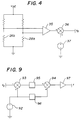
- Figure 4 depicts a circuit useful in a flow determination system according to the present invention.
- Figure 9 depicts a processing means according to the present invention.
- Fluids include gases, liquids, supercritical fluids, plastic solids, multiple component gases and liquids, and mixtures of solids and liquids capable of flow. Gases are preferred fluids according to the present invention.
- conduit encompasses any tube, pipe, or other vessel having the capacity to substantially contain and direct the flow of the fluid passed therethrough.
- Preferred conduits are fabricated from a wide variety of materials having at least minimal thermal conductivity.
- Conduits according to the present invention comprise a heating means substantially contained within the conduit.
- the heating means may be any of those known in the art.
- Preferred heating means comprise electrically resistive materials.
- a voltage source is preferably coupled with the heating means. Any of the wide variety of voltage sources known in the art are suitable for employment in the present invention, so long as they are capable of providing an input voltage to the heating means in order to maintain the heating means at a predetermined temperature. It is preferred that the predetermined temperature be greater than the temperature of the conduit, more preferably greater than the inside wall of the conduit. Preferred voltage sources are capable of providing a variable voltage to the heating means to maintain the predetermined temperature.
- Preferred fluid identification systems further comprise processing means coupled with both the voltage source and the output means.
- Processing means amenable to the practice of this invention consist of a computing device such a microprocessor, microcontroller, capacitor, switch, logic gate, or any equivalent logic device capable of compiling and executing instructions.
- Processing means preferably are coupled with a data input means such as a keyboard and a data output means such as a video display or printer.
- Preferred processing means further include one or more devices for the storage of data, such as magnetic disks or tape.
- Processing means preferably also comprise an operating system or programming environment for the generation of source code in the appropriate programming language, along with a compiler or other means of converting such source code into executable programs.
- FIG. 1 One preferred fluid identification system is depicted in Figure 1.
- This system comprises a fluid source (10) having metering means (12) for increasing or decreasing the flow rate of the fluid.
- the metering means may be any of those known in the art, such as valves, nozzles, and needles.
- a preferred fluid source is a canister which comprises pressurized gas.
- the fluid source is placed in fluid communication with a conduit (20) by way of tubing, piping, or some other suitable means (14) for transporting the fluid to the conduit.
- Preferred conduits according the present invention are depicted in Figures 2a and 2b.
- the conduit of Figure 2b is commercially-available from the MicroSwitch Company of Freeport, IL.
- Conduits useful for fluid identification comprise a heating means (24a or 24b).
- Preferred fluid identification systems further comprise a voltage source (32) coupled with the heating means and with a processing means (40) which is, in turn, coupled with a data output means (44) and a data input means
- Methods for determining the identity of test fluids in systems such as described above comprise passing the test fluid through the conduit. This is typically accomplished by opening a valve on a gas cylinder connected with the conduit. A test input voltage is then applied to the heating means in order to maintain the heating means at a temperature greater than the temperature of the conduit in the presence of the test fluid.
- a data set comprising the test input voltage is next provided to the processing means.
- the processing means comprises at least one reference input voltage.
- a reference input voltage is the input voltage required to maintain the heating means at a temperature greater than the temperature of the conduit in the presence of a reference fluid at a zero flow rate.
- Reference input voltages are preferably compiled by passing the reference fluid through the conduit, terminating passage of the reference fluid, applying a reference input voltage to the heating means, and recording the reference input voltage.
- the test input voltage is then compared with at least one reference input voltage via the processing means to determine the identity of the test fluid.
- the input voltage required to maintain the temperature of the heating means in the presence of the fluid is believed to be a unique characteristic of the fluid.
- the input voltage for a fluid is to some degree dependent upon the fluid's flow rate.
- an unknown gas may be identified with greater accuracy where its flow rate is known or at least approximated.
- a list of input voltages for different known gases at different output signals can be stored in the processing means. The input voltage and flow rate for an unknown gas can then be compared to the list to determine the identity of the unknown gas.
- the present invention also provides methods for determining the flow rate of a fluid. These methods may be practiced in a wide variety of systems.
- the systems comprise means for identifying the fluid.
- Preferred flow determination systems further comprise a conduit and metering means for passing the fluid through the conduit at a fixed rate.
- the conduit comprises a first sensor and a second sensor a first predetermined distance from the first sensor.
- the sensors preferably are selected from any of the temperature sensors known in the art.
- Preferred temperature sensors are temperature dependent resistors, diodes or transistors.
- the conduit further comprises a heating means located a second predetermined distance from both the first sensor and the second sensor.
- the flow determination systems further comprise output means coupled with the first sensor and the second sensor and capable of generating an output signal representative of the temperature difference between the first sensor and the second sensor.
- the flow determination systems preferably further comprises a voltage source coupled with the heating means, capable of providing input voltage thereto.
- a preferred flow determination system is depicted in Figure 3.
- This system comprises a fluid source (10) having metering means (12) for increasing or decreasing the flow rate of the fluid.
- a preferred fluid source is a canister which comprises pressurized gas.
- the fluid source is placed in fluid communication with a conduit (20) by way of tubing, piping, or some other suitable means (14) for transporting the fluid to the conduit.
- Preferred conduits for fluid determination are depicted in Figures 2a and 2b and comprise a heating means (24a or 24b), a first sensor (26a or 26b), and a second sensor (28a or 28b).
- the fluid flow rate determination systems further comprise an output means (34) coupled with the first sensor and the second sensor.
- a preferred output means is depicted in Figure 4, wherein the first sensor (26b) and the second sensor (28b) are arranged together with resistor elements in a Wheatstone bridge configuration to produce an output signal (v ⁇ ) via a differential amplifier (35).
- Preferred output means further comprise means for signal addition (36) and means for providing offset voltage (37).
- the first sensor and the second sensor may alternatively be coupled with two constant current sources such that a change in the sensor resistance due to a change in temperature will effect a change in the output signal and the output means amplifies the voltage output.
- the fluid flow rate determination system depicted in Figure 3 further comprises a voltage source (32) coupled with the heating means and with a processing means (40).
- the processing means is preferably coupled with a data output means (44) and a data input means (46).
- the preferred methods for determining the flow rate of a fluid in the described systems comprise determining the identity of the fluid.
- the identity of the fluid may be determined by the methods of the present invention or by some alternative means.
- Preferred fluid determination methods further comprise passing the test fluid through the conduit at a fixed flow rate, maintaining the heating means at a temperature greater than the temperature of the conduit in the presence of the test fluid, and generating an output signal representative of the difference in temperature between the first sensor and the second sensor.
- a data set which comprises the output signal is then provided to the processing means and a flow function is applied to the data set via the processing means to calculate the flow rate.
- the calculated (actual) flow rate may then be compared with the predetermined flow rate. If the calculated flow rate is greater than the predetermined flow rate, the flow rate is decreased by, for example, incrementally closing the valve on the tank. If the calculated flow rate is less than the predetermined flow rate, the flow rate is increased by incrementally opening the valve on the tank.
- Equation 1 A number of flow functions are employable in the present invention and are derived by analyzing a conduit such as depicted in Figure 2a.
- Equation (10) the temperature difference between two points equally spaced from the heating means is a function of the flow velocity, u, and the thermal diffusivity.
- Equation 11 Further simplification to Equation 11 is possible by assuming ⁇ ⁇ ⁇ ⁇ C ⁇ u/2k .
- ⁇ T ⁇ (1 - EXP[- ⁇ C ⁇ uL/k]) (11) where
- ⁇ which is expressed as a temperature, depends upon the geometry of the conduit employed and the position therein of the sensors and the heating means. Those skilled in the art will recognize that the calculation of ⁇ can be quite rigorous. An experimentally-derived substitute for ⁇ can be more easily determined by, for example, passing a known gas through the conduit at a plurality of known flow rates. The temperature difference ( ⁇ T) between the sensors is then determined at each flow rate and transformed into an output signal (v ⁇ ) by way of an appropriate circuit.
- the output signals are then compared with the known flow rates. Typically, the output signals will differ from their corresponding known flow rate by the same voltage amount, G ⁇ . Like ⁇ , G ⁇ is dependent upon the conduit. Hence, G ⁇ and ⁇ may in certain applications be substituted for one another in applying flow functions according to the present invention, as may ⁇ T and v ⁇ .
- Equation 11 can be inverted to obtain flow velocity as a function of the temperature difference between the first sensor and the second sensor, as shown in Equation 13.
- u ( ⁇ CpL/k) ⁇ 1 * [ Log ⁇ ( ⁇ ) - Log ⁇ ( ⁇ - ⁇ T) ] (13)
- the volumetric or mass flow rate can be determined by determining the temperature difference between the first sensor and the second sensor.
- the first sensor 26(b) and the second sensor 28(b) were temperature dependent resistors.
- the processing means (40) was a Hewlett-Packard VectraTM computer.
- Air, hydrogen gas, and helium gas contained in canisters were individually passed through the conduit.
- Various volumetric flow rates were effected by adjusting the valve (12) on the canister. These rates were determined with the flow monitor and recorded.
- An input voltage sufficient to maintain the heating means at 160°C above the temperature of the conduit was provided. These reference input voltage were recorded, along with the output signals corresponding to the various flow rates.
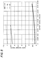
- Figure 5 shows the input voltage required at varying signal output levels. As can be seen, input voltage is a strong function of gas type and depends only weakly upon the gas flow rate.
- Figure 6 shows the output signal versus the volumetric flow rate.
- a reference fluid in this case air, according to Equation 14, wherein all gas properties are taken at 20°C. Any gas could have been selected as the reference fluid; similarly, any liquid is believed to be employable as a reference fluid where the test fluid is a liquid. It will be recognized that the small discrepancies between the response curves in Figure 7 can be eliminated by multiplying the normalized flow rate with an experimentally determined factor which was found to range between 0.8 to 1.1 for hydrogen, helium, carbon dioxide and argon.
- test gas is passed at a fixed, yet unknown, flow rate through the system depicted in Figure 3. It is desired to pass the test gas through the system at a flow rate of 500 sccm.
- the input voltage required to maintain the heating means 160°C above the ambient temperature is recorded as 6.3 volts.
- the output signal is also recorded.
- the input voltage and the output signal are provided as a data set to a processing means.
- the input voltage is compared with the reference input voltages generated in Example 1 and the identity of the test gas is determined to be helium.
- the flow function is solved for f, the flow rate, and found to be 400 sccm. Since this value is lower than 500 sccm, the fixed flow rate is increased. The flow rate is re-calculated and the fixed flow rate adjusted until the calculated flow rate is equal to 500 sccm.
- Example 2 The procedure of Example 2 is repeated, except that the processing means is a circuit such as depicted in Figure 9, having means for providing a voltage G ⁇ (92), means for signal addition (93 or 94), means for applying a logarithm function (95 or 96), and amplification means (97) having a gain of ⁇ ⁇ .
- the processing means is a circuit such as depicted in Figure 9, having means for providing a voltage G ⁇ (92), means for signal addition (93 or 94), means for applying a logarithm function (95 or 96), and amplification means (97) having a gain of ⁇ ⁇ .
- the input voltage and the output signal are provided as a data set to a processing means.
- the input voltage is compared with the reference input voltages generated in Example 1 and the identity of the test gas is determined to be helium.
- f is the fixed flow rate
- ⁇ ⁇ is the constant determined in Example 1 for helium
- G ⁇ is an experimentally derived constant voltage dependent upon the conduit
- v ⁇ is the output signal
- V ⁇ is the output signal at zero flow, 1.0 volts in the present case.
- the flow function is solved for f, the flow rate, and found to be 400 sccm. Since this value is lower than 500 sccm, the fixed flow rate is increased. The flow rate is re-calculated and the fixed flow rate adjusted until the calculated flow rate is equal to 500 sccm.
- test gas is passed through the system depicted in Figure 3 at a fixed, yet unknown, flow rate. It is desired to pass the test gas through the system at a flow rate of 500 sccm.
- the input voltage required to maintain the heating means 160°C above the ambient temperature is recorded as 6.6 volts.
- the output signal is recorded as 0.2 volts.
- the input voltage and output signal are provided to a processing means as a data set.
- the input voltage is compared with the reference input voltages generated in Example 1.
- the identity of the test gas cannot conclusively be determined by such a comparison, as its input voltage is between the reference input voltages for helium (6.3 volts) and hydrogen (6.9 volts). Therefore, the input voltage of the test gas at an output signal of 0.2 volts is compared with the input voltages for helium and hydrogen at an output signal of 0.2 volts, and the test gas is identified as helium. Air is selected as the reference fluid with which the test gas will be compared.
- the flow function is solved for f, the flow rate, and found to be 400 sccm. Since this value is lower than 500 sccm, the fixed flow rate is increased. The flow rate is re-calculated and the fixed flow rate adjusted until the calculated flow rate is equal to 500 sccm.
- f is the fixed flow rate
- ⁇ ⁇ and ⁇ ⁇ are the constants determined in Example 1 for helium
- ( ⁇ C ⁇ /k) ⁇ relates to air
- ( ⁇ C ⁇ /k) ⁇ relates to the test gas
- ⁇ is the density of the gas
- C ⁇ is the thermal capacity of the gas
- k the thermal conductivity of the gas
- G ⁇ is an experimentally derived constant voltage dependent upon the conduit
- v ⁇ is the output signal.
Landscapes
- General Physics & Mathematics (AREA)
- Physics & Mathematics (AREA)
- Fluid Mechanics (AREA)
- Chemical & Material Sciences (AREA)
- Health & Medical Sciences (AREA)
- Life Sciences & Earth Sciences (AREA)
- General Health & Medical Sciences (AREA)
- Analytical Chemistry (AREA)
- Chemical Kinetics & Catalysis (AREA)
- Electrochemistry (AREA)
- Immunology (AREA)
- Pathology (AREA)
- Biochemistry (AREA)
- Measuring Volume Flow (AREA)
Claims (8)
- Ein Verfahren des Bestimmens der Flußrate eines Testfluids in einem System, das folgende Merkmale aufweist:
eine Röhre (20) mit folgenden Merkmalen:
einem ersten Sensor (26a);
einem zweiten Sensor (28a) in einer ersten vorbestimmten Entfernung von dem ersten Sensor (26a);
einer Heizeinrichtung (24a) in einer zweiten vorbestimmten Entfernung sowohl von dem ersten Sensor (26a) als auch von dem zweiten Sensor (28a);
einer Ausgabeeinrichtung (34), die mit dem ersten Sensor (26a) und dem zweiten Sensor (28a) gekoppelt ist, die in der Lage ist, ein Testausgangssignal, das den Temperaturunterschied zwischen denselben darstellt, zu erzeugen; und
einer Verarbeitungseinrichtung;
wobei das Verfahren folgende Schritte aufweist:
Leiten des Testfluids durch die Röhre (20);
Anlegen einer Testeingangsspannung an die Heizeinrichtung (24a), um die Heizeinrichtung (24a) auf einer vorbestimmten Temperatur, die größer ist als die Temperatur der Röhre (20), zu halten;
Leiten der Testeingangsspannung und des Testausgangssignals zu der Verarbeitungseinrichtung (40);
Vergleichen der Testeingangsspannung mit zumindest einer Referenzeingangsspannung durch die Verarbeitungseinrichtung (40), um die Identität des Testfluids zu bestimmen;
Bestimmen der Flußrate des Testfluids mittels der Verarbeitungsrichtung (40) auf der Basis des Testausgangssignals und einer vorbestimmten Flußfunktion, die zu dem identifizierten Testfluid gehört. - Das Verfahren gemäß Anspruch 1, bei dem die Flußfunktion wie folgt lautet:

wobei ρ die Dichte des identifizierten Testfluids ist, Cp die thermische Kapazität des identifizierten Testfluids ist, L die zweite vorbestimmte Entfernung ist, k die thermische Leitfähigkeit des identifizierten Testfluids ist, Ψ eine Konstante ist, die von der Geometrie der Röhre (20) abhängt, und ΔT der Temperaturunterschied zwischen dem ersten Sensor (26a) und dem zweiten Sensor (28a) ist, um die Flußrate u des Testfluids zu bestimmen. - Das Verfahren gemaß Anspruch 1, bei dem die Flußfunktion wie folgt lautet:

wobei βtest eine experimentell hergeleitete Konstante abhängig von der Röhre (20) und dem identifizierten Testfluid ist, Gs eine experimentell hergeleitete konstante Spannung abhängig von der Röhre (20) ist und vο das Ausgangssignal ist, um die Flußrate, f, des Testfluids zu bestimmen. - Das Verfahren gemäß Anspruch 1, bei dem die Flußfunktion wie folgt lautet:

wobei βtest eine experimentell hergeleitete Konstante abhängig von der Röhre (20) und dem identifizierten Testfluid ist, Gs eine experimentell hergeleitete konstante Spannung abhängig von der Röhre (20) ist, vο das Ausgangssignal ist und voffset das Ausgangssignal bei einem Null-Fluß ist, um die Flußrate, f, des Testfluids zu bestimmen. - Das Verfahren gemaß Anspruch 1, bei dem die Flußfunktion wie folgt lautet:

wobei βtest eine experimentell hergeleitete Konstante abhängig von der Röhre (20) und dem identifizierten Testfluid ist, (ρCp/k)ref sich auf ein Referenzfluid bezieht, (ρCp/k)test sich auf das identifizierte Testfluid bezieht, ρ die Dichte des Fluids ist, Cp die thermische Kapazität des Fluids ist, k die thermische Leitfähigkeit des Fluids ist, Gs eine experimentell hergeleitete konstante Spannung abhängig von der Röhre (20) ist und vο das Testausgangssignal ist, um die Flußrate, f, des Testfluids zu bestimmen. - Das Verfahren gemäß Anspruch 1, bei dem die Flußfunktion wie folgt lautet:

wobei αtest und βtest experimentell hergeleitete Konstanten abhängig von der Röhre (20) und dem identifizierten Testfluid sind, (·Cp/k)ref sich auf ein Referenzfluid bezieht, (ρCp/k)test sich auf das identifizierte Testfluid bezieht, ρ die Dichte des Fluids ist, Cp die thermische Kapazität des Fluids ist, k die thermische Leitfähigkeit des Fluids ist, Gs eine experimentell hergeleitete konstante Spannung abhängig von der Röhre (20) ist und vο das Testausgangssignal ist, um die Flußrate, f, des identifizierten Testfluids zu bestimmen. - Das Verfahren gemäß Anspruch 1, bei dem das Testfluid ein Gas ist.
- Ein System zum Bestimmen der Flußrate eines Fluids, das folgende Merkmale aufweist:
eine Röhre (20) mit folgenden Merkmalen:
einem ersten Sensor (26a);
einem zweiten Sensor (28a) in einer vorbestimmten Entfernung von dem ersten Sensor (26a); und
einer Heizeinrichtung (24a) zwischen dem ersten Sensor (26a) und dem zweiten Sensor (28a);
eine Ausgangseinrichtung (34), die mit dem ersten Sensor (26a) und dem zweiten Sensor (28a) gekoppelt ist, die in der Lage ist, ein Testausgangssignal zu erzeugen, das den Temperaturunterschied zwischen dem ersten Sensor (26a) und dem zweiten Sensor (28a) darstellt;
eine Spannungsquelle (32), die mit der Heizeinrichtung (24a) gekoppelt ist, die in der Lage ist, eine Testeingangsspannung an dieselbe anzulegen;
eine Einrichtung (12) zum Leiten des Fluids durch die Röhre (20); und
eine Verarbeitungseinrichtung (40);
dadurch gekennzeichnet, daß
die Spannungsquelle (32) die Heizeinrichtung (24a) auf einer vorbestimmten Temperatur hält, die größer ist als die Temperatur der Röhre (20);
die Verarbeitungseinrichtung (40), die Testeingangsspannung und das Testausgangssignal empfängt; die Testeingangsspannung mit zumindest einer Referenzeingangsspannung vergleicht, um die Identität des Testfluids zu bestimmen; und die Flußrate des Testfluids auf der Basis des Testausgangssignals und einer vorbestimmten Flußfunktion, die zu dem identifizierten Testfluid gehört, bestimmt.
Applications Claiming Priority (2)
| Application Number | Priority Date | Filing Date | Title |
|---|---|---|---|
| US61142590A | 1990-11-09 | 1990-11-09 | |
| US611425 | 1990-11-09 |
Publications (2)
| Publication Number | Publication Date |
|---|---|
| EP0484645A1 EP0484645A1 (de) | 1992-05-13 |
| EP0484645B1 true EP0484645B1 (de) | 1995-04-26 |
Family
ID=24448966
Family Applications (1)
| Application Number | Title | Priority Date | Filing Date |
|---|---|---|---|
| EP91114677A Expired - Lifetime EP0484645B1 (de) | 1990-11-09 | 1991-08-30 | Verfahren und Systeme zur Identifizierung von Flüssigkeiten und Bestimmung der Strömung |
Country Status (4)
| Country | Link |
|---|---|
| US (1) | US5515295A (de) |
| EP (1) | EP0484645B1 (de) |
| JP (2) | JPH04268415A (de) |
| DE (1) | DE69109236T2 (de) |
Families Citing this family (44)
| Publication number | Priority date | Publication date | Assignee | Title |
|---|---|---|---|---|
| US5524084A (en) * | 1994-12-30 | 1996-06-04 | Hewlett-Packard Company | Method and apparatus for improved flow and pressure measurement and control |
| JP3114139B2 (ja) * | 1995-01-24 | 2000-12-04 | 株式会社山武 | 熱伝導率計 |
| US5706214A (en) * | 1995-03-29 | 1998-01-06 | Eaton Corporation | Calibration of microcomputer-based metering apparatus |
| EP0784200A3 (de) * | 1996-01-12 | 1998-02-11 | Landis & Gyr Technology Innovation AG | Anordnung zur Durchflussmessung eines gasförmigen Stoffes |
| CA2617287C (en) * | 1997-06-17 | 2011-11-15 | Fisher & Paykel Healthcare Limited | Respiratory humidification system |
| GB9823560D0 (en) * | 1998-10-28 | 1998-12-23 | Brulines Limited | System and method for monitoring fluid flow |
| GB9823559D0 (en) * | 1998-10-28 | 1998-12-23 | Brulines Limited | Device and method for identification of a fluid in a conduit |
| US6447520B1 (en) * | 2001-03-19 | 2002-09-10 | Advanced Medical Optics, Inc. | IOL insertion apparatus with IOL engagement structure and method for using same |
| JP4050857B2 (ja) * | 1999-04-27 | 2008-02-20 | 矢崎総業株式会社 | 流体判別装置及び流量計測装置 |
| AU6719100A (en) * | 1999-09-09 | 2001-04-10 | Sensirion Ag | Method and device for precision mass flow measurement |
| US7387123B2 (en) * | 2001-11-30 | 2008-06-17 | Viasys Manufacturing, Inc. | Gas identification system and volumetrically correct gas delivery system |
| US6932796B2 (en) * | 2002-05-15 | 2005-08-23 | Tearafuse, Inc. | Liquid metering system |
| US6796172B2 (en) * | 2002-07-31 | 2004-09-28 | Hewlett-Packard Development Company, L.P. | Flow sensor |
| US6871535B2 (en) | 2002-08-14 | 2005-03-29 | Hewlett-Packard Development Company, L.P. | Flow direction detector |
| EP1426740B1 (de) * | 2002-11-27 | 2014-11-19 | Sensirion Holding AG | Vorrichtung zur Messung des Flusses und mindestens eines Materialparameters eines Fluids |
| US6955602B2 (en) * | 2003-05-15 | 2005-10-18 | Zi Technology Corporation Ltd | Text entry within a video game |
| US6868723B2 (en) * | 2003-05-16 | 2005-03-22 | Mks Instruments, Inc. | Thermal anemometry mass flow measurement apparatus and method |
| US7481213B2 (en) * | 2004-02-11 | 2009-01-27 | Hewlett-Packard Development Company, L.P. | Medicament dispenser |
| US7467630B2 (en) * | 2004-02-11 | 2008-12-23 | Hewlett-Packard Development Company, L.P. | Medicament dispenser |
| US7107835B2 (en) * | 2004-09-08 | 2006-09-19 | Honeywell International Inc. | Thermal mass flow sensor |
| US7644632B2 (en) * | 2005-01-15 | 2010-01-12 | Best John W | Viscometric flowmeter |
| US20060159091A1 (en) * | 2005-01-19 | 2006-07-20 | Arjen Boers | Active multicast information protocol |
| US8752548B2 (en) * | 2007-06-28 | 2014-06-17 | Maquet Critical Care Ab | Patient ventilation system with a gas identification unit |
| EP2015056B1 (de) * | 2007-07-07 | 2010-04-07 | Mems Ag | Verfahren und Sensor zur Bestimmung einer brenntechnisch relevanten Größe eines Gasgemisches |
| EP2037234A1 (de) * | 2007-09-14 | 2009-03-18 | General Electric Company | Flüssigkeitsdetektor |
| EP2175246B1 (de) | 2008-10-09 | 2017-07-19 | Sensirion AG | Verfahren zur Messung eines Parameters einer Fluidzusammensetzung mithilfe eines Flusssensors |
| FR2940434B1 (fr) * | 2008-12-19 | 2011-01-21 | Commissariat Energie Atomique | Dispositif de regulation d'un anemometre a fil |
| FR2940453B1 (fr) | 2008-12-19 | 2011-03-25 | Commissariat Energie Atomique | Sonde anemometrique a fils en "x" et son procede de realisation |
| EP2204555B1 (de) * | 2009-01-02 | 2011-08-03 | Sensirion AG | Ammoniakspeichersystem |
| US8943887B2 (en) * | 2009-12-18 | 2015-02-03 | Waters Technologies Corporation | Thermal-based flow sensing apparatuses and methods for high-performance liquid chromatography |
| CN101762718B (zh) * | 2010-01-29 | 2012-02-01 | 北京信息科技大学 | 测量风速的方法和装置 |
| EP2392898B1 (de) | 2010-06-04 | 2017-12-13 | Sensirion AG | Sensorensystem |
| SE537180C2 (sv) * | 2010-11-12 | 2015-02-24 | St Jude Medical Systems Ab | Extrakorporeal gränssnittsenhet för ett intravaskulärt mätningssystem |
| SI24577A (sl) * | 2013-12-13 | 2015-06-30 | Univerza v Ljubljani, Fakulteta za strojništvo - LMPS | Termiäťni merilnik masnega toka in metoda identifikacije vrste plina |
| EP3029429B1 (de) * | 2014-12-04 | 2020-10-07 | Sensirion AG | Bestimmung einer Flüssigkeitszusammensetzung in einer Massenströmungssteuerung |
| GB2553681B (en) | 2015-01-07 | 2019-06-26 | Homeserve Plc | Flow detection device |
| GB201501935D0 (en) | 2015-02-05 | 2015-03-25 | Tooms Moore Consulting Ltd And Trow Consulting Ltd | Water flow analysis |
| JP6417999B2 (ja) * | 2015-02-19 | 2018-11-07 | 東京エレクトロン株式会社 | 処理液供給装置、処理液供給方法及び記憶媒体 |
| EP3421947B1 (de) | 2017-06-30 | 2019-08-07 | Sensirion AG | Betriebsverfahren für eine durchflusssensorvorrichtung |
| DE102017128953B4 (de) | 2017-12-06 | 2021-12-23 | Vereta Gmbh | Messeinheit zur Erfassung dynamischer Parameter und bzw. oder physikalischer Eigenschaften von strömenden Medien, vorzugsweise von strömenden Fluiden |
| CN109736792B (zh) * | 2019-01-07 | 2022-09-06 | 中国石油集团川庆钻探工程有限公司 | 天然气储层及其含流体性质自动识别方法 |
| CN111426777B (zh) * | 2020-06-12 | 2020-11-27 | 赛默飞世尔(上海)仪器有限公司 | 确定管路体积的方法、液相色谱系统及管路体积确定装置 |
| JP7698589B2 (ja) * | 2022-01-12 | 2025-06-25 | 株式会社東芝 | センサ |
| CN118981980A (zh) * | 2024-08-02 | 2024-11-19 | 上海勘测设计研究院有限公司 | 一种基于流线原理的辅助河道整治方法、装置及设备 |
Citations (2)
| Publication number | Priority date | Publication date | Assignee | Title |
|---|---|---|---|---|
| EP0387025A1 (de) * | 1989-03-10 | 1990-09-12 | Yamatake-Honeywell Co. Ltd. | Temperaturkompensationsschaltung |
| WO1991019170A1 (en) * | 1990-06-04 | 1991-12-12 | Mcpherson's Limited | Flow sensor and control system |
Family Cites Families (16)
| Publication number | Priority date | Publication date | Assignee | Title |
|---|---|---|---|---|
| US4070908A (en) * | 1976-09-28 | 1978-01-31 | The Boeing Company | Anemometer compensator linearizer |
| US4122722A (en) * | 1976-09-28 | 1978-10-31 | The Boeing Company | Anemometer compensator linearizer |
| NO148689C (no) * | 1976-12-20 | 1983-11-30 | Bronson M Potter | Detektorapparat for aa detektere naervaer av en ikke-blandbar fremmedvaeske paa overflaten av en annen vaeske |
| US4375667A (en) * | 1980-08-14 | 1983-03-01 | Buchan Roy M | Personal air sampling system |
| IT1139480B (it) * | 1981-09-23 | 1986-09-24 | Cazzaniga Spa | Metodo e apparecchiature per la misurazione diretta di energia termica trasferita a mezzo di un fluido |
| JPS58118914A (ja) * | 1982-01-11 | 1983-07-15 | Nippon Soken Inc | 流体流量測定方法および装置 |
| JPS58223021A (ja) * | 1982-06-21 | 1983-12-24 | Oval Eng Co Ltd | 器差調整回路 |
| JPS59153159A (ja) * | 1983-02-21 | 1984-09-01 | Hitachi Ltd | ガス検出装置 |
| US4581714A (en) * | 1983-09-09 | 1986-04-08 | Sensormedics Corporation | Method of calibrating and linearizing the output of fluid measuring instruments |
| US4812747A (en) * | 1985-10-03 | 1989-03-14 | Eaton Corporation | Transducer linearizing system |
| US4884215A (en) * | 1987-02-27 | 1989-11-28 | Jabil Circuit Company | Airflow sensor and control circuit |
| US4847783A (en) * | 1987-05-27 | 1989-07-11 | Richard Grace | Gas sensing instrument |
| US4944035A (en) * | 1988-06-24 | 1990-07-24 | Honeywell Inc. | Measurement of thermal conductivity and specific heat |
| US4885938A (en) * | 1988-12-16 | 1989-12-12 | Honeywell Inc. | Flowmeter fluid composition correction |
| NL8900474A (nl) * | 1989-02-24 | 1990-09-17 | Bronkhorst High Tech Bv | Massa-debietmeter met temperatuursensoren. |
| US5177696A (en) * | 1989-12-28 | 1993-01-05 | Honeywell Inc. | Method of determination of gas properties at reference conditions |
-
1991
- 1991-08-30 DE DE69109236T patent/DE69109236T2/de not_active Expired - Fee Related
- 1991-08-30 EP EP91114677A patent/EP0484645B1/de not_active Expired - Lifetime
- 1991-11-08 JP JP3293171A patent/JPH04268415A/ja active Pending
-
1994
- 1994-12-22 US US08/361,915 patent/US5515295A/en not_active Expired - Fee Related
-
2001
- 2001-05-21 JP JP2001003153U patent/JP2607815Y2/ja not_active Expired - Fee Related
Patent Citations (2)
| Publication number | Priority date | Publication date | Assignee | Title |
|---|---|---|---|---|
| EP0387025A1 (de) * | 1989-03-10 | 1990-09-12 | Yamatake-Honeywell Co. Ltd. | Temperaturkompensationsschaltung |
| WO1991019170A1 (en) * | 1990-06-04 | 1991-12-12 | Mcpherson's Limited | Flow sensor and control system |
Also Published As
| Publication number | Publication date |
|---|---|
| JP2607815Y2 (ja) | 2003-03-31 |
| EP0484645A1 (de) | 1992-05-13 |
| JP2001000036U (ja) | 2001-10-19 |
| JPH04268415A (ja) | 1992-09-24 |
| DE69109236T2 (de) | 1996-01-11 |
| DE69109236D1 (de) | 1995-06-01 |
| US5515295A (en) | 1996-05-07 |
Similar Documents
| Publication | Publication Date | Title |
|---|---|---|
| EP0484645B1 (de) | Verfahren und Systeme zur Identifizierung von Flüssigkeiten und Bestimmung der Strömung | |
| US7720617B2 (en) | Flow sensor signal conversion | |
| US5642278A (en) | Method and apparatus for temperature and pressure compensation of pneumatic manifolds | |
| US5524084A (en) | Method and apparatus for improved flow and pressure measurement and control | |
| Kayser et al. | Discharge coefficients for compressible flow through small-diameter orifices and convergent nozzles | |
| US5033284A (en) | Calibration method for gas or vapor relative concentration sensor | |
| US20110191038A1 (en) | Mass flow controller with improved dynamic response | |
| Hinkle et al. | Toward understanding the fundamental mechanisms and properties of the thermal mass flow controller | |
| US5494826A (en) | Microcalorimeter sensor for the measurement of heat content of natural gas | |
| US5012432A (en) | Microcalorimeter sensor for the measurement of heat content of natural gas | |
| US5303167A (en) | Absolute pressure sensor and method | |
| US20050044950A1 (en) | AC type flowmeter and method of mapping flow rate data for the same | |
| US5915269A (en) | Method and apparatus to compensate for gas chromatograph column permeability | |
| Bruun et al. | The calibration of inclined hot-wire probes | |
| EP3546921B1 (de) | Probenidentifikationsverfahren basierend auf chemischer sensormessung | |
| US20020077759A1 (en) | Microflow based differential pressure sensor | |
| CN117043555A (zh) | 热式传感器和用于操作热式传感器的方法 | |
| Mielle | Managing dynamic thermal exchanges in commercial semiconduting gas sensors | |
| US6112576A (en) | Gas analyzer with background gas compensation | |
| Han et al. | Study on the transient characteristics of the sensor tube of a thermal mass flow meter | |
| US6962077B2 (en) | System and method of measuring convection induced impedance gradients to determine liquid flow rates | |
| EP4517277A1 (de) | Flüssigkeitsdurchflussmessgerät und zugehöriges verfahren | |
| GB2069726A (en) | Fluid flow control apparatus and method | |
| Cai et al. | Identification of odors using a sensor array with kinetic working temperature and Fourier spectrum analysis | |
| Durst et al. | Mass flow-rate control unit to calibrate hot-wire sensors |
Legal Events
| Date | Code | Title | Description |
|---|---|---|---|
| PUAI | Public reference made under article 153(3) epc to a published international application that has entered the european phase |
Free format text: ORIGINAL CODE: 0009012 |
|
| AK | Designated contracting states |
Kind code of ref document: A1 Designated state(s): DE FR GB |
|
| 17P | Request for examination filed |
Effective date: 19920713 |
|
| 17Q | First examination report despatched |
Effective date: 19940329 |
|
| GRAA | (expected) grant |
Free format text: ORIGINAL CODE: 0009210 |
|
| AK | Designated contracting states |
Kind code of ref document: B1 Designated state(s): DE FR GB |
|
| REF | Corresponds to: |
Ref document number: 69109236 Country of ref document: DE Date of ref document: 19950601 |
|
| ET | Fr: translation filed | ||
| PLBE | No opposition filed within time limit |
Free format text: ORIGINAL CODE: 0009261 |
|
| STAA | Information on the status of an ep patent application or granted ep patent |
Free format text: STATUS: NO OPPOSITION FILED WITHIN TIME LIMIT |
|
| 26N | No opposition filed | ||
| PGFP | Annual fee paid to national office [announced via postgrant information from national office to epo] |
Ref country code: FR Payment date: 19990802 Year of fee payment: 9 |
|
| REG | Reference to a national code |
Ref country code: GB Ref legal event code: 732E |
|
| REG | Reference to a national code |
Ref country code: GB Ref legal event code: 732E |
|
| PG25 | Lapsed in a contracting state [announced via postgrant information from national office to epo] |
Ref country code: FR Free format text: LAPSE BECAUSE OF NON-PAYMENT OF DUE FEES Effective date: 20010430 |
|
| REG | Reference to a national code |
Ref country code: FR Ref legal event code: ST |
|
| REG | Reference to a national code |
Ref country code: GB Ref legal event code: IF02 |
|
| PGFP | Annual fee paid to national office [announced via postgrant information from national office to epo] |
Ref country code: GB Payment date: 20020821 Year of fee payment: 12 |
|
| PGFP | Annual fee paid to national office [announced via postgrant information from national office to epo] |
Ref country code: DE Payment date: 20020830 Year of fee payment: 12 |
|
| PG25 | Lapsed in a contracting state [announced via postgrant information from national office to epo] |
Ref country code: GB Free format text: LAPSE BECAUSE OF NON-PAYMENT OF DUE FEES Effective date: 20030830 |
|
| PG25 | Lapsed in a contracting state [announced via postgrant information from national office to epo] |
Ref country code: DE Free format text: LAPSE BECAUSE OF NON-PAYMENT OF DUE FEES Effective date: 20040302 |
|
| GBPC | Gb: european patent ceased through non-payment of renewal fee |