EP0484695A1 - Dispositif et procédé pour fabriquer des moules carapaces - Google Patents
Dispositif et procédé pour fabriquer des moules carapaces Download PDFInfo
- Publication number
- EP0484695A1 EP0484695A1 EP91117434A EP91117434A EP0484695A1 EP 0484695 A1 EP0484695 A1 EP 0484695A1 EP 91117434 A EP91117434 A EP 91117434A EP 91117434 A EP91117434 A EP 91117434A EP 0484695 A1 EP0484695 A1 EP 0484695A1
- Authority
- EP
- European Patent Office
- Prior art keywords
- sand
- hot air
- hood
- model plate
- resin
- Prior art date
- Legal status (The legal status is an assumption and is not a legal conclusion. Google has not performed a legal analysis and makes no representation as to the accuracy of the status listed.)
- Withdrawn
Links
- 238000000034 method Methods 0.000 title claims abstract description 10
- 238000010112 shell-mould casting Methods 0.000 title 1
- 239000004576 sand Substances 0.000 claims abstract description 35
- 239000011347 resin Substances 0.000 claims abstract description 22
- 229920005989 resin Polymers 0.000 claims abstract description 22
- 239000000203 mixture Substances 0.000 claims abstract description 11
- 238000002844 melting Methods 0.000 claims abstract description 5
- 230000008018 melting Effects 0.000 claims abstract description 5
- 238000004519 manufacturing process Methods 0.000 claims description 4
- 238000010438 heat treatment Methods 0.000 description 10
- 230000002093 peripheral effect Effects 0.000 description 2
- 239000000463 material Substances 0.000 description 1
- 239000000155 melt Substances 0.000 description 1
- 238000000465 moulding Methods 0.000 description 1
- 238000011417 postcuring Methods 0.000 description 1
- 230000005855 radiation Effects 0.000 description 1
- 229920003987 resole Polymers 0.000 description 1
Images
Classifications
-
- B—PERFORMING OPERATIONS; TRANSPORTING
- B22—CASTING; POWDER METALLURGY
- B22C—FOUNDRY MOULDING
- B22C13/00—Moulding machines for making moulds or cores of particular shapes
- B22C13/08—Moulding machines for making moulds or cores of particular shapes for shell moulds or shell cores
-
- B—PERFORMING OPERATIONS; TRANSPORTING
- B22—CASTING; POWDER METALLURGY
- B22C—FOUNDRY MOULDING
- B22C9/00—Moulds or cores; Moulding processes
- B22C9/12—Treating moulds or cores, e.g. drying, hardening
- B22C9/123—Gas-hardening
Definitions
- the invention relates to a process for the production of mold masks, in which a sand-resin mixture is applied to a hot model plate, a sand mask of the desired thickness is formed by melting the resin and excess sand is removed, and a device for the production of mold masks with a hot model plate.
- a pourable and dry sand-resin mixture is applied to a hot model plate.
- the resin melts and changes from its resol state (A state) to the resitol state (B state).
- the heating of the sand progresses outwards from the model plate.
- the mask is then post-hardened, whereby the resin changes into the hard, infusible, resit state (C state) and can then be lifted off the model plate.
- the post-curing takes place by applying heat to the side of the sand mask facing away from the model plate by means of gas heating, heat radiation, gas or electric radiators, such as heating spirals or the like, arranged above the sand mask, which radiate their heat onto the sand mask.
- gas heating, heat radiation, gas or electric radiators such as heating spirals or the like
- This caused quite uneven heating of different areas of the sand mask, depending on whether the areas were located closer or further away from the heater.
- Surfaces arranged with a greater inclination to the heating plane were also poorly heated, since the heat radiated in per unit area is less than regions of the sand mask arranged parallel to the heating plane.
- the object of the invention is to achieve uniform application of heat to the sand mask and thus uniform curing while avoiding the aforementioned disadvantages.
- the stated object is achieved in a method of the generic type in that hot air is blown onto the sand mask formed in order to cure the resin.
- a generic device solves the problem with a hot air device.
- the sand mask is not irradiated with heat, but rather the heat is transmitted through the air supplied to the sand mask, that is to say by convection and preferably forced convection, uniform heating of the Sand mask can be achieved regardless of levels of individual mask areas or alignment thereof relative to a reference plane.
- a further development of the method provides that a largely closed space is formed above the sand mask before hot air is inflated.
- the device according to the invention is designed in such a way that the hot air device is or can be connected via a line to a hood which can be brought over the model plate. If the hood is to be placed as close as possible to the model plate for heating, then it must be removable from it for the application of the sand-resin mixture.
- the line can either be a flexible hose, such as a corrugated hose, or another type, provided that the hose is made of material that is resistant to between 220 and 400 degrees, depending on the resin, at the required temperature.
- connection between the hot air device and the hood has separable insulated pipes which form a continuous connection for the hot air when the hood is lowered onto the mold plate, a further development being distinguished in particular by the end faces of pipe parts being inclined to the vertical their axis are designed so that they can be moved along to each other up to a tight connection of the pipe parts.
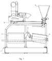
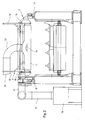
- the device according to the invention has, in a manner known per se, a frame 1 which carries a carrier 2 for a model plate 3 (FIG. 2) and a sand hood 4.
- Carrier 2 and sand hood 4 are both six-jointed, so that they can be closed by applying a sand-resin mixture to the model plate 3 and pouring the excess sand back into the hood 4 by pivoting about the axis 6.
- the carrier 2 has an underheater for heating the model plate 3.
- a hopper 7 is further arranged, which is in the open position of the hood 4 above the opening thereof, so that the sand-resin mixture can be filled from the funnel 7 into the open hood 4.
- a heating hood 11 On the frame 1 there are also - approximately at the level of the funnel 7 - parallel rails 8 on which carriages 9 for a heating hood 11 can be moved horizontally.
- the carriages 9 have rollers 15 along which the hood 11 can be lowered and raised by means of vertically directed rails 12 connected to it.
- a supply air nozzle 13 On the top of the hood 11, a supply air nozzle 13 is attached. Below the mouth 14 of the air inlet 13 there is a chicane 14, through which the hot air supplied through the nozzle 13 is distributed over the entire surface of the hood 11.
- a hot air device 16 is provided to the side of the frame 1, which has an outlet pipe 17 which is guided next to the travel space of the hood 11 and there has a transfer opening 18 which interacts with a receiving opening 19 of the feed connector 13 when the hood 11 is on the model plate 3 is lowered.
- the end faces of the transfer opening 18 and the receiving opening 19 are aligned obliquely in the same way, the upper region of the transfer opening 18 being set back further, that is to say shortened further than the lower region of the opening.
- the sand-resin mixture is applied to the heated model plate 3 in a known manner.
- sand is filled into the hood 4 from the funnel 7.
- Carrier 2 for the model plate 3 and hood 4 are closed by pivoting about the axis 6.
- the sand-resin mixture is applied to the model plate 3 by pivoting further.
- the resin softens and binds a certain layer of sand on the model plate 3. Excess sand and resin remain in the latter when the carrier 2 and hood 4 are subsequently opened.
- the hot air hood 11 is then lowered onto the model plate 3 and thus over the resin-sand layer or sand shell located thereon, by lowering the rails 12 connected to the hood 11 along rollers 15 until the openings 18, 19 are aligned with one another and the Establish the continuous hot air path mentioned.
- the hot air device 16 is put into operation and hot air 16 is in via the pipes 17, 18, 19, 13 in the hood 11 blown. When entering, it is distributed by chicane 14 over the entire hood space, so that it hits the sand bowl on the model plate 3 evenly. This results in a very uniform melting and hardening of the resin in its hard, infusible resit state (C state).
- the hood 11 is raised again and then the sand shell or mask can be lifted off the model plate 3 and assembled as a mold mask part with other mold mask parts for complete molding in order to cast the desired part to be produced.
Landscapes
- Engineering & Computer Science (AREA)
- Mechanical Engineering (AREA)
- Casting Devices For Molds (AREA)
Applications Claiming Priority (2)
| Application Number | Priority Date | Filing Date | Title |
|---|---|---|---|
| DE4033888 | 1990-10-25 | ||
| DE19904033888 DE4033888A1 (de) | 1990-10-25 | 1990-10-25 | Verfahren und vorrichtung zur sandmaskenherstellung |
Publications (1)
| Publication Number | Publication Date |
|---|---|
| EP0484695A1 true EP0484695A1 (fr) | 1992-05-13 |
Family
ID=6416995
Family Applications (1)
| Application Number | Title | Priority Date | Filing Date |
|---|---|---|---|
| EP91117434A Withdrawn EP0484695A1 (fr) | 1990-10-25 | 1991-10-12 | Dispositif et procédé pour fabriquer des moules carapaces |
Country Status (3)
| Country | Link |
|---|---|
| EP (1) | EP0484695A1 (fr) |
| JP (1) | JPH04262833A (fr) |
| DE (1) | DE4033888A1 (fr) |
Citations (5)
| Publication number | Priority date | Publication date | Assignee | Title |
|---|---|---|---|---|
| FR1059189A (fr) * | 1952-06-24 | 1954-03-23 | Tech Modernes De Fonderie | Machine pour la confection de moules de fonderie à l'aide de noyaux extérieurs |
| GB745288A (en) * | 1952-12-02 | 1956-02-22 | Alfred Bartlett Smith | Improvements relating to the manufacture of shell moulds |
| GB799861A (en) * | 1954-11-09 | 1958-08-13 | Clifford Ross Smith | Improvements relating to stoves for drying foundry moulds and cores |
| CH654501A5 (en) * | 1981-11-19 | 1986-02-28 | Sintokogio Ltd | Process for mould production |
| JPS62176634A (ja) * | 1986-01-28 | 1987-08-03 | Sintokogio Ltd | シエル中子の造型方法 |
Family Cites Families (4)
| Publication number | Priority date | Publication date | Assignee | Title |
|---|---|---|---|---|
| FR1002161A (fr) * | 1946-08-06 | 1952-03-03 | Procédé de confection de noyaux creux et de carapaces de moules de fonderie ou de pièces moulées de toute nature | |
| DE1247560B (de) * | 1962-05-17 | 1967-08-17 | Nat Acme Co | Maschine zum Herstellen von Schalenkernen |
| US3850224A (en) * | 1973-07-30 | 1974-11-26 | Sherwood Refractories | Process and apparatus for drying shell molds |
| US4114285A (en) * | 1976-08-09 | 1978-09-19 | United Technologies Corporation | Method and apparatus for drying investment casting molds |
-
1990
- 1990-10-25 DE DE19904033888 patent/DE4033888A1/de not_active Withdrawn
-
1991
- 1991-10-12 EP EP91117434A patent/EP0484695A1/fr not_active Withdrawn
- 1991-10-24 JP JP27590891A patent/JPH04262833A/ja active Pending
Patent Citations (5)
| Publication number | Priority date | Publication date | Assignee | Title |
|---|---|---|---|---|
| FR1059189A (fr) * | 1952-06-24 | 1954-03-23 | Tech Modernes De Fonderie | Machine pour la confection de moules de fonderie à l'aide de noyaux extérieurs |
| GB745288A (en) * | 1952-12-02 | 1956-02-22 | Alfred Bartlett Smith | Improvements relating to the manufacture of shell moulds |
| GB799861A (en) * | 1954-11-09 | 1958-08-13 | Clifford Ross Smith | Improvements relating to stoves for drying foundry moulds and cores |
| CH654501A5 (en) * | 1981-11-19 | 1986-02-28 | Sintokogio Ltd | Process for mould production |
| JPS62176634A (ja) * | 1986-01-28 | 1987-08-03 | Sintokogio Ltd | シエル中子の造型方法 |
Non-Patent Citations (1)
| Title |
|---|
| PATENT ABSTRACTS OF JAPAN, Band 12, Nr. 18 (M-660)[2865], 20. Januar 1988; & JP-A-62 176 634 (SINTOKOGIO LTD) 03-08-1987 * |
Also Published As
| Publication number | Publication date |
|---|---|
| JPH04262833A (ja) | 1992-09-18 |
| DE4033888A1 (de) | 1992-04-30 |
Similar Documents
| Publication | Publication Date | Title |
|---|---|---|
| DE4440397C2 (de) | Verfahren zum Herstellen von Gußformen | |
| DE69311843T2 (de) | Verfahren und Vorrichtung zum Biegen und Härten von Glasscheiben | |
| DE2121424C3 (fr) | ||
| DE3809825A1 (de) | Verfahren und vorrichtung zum herstellen von kunststoff-formfolien | |
| DE3304073A1 (de) | Verfahren zur erstellung von formen fuer das spritzgiessen, insbesondere von werkzeugen fuer das spritzgiessen von kunststoff | |
| DE19960220A1 (de) | Verfahren zur Herstellung von Formteilen sowie einer Vorrichtung zur Durchführung dieses Verfahrens | |
| DE1265350C2 (de) | Blasmaschinen zum Herstellen von Giessereiformen und -kernen | |
| DE1201156B (de) | Giessform fuer die aluminothermische Schienen-schweissung | |
| DE3831400A1 (de) | Verfahren zum giessen eines metallgegenstandes | |
| DE2430408A1 (de) | Verfahren und vorrichtung zum herstellen einer form | |
| DE4033888A1 (de) | Verfahren und vorrichtung zur sandmaskenherstellung | |
| DE2914281A1 (de) | Verfahren und vorrichtung zum herstellen von schokoladeformteilen | |
| WO2006027174A1 (fr) | Procede et dispositif de coulee de metal en fusion | |
| DE1558139B1 (de) | Verfahren zum Halten von Kernen in Praezisionsgiessformen | |
| DE2834721A1 (de) | Kernformmaschine fuer das no-bake- verfahren | |
| DE969774C (de) | Verfahren zur Herstellung von Giessformen | |
| EP0143954B1 (fr) | Procédé de fabrication de parties de moule, selon le procédé en boîte froide et appareil de moulage utilisé | |
| DE2134389A1 (de) | Verfahren zum Herstellen von Form teilen aus Polyimidharzen | |
| EP0567065B1 (fr) | Appareil pour coller des parties de modèle | |
| EP0334074A2 (fr) | Procédé et appareil de fabrication de feuilles formées en matière plastique | |
| DE2317151A1 (de) | Metallgiessverfahren und vorrichtung zur durchfuehrung des verfahrens | |
| DE4125750A1 (de) | Herstellungsverfahren von kunststoffwannen | |
| EP1655121B1 (fr) | Procédé et dispositif pour le formage de feuilles de plastique. | |
| DE10039877A1 (de) | Verfahren und Gießform zur Herstellung von Gussstücken | |
| DE2623303B2 (de) | Einrichtung zum Herstellen von Formkernen aus Salzschmelzen |
Legal Events
| Date | Code | Title | Description |
|---|---|---|---|
| PUAI | Public reference made under article 153(3) epc to a published international application that has entered the european phase |
Free format text: ORIGINAL CODE: 0009012 |
|
| AK | Designated contracting states |
Kind code of ref document: A1 Designated state(s): CH DE ES FR GB IT LI SE |
|
| STAA | Information on the status of an ep patent application or granted ep patent |
Free format text: STATUS: THE APPLICATION HAS BEEN WITHDRAWN |
|
| 18W | Application withdrawn |
Withdrawal date: 19920603 |