EP0484701A1 - Dispositif capable de se déplacer dans un tuyau; procédé de déplacement dans un tuyau et dispositif de support - Google Patents
Dispositif capable de se déplacer dans un tuyau; procédé de déplacement dans un tuyau et dispositif de support Download PDFInfo
- Publication number
- EP0484701A1 EP0484701A1 EP91117578A EP91117578A EP0484701A1 EP 0484701 A1 EP0484701 A1 EP 0484701A1 EP 91117578 A EP91117578 A EP 91117578A EP 91117578 A EP91117578 A EP 91117578A EP 0484701 A1 EP0484701 A1 EP 0484701A1
- Authority
- EP
- European Patent Office
- Prior art keywords
- tube
- moving
- arms
- support
- members
- Prior art date
- Legal status (The legal status is an assumption and is not a legal conclusion. Google has not performed a legal analysis and makes no representation as to the accuracy of the status listed.)
- Withdrawn
Links
- 238000000034 method Methods 0.000 title claims abstract description 9
- 230000007246 mechanism Effects 0.000 title claims description 33
- 230000008602 contraction Effects 0.000 claims description 21
- 238000007689 inspection Methods 0.000 claims description 6
- 230000001360 synchronised effect Effects 0.000 claims description 3
- 241000219098 Parthenocissus Species 0.000 abstract description 32
- XLYOFNOQVPJJNP-UHFFFAOYSA-N water Substances O XLYOFNOQVPJJNP-UHFFFAOYSA-N 0.000 description 8
- 238000004140 cleaning Methods 0.000 description 7
- 230000008878 coupling Effects 0.000 description 5
- 238000010168 coupling process Methods 0.000 description 5
- 238000005859 coupling reaction Methods 0.000 description 5
- 238000012423 maintenance Methods 0.000 description 4
- 230000008859 change Effects 0.000 description 3
- 238000006243 chemical reaction Methods 0.000 description 3
- 229910000831 Steel Inorganic materials 0.000 description 2
- 230000009471 action Effects 0.000 description 2
- 238000011109 contamination Methods 0.000 description 2
- 229910052571 earthenware Inorganic materials 0.000 description 2
- 230000000694 effects Effects 0.000 description 2
- 229920001971 elastomer Polymers 0.000 description 2
- 231100001261 hazardous Toxicity 0.000 description 2
- 239000013049 sediment Substances 0.000 description 2
- 239000010959 steel Substances 0.000 description 2
- 230000006978 adaptation Effects 0.000 description 1
- 230000037396 body weight Effects 0.000 description 1
- 238000011161 development Methods 0.000 description 1
- 239000000806 elastomer Substances 0.000 description 1
- 230000002349 favourable effect Effects 0.000 description 1
- 239000000835 fiber Substances 0.000 description 1
- 239000000463 material Substances 0.000 description 1
- 238000012986 modification Methods 0.000 description 1
- 230000004048 modification Effects 0.000 description 1
- 238000010422 painting Methods 0.000 description 1
- 230000000717 retained effect Effects 0.000 description 1
- 238000012360 testing method Methods 0.000 description 1
Images


Classifications
-
- F—MECHANICAL ENGINEERING; LIGHTING; HEATING; WEAPONS; BLASTING
- F16—ENGINEERING ELEMENTS AND UNITS; GENERAL MEASURES FOR PRODUCING AND MAINTAINING EFFECTIVE FUNCTIONING OF MACHINES OR INSTALLATIONS; THERMAL INSULATION IN GENERAL
- F16L—PIPES; JOINTS OR FITTINGS FOR PIPES; SUPPORTS FOR PIPES, CABLES OR PROTECTIVE TUBING; MEANS FOR THERMAL INSULATION IN GENERAL
- F16L55/00—Devices or appurtenances for use in, or in connection with, pipes or pipe systems
- F16L55/26—Pigs or moles, i.e. devices movable in a pipe or conduit with or without self-contained propulsion means
- F16L55/28—Constructional aspects
- F16L55/30—Constructional aspects of the propulsion means, e.g. towed by cables
-
- E—FIXED CONSTRUCTIONS
- E21—EARTH OR ROCK DRILLING; MINING
- E21B—EARTH OR ROCK DRILLING; OBTAINING OIL, GAS, WATER, SOLUBLE OR MELTABLE MATERIALS OR A SLURRY OF MINERALS FROM WELLS
- E21B4/00—Drives for drilling, used in the borehole
- E21B4/18—Anchoring or feeding in the borehole
-
- F—MECHANICAL ENGINEERING; LIGHTING; HEATING; WEAPONS; BLASTING
- F16—ENGINEERING ELEMENTS AND UNITS; GENERAL MEASURES FOR PRODUCING AND MAINTAINING EFFECTIVE FUNCTIONING OF MACHINES OR INSTALLATIONS; THERMAL INSULATION IN GENERAL
- F16L—PIPES; JOINTS OR FITTINGS FOR PIPES; SUPPORTS FOR PIPES, CABLES OR PROTECTIVE TUBING; MEANS FOR THERMAL INSULATION IN GENERAL
- F16L55/00—Devices or appurtenances for use in, or in connection with, pipes or pipe systems
- F16L55/26—Pigs or moles, i.e. devices movable in a pipe or conduit with or without self-contained propulsion means
-
- F—MECHANICAL ENGINEERING; LIGHTING; HEATING; WEAPONS; BLASTING
- F16—ENGINEERING ELEMENTS AND UNITS; GENERAL MEASURES FOR PRODUCING AND MAINTAINING EFFECTIVE FUNCTIONING OF MACHINES OR INSTALLATIONS; THERMAL INSULATION IN GENERAL
- F16L—PIPES; JOINTS OR FITTINGS FOR PIPES; SUPPORTS FOR PIPES, CABLES OR PROTECTIVE TUBING; MEANS FOR THERMAL INSULATION IN GENERAL
- F16L55/00—Devices or appurtenances for use in, or in connection with, pipes or pipe systems
- F16L55/26—Pigs or moles, i.e. devices movable in a pipe or conduit with or without self-contained propulsion means
- F16L55/28—Constructional aspects
- F16L55/30—Constructional aspects of the propulsion means, e.g. towed by cables
- F16L55/32—Constructional aspects of the propulsion means, e.g. towed by cables being self-contained
- F16L55/34—Constructional aspects of the propulsion means, e.g. towed by cables being self-contained the pig or mole being moved step by step
-
- F—MECHANICAL ENGINEERING; LIGHTING; HEATING; WEAPONS; BLASTING
- F16—ENGINEERING ELEMENTS AND UNITS; GENERAL MEASURES FOR PRODUCING AND MAINTAINING EFFECTIVE FUNCTIONING OF MACHINES OR INSTALLATIONS; THERMAL INSULATION IN GENERAL
- F16L—PIPES; JOINTS OR FITTINGS FOR PIPES; SUPPORTS FOR PIPES, CABLES OR PROTECTIVE TUBING; MEANS FOR THERMAL INSULATION IN GENERAL
- F16L2101/00—Uses or applications of pigs or moles
- F16L2101/10—Treating the inside of pipes
- F16L2101/12—Cleaning
-
- F—MECHANICAL ENGINEERING; LIGHTING; HEATING; WEAPONS; BLASTING
- F16—ENGINEERING ELEMENTS AND UNITS; GENERAL MEASURES FOR PRODUCING AND MAINTAINING EFFECTIVE FUNCTIONING OF MACHINES OR INSTALLATIONS; THERMAL INSULATION IN GENERAL
- F16L—PIPES; JOINTS OR FITTINGS FOR PIPES; SUPPORTS FOR PIPES, CABLES OR PROTECTIVE TUBING; MEANS FOR THERMAL INSULATION IN GENERAL
- F16L2101/00—Uses or applications of pigs or moles
- F16L2101/30—Inspecting, measuring or testing
Definitions
- the present invention relates to an apparatus which is capable of moving in a tube and particularly to an apparatus or a creeper comprising a pair of support members capable of alternatively supporting the apparatus on inner surface of the tube while the other support member is moving away from or toward the one.
- the present invention further relates to a method of moving in a tube an apparatus or a creeper comprising a pair of support members capable of alternatively supporting the apparatus on inner surface of the tube while the other support member is moving away from or toward the one.
- the present invention also relates to an apparatus having a pair of support members capable of alternatively holding the apparatus against the tube wall and the one moving toward or away from the other, and particularly to the mechanism for achieving a synchronous motion of arms.
- a creeper which has a plurality of creeping members having wheels, one connected to another creeping member with a flexible tube.
- the creeper comprises a pair of leading cars, four drive cars, a gear car, a motor car, a connector car, four drive cars, a gear car, a motor car, a connector car, a sensor car, and a connector car.
- the proposed creeper requires 8 drive cars and 9 support cars in order to send a sensor car into a tube thus proposing a tube inside moving apparatus consisting of a train of cars totaling 18.
- the present invention aims at providing a means for moving forward as well as backward an apparatus into a bent tube or a straight tube having ununiform diameter which is capable of performing works on the inner wall of the tube with some extent of reaction force, such as cleaning operation.
- the present invention provides a means for moving an apparatus forward as well as backward into a bent tube or a straight tube having ununiform diameter which is capable of performing works on the inner wall of the tube with some extent of reaction force, such as cleaning operation.
- the present invention aims at providing a support mechanism for an apparatus which is capable of moving in a tube as proposed hereinabove.
- the present invention relates an apparatus having a pair of support members capable of alternatively supporting the apparatus against the tube wall while either of the support member is moving toward or away from the other member.
- the motion of the apparatus can be controlled by a sequencer of known type using 5-port electromagnetic valves.
- Another feature of the present apparatus consists in that an attachment can be mounted on the spindle by providing a hole or stay on the spindle to perform an inspection or operation on the inner surface of the tube wall.
- This invention enables driving into a tube an apparatus in the manner that while one of the support members supports the apparatus against tube wall, the other support member moves forward or backward and next while the latter supports the apparatus, the former moves forward or backward; thus repeating this cycle, the apparatus moves forward or backward.
- the apparatus of the present invention further provides a reliable motion due to the fact that either of the support members stretches arms against the tube wall instead of friction force of drive wheels.
- air can be used as pressure medium without causing any troubles in the pipelines or water contamination, thus providing easier maintenance and simpler structure.
- the creeper of the present invention is characterized in that it is comprised of a pair of support members capable of alternatively supporting the apparatus against the tube wall while one is moving toward or away from the other member.
- the present invention further aims at providing a means for tube inspection or working on the wall from inside by using step-by-step movement.
- the means of the invention enables driving into a tube an apparatus in the manner that while one of the support members supports the apparatus against tube wall, the other support member moves forward or backward and next while the latter supports the apparatus, the former moves forward or backward.
- the apparatus of the present invention further provides a reliable motion due to the fact that either of the support members stretches arms against the tube wall instead of friction force of drive wheels.
- air can be used as pressure medium without causing any troubles in the pipelines or water contamination, thus providing easier maintenance and simple structure.
- the present invention relates to a support mechanism for a tube-creeping apparatus, i.e. an apparatus having a support member slidably mounted on a spindle; another support member fixed on said spindle, said two support members being capable of alternatively holding the apparatus against the tube wall by means of at least three arms while one of the support members moves toward or away from the other support members, said upport mechanism being comprised of a rotary member rotatably mounted on said spindle, a plurality of link members pivoted at one end to the periphery of said rotary member and the other end pivoted at said arm in order to translate the extension or contraction of said arms into a rotary motion of said rotary member identical to the distance of motion of all the arms.
- the distance of extension or contraction of three arms measured from the center of the spindle is always kept identical.
- each of the three arms rotates a common rotary member by a link
- the distance of expansion and contraction of each arms corresponds to the angular position of the rotary member, i.e. any of three arms is not allowed to extend or contract by a distance different with other arms
- all of the arms extend or contract by equal distance measured from the center of the spindle because the rotary member is coaxially mounted on the spindle.
- the support mechanism is capable of always positioning the spindle equidistant from the points of contact of arms on the inner surface notwithstanding uneven inner surfaces caused by scales or sediments and the main spindle, provided with the support mechanism at both ends, is allowed to position itself at the center of the tube.
- the present support mechanism is capable of positioning the main spindle coaxial with not only a straight tube, but also with a bent tube.
- the creeper Since the minimum radius of bent tube through which the creeper can pass depends on the maximum distance between front support member and rear support member, and the minimum length of the arms of the support members, the creeper is easy to be adapted to any bent tube having various radius of curvature.
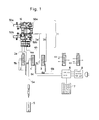
- Fig. 1 shows a schematic structure of the embodiment of the whole creeper system of present invention.
- the numeral 1 denotes a tube creeper
- numeral 2 denotes control valve for extending/contracting arms, which is in the form of 5-port electromagnetic valve for controlling pressure air to extend/contract arms of front and rear support member
- numerals 3 and 4 denote the control valve for front set of arms and rear set of arms respectively, each being in the form of 5-port electromagnetic valve for extending/contracting front set of arms 50a or rear set of arms 50b.
- Pressure air is supplied from a source 5 to the valves 2, 3 and 4 via hoses 5b, 5c, and 5d branched from the hose 5a.
- valves 2, 3, 4 are energized by electric currents via cables 6b, 6c, 6d controlled by the controller 6 and control panel 7. These valves admit air into the hoses 2a, 3a, 4a when they are energized; on the other hand, they admit air into the hoses 2b, 3b, 4b when they are deenergized.
- the other ends of the hoses 2a, 3a, 4a as well as 2b, 3b, 4b are connected to the creeper 1 in order to give the creeper a desired motion by pressure air.
- the hoses 2a, 3a, 4a associate with the air source 5, admitting air into one of the bores to activate the piston.
- the air in the other chamber is exhausted via hoses 2b, 3b, 4b through the valves 2, 3, 4.
- This state lasts until the valves are deenergized.
- the reversed valve position lasts until the valves are reenergized.
- the tube creeper moves into a tube, it is accompanied by the following members; i.e. the valves 2, 3, 4 and hoses 2a, 3a, 4a as well as 2b, 3b, 4b and the hose 5a connected to the valves 2, 3, 4 and to the source 5 and cables 6b, 6c, 6d.
- the pressure air source 5, controller 6 and control panel 7 as well as power source are left out of the tube to control and assist the creeper.
- Fig. 2 shows a front view (a), a rear view (b), a side elevation (c), and a cross-section (d) along the line A-A as viewed from the rear side of the tube creeper.
- the structure of the creeper 1 is described with reference to the Fig. 2(a).
- the numeral 10 denotes a front support member 20, a rear support member, and 30 denotes main spindle connecting the front support member 10 and rear support member 20, one end of which is secured to the front support member 10 with a plurality of threads.
- the numeral 40 denotes a piston-cylinder mechanism for extending/retracting front support member and rear support member; i.e. the rear base member 21 is provided with a piston bore 12 in which is slidably received an extension/retraction piston 41, said bore having an air-tight structure with a cover 44 and a ring 45.
- the piston 41 has damper rings 42, 43 at both sides, and the other end of the piston rod is secured to a stay 16 of front base 11 by means of two sets of elastomer washers 46, 47 and a nut 48.
- the extension/retraction piston bore 12 communicates on one side with a tube coupling 24 for extension through an extension passage provided at one end of the bore, and on the other hand with a contraction coupling 25 through a contraction passage (not shown) (Fig. 2(b)).
- the numeral 51 denotes an arm piston; 52 and 53 denote an elastomeric damper ring; 56 denotes an adapter having a rubber member 57 which is secured to the other end of the piston rod by means of a screw 58; said piston rod being slidably retained on the base 11 by means of a bore cover 54 and threads 55.
- the front base 11 is provided with a bore for slidably receiving the arm piston 51; the bore communicates, on the one hand, with front arm extension coupling 14 via an extension passage 13, on the other hand, with contraction coupling 15 via a contraction passage (not shown).
- the other two arm mechanisms 50a are provided on the front base 11.
- the rear base 21 is provided with three rear arm mechanisms 50b, similar to the front arm mechanism, each piston bore communicating with rear arm extension and rear arm contraction coupling 26, 27.
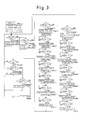
- the creeper is capable of moving in a tube by actuating extension/contraction piston 40 which extends or contracts the front support member 10 and rear support member, and arm extension/contraction mechanism (front arm 50a and rear arm 50b) (see Fig. 3).
- each 5-port electromagnetic valve is set in its initial position for bringing extension/contraction piston 41 in its extended position, and front arm mechanism 50a, rear arm mechanism 50b, i.e. 6 arm pistons, in their contracted position (step 1). Then insert the creeper into the tube. Forward movement is selected on the control panel to start the following cycles according to the program in the control unit 6 (step 2).
- the front arm 50a, as well as the rear arm 50b are extended to see if the arm length is suited for the inner diameter of the tube (replace the adapter 56 if necessary; step 3).
- Rear arms 50a are contracted (step 4).
- Extension/contraction piston 40 is contracted (the rear support member 2 is moved toward the front support member 10; step 5). Extend the rear arm 50b (step 6).
- step 7 Contract the front arms 50a (step 7). Extend extension/contraction piston 40 (move forward the front support member 10 by the stroke length; step 8). Extend the front arms 50a (step 9), (the last step (step 9) is the same as step 3). Step 4 through step 9 are performed in a cycle until the stop order (step 20) is given through control panel 7, realizing step-by-step motion in step 8.
- a timer is started to regulate the speed of movement; the speed is given in the steps 40 through 43; predetermined speed (speed 1 to 3) is selected taking into consideration the reliability of the action of the creeper and the productivity.
- the control unit 6 which gives orders and decides the motion cycles given on the control panel 7 can be in the form of a sequencer of conventional type; for example HD6303XP as CPU,27C64 as memory, TA8000S as reset or other IC can be used.
- the assembler can be used as the language for the program based on the flow chart shown in Fig. 3, the assembler can be used.
- a pair of rotary members 61, 62 are rotatably mounted on the spindle 30, these members having three pivots 64 at their periphery, and three links 63 pivoted at 64 between the rotary members 61, 62 (Fig. 2(d)).
- the arm piston 51 has an axial protuberance 65 extending toward the rotary member 61, 62 at the point remote from the bore cover of the distance equal to the piston stroke, and the end of the link 63 is pivotally secured at its end by means of washer 66 and nut 67 (Fig. 2(a)).
- Other arm pistons 51 have similar link mechanisms, thus axial protuberance 65 on each arm piston and link 63, piston 64, nut 67, and a pair of rotary members 61, 62 constitute a link mechanism for the front support member 10.
- the link mechanism for the rear support member 20 is contructed in the same manner.
- the link mechanism permits three arm pistons 51 to extend or retract in synchronism, i.e. extending or retracting the same distance from the main spindle 30 depending on the angle of rotation of the rotary members 61, 62.
- the creeper is easy to be adapted for tubes of different diameter by using suitable adapter 56.
- the creeper is capable of moving in a tube by actuating extension/contraction piston 40 which extend or contract the front support member 10 and rear support member, and arm extension/contraction mechanism (front arm 50a and rear arm 50b) (see Fig. 3).
- each 5-port electromagnetic valve is set in its initial position for bringing extension/contraction piston 41 in its extended position, and front arm mechanism 50a, rear arm mechanism 50b, i.e. 6 arm pistons, in their contracted position (step 1). Then insert the creeper into the tube. Forward movement is selected on the control panel to start the following cycles according to the program in the control unit 6 (step 2).
- the front arm 50a, as well as the rear arms 50b are extended to see if the arm length is suited for the inner diameter of the tube (replace the adapter 56 if necessary; step 3).
- Rear arms 50a are contracted (step 4).
- Extension/contraction piston 40 is contracted (the rear support member 20 is moved toward the front support member 10; step 5).
- step 9 Extend the front arms 50a (step 9). Since the last step (step 9) is the same as step 3, steps 4 through 9 are performed in a cycle until the stop order (step 20) is given through control panel 7, realizing step-by-step motion in step 8.
- step 6 Extend the rear arm 50b (step 6). Contract the front arms 50a (step 7). Extend extension/contraction piston 40 (move forward the front support member 10 by the stroke length, step 8). Extend the front arms 50a (step 9). Since the last step (step 9) is the same as step 3. Step 4 through step 9 are performed in a cycle until the stop order (step 20) is given through control panel 7, realizing step-by-step motion in step 8.
- a timer is started to regulate the speed of movement; the speed is given in the steps 40 through 43; predetermined speed (speed 1 to 3) is selected taking into consideration the reliability of the action of the creeper and the productivity.
- control panel 7 is provided with keys for forward motion, backward motion, advance, stop, forward speed change, backward speed change, test mode, free mode, the flow-chart in Fig. 3 can be changed or modified on the control panel.
- a pair of rotary members 61, 62 are rotatably mounted on the spindle 30, these members having three pivots 64 at their periphery, and three links 63 pivoted at 64 between the rotary members 61, 62 (Fig. 2(d)).
- the arm piston 51 has an axial protuberance 65 extending toward the rotary members 61, 62 at the point remote from the bore cover of the distance equal to the piston stroke, and the end of the link 63 is pivotally secured at its end by means of washer 66 and nut 67 (Fig. 2(a)).
- the link mechanism for the rear support member 20 is constructed in the same manner.
- three arm pistons 51 extend or retract by the same distance from the main spindle 30 depending on the angle of rotation of the rotary members 61, 62.
- the support mechanism is capable of positioning the main spindle of the apparatus coaxial with a straight tube as well as with a bent tube. Since the minimum radius of a bent tube through which the apparatus 1 can pass depends on the largest distance between the front arms and the rear arms, and the length of arms at their contracted position, suitable apparatus should be selected.
- the apparatus is easy to be adapted for any bent tube by choosing adaptors 56 having suitable dimensions.
- the creeper has a stay at its periphery or a hole 31 coaxial with the main shaft, it can be used mounting various attachments.
- the apparatus can move forward or backward in the manner that one (10) of the support members 10, 20, stretching its arms against tube wall, supports the whole apparatus while the other support member (20) moves forward or backward, then the latter takes turns to support the whole apparatus, while the former moves forward or backward, thus repeating the cycle.
- the step-by-step motion of the apparatus is firm because, either of the arms 50a, 50b at any time grasps the inner surface of the tube.
- the present invention provides suitable stay which endures the reaction force by using a higher pressure or proper piston mechanism having larger cylinder bore.
- the apparatus Since the minimum radius of a bent tube through which the apparatus can pass depends on the largest distance between the front arms and the rear arms, and the length of arms at their contracted position, the apparatus is easy to be adapted for any bent tube by choosing adaptors having suitable dimensions.
- the present invention provides an apparatus capable of moving with high reliability not only in a tube having ununiform diameter but also in a straight or bent tube.
- the present invention provides a method for moving with high reliability in a tube having ununiform diameter as well as in a straight or bent tube.
- the present invention provides an apparatus for firmly driving an equipment for tube inside cleaning operation which brings about forces against tube wall.
- air can be used as pressure media without causing any hazardous effects on the pipeline or water, thus providing an apparatus with easier maintenance and simpler structure.
- air can be used as pressure media without causing any hazardous effects on the pipeline or water, thus providing easier maintenance and simpler structure because of easy exhaustion of air.
- the present invention provides a method of creeping in any bent tubes merely choosing a creeper having proper dimensions.
- the distance of expansion or contraction of each of three arms is kept always equal notwithstanding the change of inner diameter of the tube, not only for a straight tube but also for a bent tube.
- the present invention further enables inspection or observation in a favorable position of tube inner wall with fibre cables installed in a passage provided in a main spindle.
Landscapes
- Engineering & Computer Science (AREA)
- General Engineering & Computer Science (AREA)
- Chemical & Material Sciences (AREA)
- Combustion & Propulsion (AREA)
- Mechanical Engineering (AREA)
- Life Sciences & Earth Sciences (AREA)
- Geology (AREA)
- Mining & Mineral Resources (AREA)
- Physics & Mathematics (AREA)
- Environmental & Geological Engineering (AREA)
- Fluid Mechanics (AREA)
- General Life Sciences & Earth Sciences (AREA)
- Geochemistry & Mineralogy (AREA)
- Investigating Materials By The Use Of Optical Means Adapted For Particular Applications (AREA)
Applications Claiming Priority (6)
| Application Number | Priority Date | Filing Date | Title |
|---|---|---|---|
| JP279457/90 | 1990-10-19 | ||
| JP279456/90 | 1990-10-19 | ||
| JP279455/90 | 1990-10-19 | ||
| JP27945590A JPH04154469A (ja) | 1990-10-19 | 1990-10-19 | 管内移動方法 |
| JP27945690A JPH04154470A (ja) | 1990-10-19 | 1990-10-19 | 管内移動装置 |
| JP27945790A JPH04154471A (ja) | 1990-10-19 | 1990-10-19 | 管内移動装置の支持体構造 |
Publications (1)
| Publication Number | Publication Date |
|---|---|
| EP0484701A1 true EP0484701A1 (fr) | 1992-05-13 |
Family
ID=27336660
Family Applications (1)
| Application Number | Title | Priority Date | Filing Date |
|---|---|---|---|
| EP91117578A Withdrawn EP0484701A1 (fr) | 1990-10-19 | 1991-10-15 | Dispositif capable de se déplacer dans un tuyau; procédé de déplacement dans un tuyau et dispositif de support |
Country Status (2)
| Country | Link |
|---|---|
| EP (1) | EP0484701A1 (fr) |
| CA (1) | CA2053481A1 (fr) |
Cited By (12)
| Publication number | Priority date | Publication date | Assignee | Title |
|---|---|---|---|---|
| WO1994018679A1 (fr) * | 1993-02-01 | 1994-08-18 | Siemens Aktiengesellschaft | Element de transport pouvant avancer automatiquement a l'interieur d'un tuyau |
| EP0638757A1 (fr) * | 1993-08-13 | 1995-02-15 | Daimler-Benz Aerospace Aktiengesellschaft | Appareil d'examen et/ou de réparation de canaux |
| US5473953A (en) * | 1993-07-09 | 1995-12-12 | The United States Of America As Represented By The United States Department Of Energy | Device for inspecting vessel surfaces |
| US7131344B2 (en) * | 2002-03-13 | 2006-11-07 | Burn-Am Co., Ltd. | Device and method for inspecting inside of underground pipe line and method of inspecting concrete on inside of underground pipe line for deterioration |
| EP2136374A1 (fr) * | 2008-06-17 | 2009-12-23 | GE-Hitachi Nuclear Energy Americas LLC | Outillage destiné à l'inspection et/ou au traitement à distance de la surface interne de tuyauteries ou de récipients de forme allongée, en particulier dans le circuit de refroidissement d'un réacteur nucléaire, et procédé d'utilisation d'un tel outillage |
| CN102862617A (zh) * | 2012-07-02 | 2013-01-09 | 上海大学 | 废墟狭缝搜救机器人头部拉进机构 |
| RU2509255C1 (ru) * | 2012-11-14 | 2014-03-10 | Владимир Евгеньевич Скворцов | Автономное внутритрубное транспортное устройство |
| CN107042993A (zh) * | 2017-04-27 | 2017-08-15 | 安徽信陆电子科技有限公司 | 移动载座 |
| CN107380931A (zh) * | 2017-06-28 | 2017-11-24 | 安徽信陆电子科技有限公司 | 一种无尘车间快速运输通道 |
| FR3100857A1 (fr) * | 2019-09-16 | 2021-03-19 | Autonomous Clean Water Appliance (Acwa) Robotics | Robot d’exploration de conduit comprenant un module de prise d’appui |
| CN112845429A (zh) * | 2021-01-14 | 2021-05-28 | 贵州大学 | 一种隧道排水管道除晶去堵装置 |
| CN115370868A (zh) * | 2022-07-13 | 2022-11-22 | 常州工学院 | 一种适用于不规则管道的变构机器人 |
Families Citing this family (1)
| Publication number | Priority date | Publication date | Assignee | Title |
|---|---|---|---|---|
| CN113276981B (zh) * | 2020-02-19 | 2022-06-17 | 广东博智林机器人有限公司 | 爬行车及钢筋绑扎机器人 |
Citations (4)
| Publication number | Priority date | Publication date | Assignee | Title |
|---|---|---|---|---|
| DE1625962A1 (de) * | 1967-11-16 | 1970-08-06 | Crc Crose Int Inc | Rohr-Mitlauf-Vorrichtung |
| EP0145266A2 (fr) * | 1983-11-07 | 1985-06-19 | Costain Streeter Lining Limited | Appareil de revêtement de l'intérieur des tubes par pulvérisation rotative |
| DE3829894A1 (de) * | 1988-09-02 | 1990-03-08 | Condux Maschinenbau Gmbh & Co | Hydraulisch betaetigter vorschubstempel |
| FR2638813A1 (fr) * | 1988-11-09 | 1990-05-11 | Nancy Ecole Sup Sciences Techn | Vehicule autopropulse pour meulage de tuyauterie |
-
1991
- 1991-10-15 CA CA 2053481 patent/CA2053481A1/fr not_active Abandoned
- 1991-10-15 EP EP91117578A patent/EP0484701A1/fr not_active Withdrawn
Patent Citations (4)
| Publication number | Priority date | Publication date | Assignee | Title |
|---|---|---|---|---|
| DE1625962A1 (de) * | 1967-11-16 | 1970-08-06 | Crc Crose Int Inc | Rohr-Mitlauf-Vorrichtung |
| EP0145266A2 (fr) * | 1983-11-07 | 1985-06-19 | Costain Streeter Lining Limited | Appareil de revêtement de l'intérieur des tubes par pulvérisation rotative |
| DE3829894A1 (de) * | 1988-09-02 | 1990-03-08 | Condux Maschinenbau Gmbh & Co | Hydraulisch betaetigter vorschubstempel |
| FR2638813A1 (fr) * | 1988-11-09 | 1990-05-11 | Nancy Ecole Sup Sciences Techn | Vehicule autopropulse pour meulage de tuyauterie |
Cited By (15)
| Publication number | Priority date | Publication date | Assignee | Title |
|---|---|---|---|---|
| WO1994018679A1 (fr) * | 1993-02-01 | 1994-08-18 | Siemens Aktiengesellschaft | Element de transport pouvant avancer automatiquement a l'interieur d'un tuyau |
| US5473953A (en) * | 1993-07-09 | 1995-12-12 | The United States Of America As Represented By The United States Department Of Energy | Device for inspecting vessel surfaces |
| EP0638757A1 (fr) * | 1993-08-13 | 1995-02-15 | Daimler-Benz Aerospace Aktiengesellschaft | Appareil d'examen et/ou de réparation de canaux |
| US7131344B2 (en) * | 2002-03-13 | 2006-11-07 | Burn-Am Co., Ltd. | Device and method for inspecting inside of underground pipe line and method of inspecting concrete on inside of underground pipe line for deterioration |
| EP2136374A1 (fr) * | 2008-06-17 | 2009-12-23 | GE-Hitachi Nuclear Energy Americas LLC | Outillage destiné à l'inspection et/ou au traitement à distance de la surface interne de tuyauteries ou de récipients de forme allongée, en particulier dans le circuit de refroidissement d'un réacteur nucléaire, et procédé d'utilisation d'un tel outillage |
| CN102862617A (zh) * | 2012-07-02 | 2013-01-09 | 上海大学 | 废墟狭缝搜救机器人头部拉进机构 |
| RU2509255C1 (ru) * | 2012-11-14 | 2014-03-10 | Владимир Евгеньевич Скворцов | Автономное внутритрубное транспортное устройство |
| CN107042993A (zh) * | 2017-04-27 | 2017-08-15 | 安徽信陆电子科技有限公司 | 移动载座 |
| CN107380931A (zh) * | 2017-06-28 | 2017-11-24 | 安徽信陆电子科技有限公司 | 一种无尘车间快速运输通道 |
| FR3100857A1 (fr) * | 2019-09-16 | 2021-03-19 | Autonomous Clean Water Appliance (Acwa) Robotics | Robot d’exploration de conduit comprenant un module de prise d’appui |
| WO2021052869A1 (fr) | 2019-09-16 | 2021-03-25 | Autonomous Clean Water Appliance (Acwa) Robotics | Robot d'exploration de conduit comprenant un module de prise d'appui |
| US12140261B2 (en) * | 2019-09-16 | 2024-11-12 | Autonomous Clean Water Appliance (Acwa) Robotics | Conduit-exploring robot comprising a bearing module |
| CN112845429A (zh) * | 2021-01-14 | 2021-05-28 | 贵州大学 | 一种隧道排水管道除晶去堵装置 |
| CN112845429B (zh) * | 2021-01-14 | 2022-08-12 | 贵州大学 | 一种隧道排水管道除晶去堵装置 |
| CN115370868A (zh) * | 2022-07-13 | 2022-11-22 | 常州工学院 | 一种适用于不规则管道的变构机器人 |
Also Published As
| Publication number | Publication date |
|---|---|
| CA2053481A1 (fr) | 1992-05-20 |
Similar Documents
| Publication | Publication Date | Title |
|---|---|---|
| EP0484701A1 (fr) | Dispositif capable de se déplacer dans un tuyau; procédé de déplacement dans un tuyau et dispositif de support | |
| US6427602B1 (en) | Pipe crawler apparatus | |
| KR100934806B1 (ko) | 주행성능과 중심일체성이 향상된 배관 작업 로봇 | |
| CN108223968B (zh) | 一种自主式小型管道机器人 | |
| CN100408281C (zh) | 用于多轴操纵器的通用机械手 | |
| CN110486570A (zh) | 一种仿生管道爬行机器人 | |
| CN206514004U (zh) | 气动管道机器人 | |
| CN105757398A (zh) | 基于气动肌腱气动管道机器人系统 | |
| KR20080109378A (ko) | 배관의 내부 탐사 및 작업용 로봇 | |
| CN102393308B (zh) | 用于汽车试验的驾驶机器人 | |
| JPH08501752A (ja) | 管内を自走可能な搬送手段 | |
| CN108343803A (zh) | 气动管道机器人 | |
| US20260002624A1 (en) | Apparatus for Propulsion and Operations Inside a Cylindrical Body | |
| CN1281889C (zh) | 蠕动式管道爬行器 | |
| CN208074397U (zh) | 一种管径调节机构 | |
| CN212960430U (zh) | 一种用于细小管道检修的串联式爬行机器人 | |
| CS216680B2 (en) | Rotary tubular points | |
| CN117782866B (zh) | 一种软管挠曲疲劳试验台 | |
| KR100766791B1 (ko) | 관로 디스케일링장치 | |
| JP2547181B2 (ja) | 管内走行体 | |
| CN109282108A (zh) | 一种用于管道检测的载具机器人 | |
| CN223090262U (zh) | 管道非开挖修复套筒装置 | |
| RU2023619C1 (ru) | Транспортное средство для перемещения по наружным поверхностям трубопроводов | |
| CN211439960U (zh) | 一种曲臂式巡线机器人 | |
| JP2002168743A (ja) | 供試体に荷重を与える試験装置 |
Legal Events
| Date | Code | Title | Description |
|---|---|---|---|
| PUAI | Public reference made under article 153(3) epc to a published international application that has entered the european phase |
Free format text: ORIGINAL CODE: 0009012 |
|
| AK | Designated contracting states |
Kind code of ref document: A1 Designated state(s): CH DE FR GB IT LI |
|
| 17P | Request for examination filed |
Effective date: 19920826 |
|
| STAA | Information on the status of an ep patent application or granted ep patent |
Free format text: STATUS: THE APPLICATION IS DEEMED TO BE WITHDRAWN |
|
| 18D | Application deemed to be withdrawn |
Effective date: 19940503 |
|
| K1C1 | Correction of patent application (title page) published |
Effective date: 19920513 |