EP0484705A1 - Dispositif pour le remplissage de saucisses - Google Patents
Dispositif pour le remplissage de saucisses Download PDFInfo
- Publication number
- EP0484705A1 EP0484705A1 EP91117608A EP91117608A EP0484705A1 EP 0484705 A1 EP0484705 A1 EP 0484705A1 EP 91117608 A EP91117608 A EP 91117608A EP 91117608 A EP91117608 A EP 91117608A EP 0484705 A1 EP0484705 A1 EP 0484705A1
- Authority
- EP
- European Patent Office
- Prior art keywords
- filling
- filling cylinder
- piston
- cylinder
- mass
- Prior art date
- Legal status (The legal status is an assumption and is not a legal conclusion. Google has not performed a legal analysis and makes no representation as to the accuracy of the status listed.)
- Withdrawn
Links
- 235000013580 sausages Nutrition 0.000 title claims abstract description 26
- 235000013372 meat Nutrition 0.000 claims abstract description 28
- 239000000945 filler Substances 0.000 claims description 17
- 238000003860 storage Methods 0.000 claims description 17
- 230000033001 locomotion Effects 0.000 description 4
- 238000004140 cleaning Methods 0.000 description 3
- 238000010586 diagram Methods 0.000 description 3
- 230000010006 flight Effects 0.000 description 3
- 238000004519 manufacturing process Methods 0.000 description 3
- 238000009423 ventilation Methods 0.000 description 3
- 238000005273 aeration Methods 0.000 description 2
- 230000005484 gravity Effects 0.000 description 2
- 230000007704 transition Effects 0.000 description 2
- 241000237858 Gastropoda Species 0.000 description 1
- 230000005540 biological transmission Effects 0.000 description 1
- 238000010276 construction Methods 0.000 description 1
- 238000009826 distribution Methods 0.000 description 1
- 230000003670 easy-to-clean Effects 0.000 description 1
- 230000000694 effects Effects 0.000 description 1
- 238000005516 engineering process Methods 0.000 description 1
- 239000000314 lubricant Substances 0.000 description 1
- 238000000034 method Methods 0.000 description 1
- 238000003825 pressing Methods 0.000 description 1
- 238000009489 vacuum treatment Methods 0.000 description 1
Images


Classifications
-
- A—HUMAN NECESSITIES
- A22—BUTCHERING; MEAT TREATMENT; PROCESSING POULTRY OR FISH
- A22C—PROCESSING MEAT, POULTRY, OR FISH
- A22C11/00—Sausage making ; Apparatus for handling or conveying sausage products during manufacture
- A22C11/02—Sausage filling or stuffing machines
- A22C11/08—Sausage filling or stuffing machines with pressing-worm or other rotary-mounted pressing-members
Definitions
- the filling cylinder can be arranged vertically with the filling nozzle on top or horizontally.
- the second end of the filling cylinder can be closed by a cover on which the filling nozzle is firmly attached.
- the filling cylinders are loaded with the piston in the end position.
- the lid is removed from the second end and the meat is filled through the second end into the filling cylinder, which is carried out either manually or with the aid of a filling device.
- the loss times for filling are considerable, and the known device can therefore only be operated with large interruptions.
- the throughput is due to this discontinuous operation and the filling capacity is very low, so that such a device is not suitable for large filling capacities.
- a filling system For large filling capacities, a filling system has been developed that works with a large number of filling cylinders.
- a separate loading station at which a filling device is provided, vacuumed sausage meat is pressed into the filling cylinder which is open at both ends and which is arranged horizontally.
- the cylinder which is open on both ends and filled with sausage meat, is transported after filling with transport devices to a filling station, in which the sausage meat is pressed from the filling cylinder into a filler neck by a piston.
- this known system there is a certain loss of time due to the cylinder change at the filling station, but this loss of time is partly compensated for by the previous filling at the loading station due to the assembly line operation.
- this known system is limited by the consistency of the meat. Due to the open cylinders on the front sides, the sausage meat must not start to flow due to the influence of gravity. When changing the filling cylinder, the meat surfaces must be brought against each other air-free and flat, because otherwise undesirable air pockets in the filled sausage are unavoidable.
- a filling device which also works with horizontal filling cylinders.
- the filling cylinders are transported back and forth between a loading station and a filling station.
- the distance between the loading station and the filling station is smaller, which means that the transport times can be shortened. This is achieved by means of an automatic two-cylinder change system.
- Another advantage of this device is that it works more hygienically than the system described above, since the filled cylinders are not transported unprotected.
- this device which is also constructed in the manner of a system, requires a comparatively large amount of space.
- this known device also has the same procedural restrictions as the system described above.
- the sausage meat surfaces must be brought flat and flat against each other during the filling cylinder change.
- changing the grade and cleaning are also very time-consuming.
- not insignificant, non-fillable residual quantities arise for the same reason as in the system described above.
- the object of the invention is to improve a device of the type mentioned in such a way that the effort and the manufacturing costs and the required space are reduced, the loss times are reduced and the previously mentioned procedural disadvantages of the prior art can be avoided.
- the device according to the invention should be suitable for use in smaller factories, easy to clean, and flexible in terms of type change and placement in the production area and achieve a good filling result largely independent of the roast consistency, that is to say even with flowing roasts, without any noteworthy, non-fillable residual quantities attack.
- the conveying device should preferably connect the filling device to the first end of the filling cylinder such that the mass from the filling device past the piston in the end position into the filling cylinder is promoted.
- This embodiment is particularly expedient because the first end at which the piston is guided into the filling cylinder is also used to fill the filling cylinder.
- the filling device the conveying device, the filling cylinder and the filling nozzle should be arranged together on a machine frame.
- the conveying device has a feed screw which is directed towards the filling cylinder and is arranged such that it can rotate.
- a screw conveyor is suitable for a particularly gentle conveying of the mass from the filling device to the filling cylinder.
- the feed screw can be arranged at an angle to the axis of the filling cylinder. This arrangement is particularly advantageous if the feed through the first end of the filling cylinder takes place from the rear, since the feed screw extends essentially into the rear space of the device, which is required anyway for the piston and its drive.
- the feed screw can be substantially aligned with the filling cylinder and can contain a cavity which is at least open towards the filling cylinder and within which the piston is movably arranged.
- This embodiment is particularly advantageous in that it strives for compactness with the procedural advantage of a flow of the mass that is as straight as possible, i.e. with minimized deflections and thus the lowest mechanical loads on the product.
- the feed screw and the piston are expediently arranged concentrically to one another.
- a cone attached to the first end of the filling cylinder, the inside diameter of which widens at least to the outside diameter of the feeding screw, and the piston in its end position can be provided between the filling cylinder and the feed screw outside of the filling cylinder at a distance from this.
- the piston In its end position, the piston is preferably essentially completely retracted into the cavity of the screw conveyor. With the help of the cone, an annular opening is created surrounding the piston, through which the mass released by the screw conveyor can enter the filling cylinder.
- the conveying device has an outlet opening which is closed by a closure member when the piston moves from its end position into the filling cylinder.
- a sleeve which is arranged coaxially to the filling cylinder and can be moved in its longitudinal direction and through which the piston can be moved can be provided as the closure member.
- the piston can alternatively be provided with an elongated cylindrical body, the length of which is dimensioned such that it acts as a closure member when the piston is in its end position in the filling cylinder is moved into it.
- the filling of the filling cylinder with mass is particularly easy if it is put under negative pressure in the meantime.
- the filling device preferably has a storage funnel which can be closed by a cover and in which a negative pressure is generated after the cover is closed in order to vent the mass.
- the filler neck can be closed by an outlet slide.
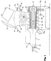
- a first embodiment of a filling device is shown schematically in cross section. With the help of the filling device shown, sausage and meat masses and, in particular, smear-sensitive sausage meat should be filled.
- the filling device contains a filling cylinder 1, which is arranged horizontally in the embodiment shown.
- the filling cylinder 1 is open to its two end faces. 1, a cone 2a is attached, which tapers the inner cross section of the filling cylinder 1 to a smaller cross section and on which a filler neck is arranged Section of the filling cylinder 1 tapers to a smaller cross section and on which a filler neck is arranged.
- the filler neck can be closed with an outlet slide 3.
- a piston 4 On the side of the filling cylinder 1 opposite the filling nozzle 2, a piston 4 is arranged, which can be moved into the latter by a hydraulic drive 5 through the open front side of the filling cylinder 1 opposite the filling nozzle 2, as shown in FIG. 1.
- a hydraulic drive 5 Through the open front side of the filling cylinder 1 opposite the filling nozzle 2, as shown in FIG. 1.
- the piston 4 In Fig. 1 the piston 4 is shown in its end position outside the filling cylinder 1.
- a cylindrical body 4a is formed on the piston 4 and has the same outer diameter as the piston 4.
- a feed screw 6 is provided which is rotatably mounted on bearings 20 within a screw housing 6a.
- the feed screw 6 has a cylindrical hollow body which is open towards its two end faces.
- the piston 4 is arranged inside the cavity 6b of the feed screw 6 thus formed, as can be seen in FIG. 1.
- the piston 4 can be moved out of the hollow feed screw 6 into the filling cylinder 1 by means of the hydraulic drive 5. Therefore, the diameter of the cavity 6b in the feed screw 6 must not be smaller than the outer diameter of the piston 4 and the cylindrical body 4a.
- the filling cylinder 1, the filling nozzle 2, the piston 4 with its cylindrical piston are located 4 with the cylindrical body 4a are arranged concentrically to each other.
- the outside diameter of the piston 4 essentially corresponds to the inside diameter of the filling cylinder 1. Since the outside diameter of the feed screw 6 and thus the inside diameter of the screw housing 6a is substantially larger than the inside diameter of the filling cylinder 1, the filling cylinder 1 is attached to the screw housing 6a via a cone 18, to create a transition from the smaller inner diameter of the filling cylinder 1 to the larger inner diameter of the screw housing 6a.
- An annular opening 18a is formed at the transition between the cone 18 and the screw housing 6a between the latter and the feed screw 6. This opening 18a serves as an outlet opening for the screw housing 6a or inlet opening for the filling cylinder 1.
- a motor 7 is provided for driving the feed screw 6, the rotor shaft of which is coupled to the feed screw 6 via a gear transmission 7a.
- the screw housing 6a opens to a storage hopper 8 sitting thereon, which can be closed by a cover 9 which is hinged to the upper part of the storage hopper 8 via a hinge 10.
- a corresponding drive 11 is provided for opening and closing the cover 9.
- the storage hopper 8 is filled from a sausage car 12, which is shown in FIG. 1 in the upturned position with the lid 9 open.
- the sausage meat can also be introduced into the storage hopper 8 via an inlet valve 13.
- a vacuum pump 14 is connected to the interior of the storage funnel 8 via a vacuum valve 15.
- An aeration valve 16 is also provided on the storage hopper 8. of the supply funnel 8 connected.
- An aeration valve 16 is also provided on the storage hopper 8.
- a vent valve 17 is provided on the filling cylinder 1, namely at its end adjacent to the cone 2a.
- the filling cylinder 1, the filler neck 2, the cone 18, the screw housing 6a and the funnel 8 essentially form a structural unit which is mounted on a machine frame 21. Accordingly, the filling cylinder 1, the filling nozzle 2, the piston 4, the feed screw 6 and the funnel 8 are arranged in a fixed manner relative to one another, although the piston 4 - as described above - can be reciprocally moved in the longitudinal direction of the filling cylinder 2.
- the storage hopper 8 can now be filled with the sausage meat 22 to be filled in that it is sucked in through the inlet valve 13 due to the negative pressure prevailing in the interior of the storage hopper 8.
- the filling can also take place from a container or a sausage car 12, as indicated in FIG. 1.
- the negative pressure in the storage hopper 8 is eliminated by the vacuum valve 15 being closed and the ventilation valve 16 is opened.
- the cover 9 is swung open on the cover hinge 10 by means of the drive 11.
- the meat 22 is now poured from the overturned meat car 12 into the storage hopper 8.
- the lid 9 is closed again and the interior of the storage funnel 8, after opening the vacuum valve 15 and closing the ventilation valve 16, is placed under negative pressure with the aid of the vacuum pump 14.
- the sausage meat 22 which is under vacuum in the storage hopper 8, enters the screw flights of the feed screw 6 underneath it by gravity promoted, inserted through the annular opening 18a in this and further pressed into the filling cylinder 1 through this.
- the vent valve 17 on the filling cylinder 1 is opened, so that the filling cylinder 1 together with the storage funnel 8 is under negative pressure. This enables gentle conveying of the sausage meat, since only the frictional forces in the filling cylinder 1 have to be overcome.
- the filler neck 2 remains closed by the outlet slide 3 during the entire filling phase.
- the vent valve 17 is closed.
- the sausage meat located in the closed space, formed by the closed outlet slide 3, the filling cylinder 1 and the piston 4, is now moved by a forward movement of the piston 4 from its end position shown in FIG. 1 into the filling cylinder 1 of the hydraulic drive 5 compressed to a preselected pressure.
- the annular opening 18a is closed by the cylindrical body 4a attached to the piston 4 in that the cylindrical body 4a connects the filling cylinder 1 to the feed screw 6.
- the length of the cylindrical body 4a is dimensioned such that its rear end (on the right according to FIG. 1) is still inside the feed screw 6 and thus closes the annular opening 18a to the screw flights on the outside of the feed screw 6, when the piston 4 has reached its foremost position within the filling cylinder 1 on the cone 2a.
- FIG. 2 differs from the embodiment according to FIG. 1 in that the piston 4 has no cylindrical body 4a and a sleeve-shaped closure element 19 is arranged concentrically between the piston 4 and the inside of the feed screw 6 in the cavity 6b thereof. 2, the closure element 19 is shown in its end position, in which it is completely retracted into the cavity 6b of the feed screw 6.
- the sleeve-shaped closure member 19 is moved from the position shown in FIG. 2 into the cone 18 and forms an extension of the filling cylinder 1 up to the feed screw 6 and thus to the piston 4 in the end position.
- the annular opening 18a closed to the screw flights in order to completely prevent the sausage meat from flowing back out of the filling cylinder 1 into the feed screw 6 during the first forward movement of the piston 4.
- the embodiment shown in FIG. 3 differs from the embodiment according to FIG. 2 in that the feed screw is not arranged concentrically with the piston 4, but at an angle to the axis of the filling cylinder 1.
- An extension 18 ' is attached to the end of the filling cylinder 1 opposite the filler neck 2, which has a first opening 18a' for the piston 4 and the sleeve-shaped closure member 19 and a lateral opening 18b 'for the feed screw 6'.
- the associated screw housing 6a' extends at the same angle to the axis of the filling cylinder 1, namely to the rear above the piston 4 in its end position.
- the loading from the rear has the advantage that the feed screw 6 extends with its Snail housing 6a 'in the back room extends, which is required for the piston 4 and its hydraulic drive 5 anyway.
- the sleeve-shaped closure member 19 can alternatively be arranged in the extension 18 'in the longitudinal direction immovably, but rotatably and contain an opening which is brought into line with the side opening 18b' for filling the filling cylinder 1, while for filling that sleeve-shaped closure member is rotated accordingly, whereby the side opening 18b 'is closed by the wall of the closure member.
Landscapes
- Life Sciences & Earth Sciences (AREA)
- Engineering & Computer Science (AREA)
- Wood Science & Technology (AREA)
- Zoology (AREA)
- Food Science & Technology (AREA)
- Processing Of Meat And Fish (AREA)
Applications Claiming Priority (2)
| Application Number | Priority Date | Filing Date | Title |
|---|---|---|---|
| DE19904035012 DE4035012A1 (de) | 1990-11-03 | 1990-11-03 | Vorrichtung zum abfuellen von massen, insbesondere wurst- und fleischmassen |
| DE4035012 | 1990-11-03 |
Publications (1)
| Publication Number | Publication Date |
|---|---|
| EP0484705A1 true EP0484705A1 (fr) | 1992-05-13 |
Family
ID=6417594
Family Applications (1)
| Application Number | Title | Priority Date | Filing Date |
|---|---|---|---|
| EP91117608A Withdrawn EP0484705A1 (fr) | 1990-11-03 | 1991-10-16 | Dispositif pour le remplissage de saucisses |
Country Status (2)
| Country | Link |
|---|---|
| EP (1) | EP0484705A1 (fr) |
| DE (1) | DE4035012A1 (fr) |
Cited By (5)
| Publication number | Priority date | Publication date | Assignee | Title |
|---|---|---|---|---|
| FR2912598A1 (fr) * | 2007-02-21 | 2008-08-22 | Faf Soc Par Actions Simplifiee | Machine de dosage et de distribution d'un produit alimentaire a des fins de gavage. |
| EP2062478A1 (fr) * | 2007-11-20 | 2009-05-27 | Albert Handtmann Maschinenfabrik GmbH & Co. KG | Machine de remplissage et procédé de remplissage |
| KR100909534B1 (ko) | 2007-09-11 | 2009-07-27 | 노형준 | 소시지 제조기 |
| USD780346S1 (en) | 2012-01-12 | 2017-02-28 | Tuf-Tite, Inc. | Sidewalk tile |
| US10920378B2 (en) | 2018-01-19 | 2021-02-16 | Tuf-Tite, Inc. | Stamped steel detectable warning tile and method of manufacture |
Citations (4)
| Publication number | Priority date | Publication date | Assignee | Title |
|---|---|---|---|---|
| US3147784A (en) * | 1961-03-14 | 1964-09-08 | Mayer & Co Inc O | Apparatus for deaerating and feeding ground meat mixture from a vacuum chamber |
| FR2069723A5 (fr) * | 1969-11-29 | 1971-09-03 | Javaloy Jose | |
| FR2415575A1 (fr) * | 1978-01-27 | 1979-08-24 | Nagema Veb K | Dispositif pour soutirer des produits pateux |
| SU862885A1 (ru) * | 1980-01-03 | 1981-09-15 | Ленинградское Научно-Производственное Объединение По Созданию И Внедрению Технологического Оборудования,Средств Механизации И Автоматизации Производства Мясной И Молочной Промышленности | Шприц-дозатор дл наполнени фаршем колбасных оболочек |
Family Cites Families (1)
| Publication number | Priority date | Publication date | Assignee | Title |
|---|---|---|---|---|
| DE1831115U (de) * | 1959-12-12 | 1961-05-10 | Vemag Verdener Masch App | Vorrichtung zum abteilen und einfuellen breiiger massen in schlauchartige behaelter, insbesondere von wurstbraet in daerme. |
-
1990
- 1990-11-03 DE DE19904035012 patent/DE4035012A1/de not_active Withdrawn
-
1991
- 1991-10-16 EP EP91117608A patent/EP0484705A1/fr not_active Withdrawn
Patent Citations (4)
| Publication number | Priority date | Publication date | Assignee | Title |
|---|---|---|---|---|
| US3147784A (en) * | 1961-03-14 | 1964-09-08 | Mayer & Co Inc O | Apparatus for deaerating and feeding ground meat mixture from a vacuum chamber |
| FR2069723A5 (fr) * | 1969-11-29 | 1971-09-03 | Javaloy Jose | |
| FR2415575A1 (fr) * | 1978-01-27 | 1979-08-24 | Nagema Veb K | Dispositif pour soutirer des produits pateux |
| SU862885A1 (ru) * | 1980-01-03 | 1981-09-15 | Ленинградское Научно-Производственное Объединение По Созданию И Внедрению Технологического Оборудования,Средств Механизации И Автоматизации Производства Мясной И Молочной Промышленности | Шприц-дозатор дл наполнени фаршем колбасных оболочек |
Cited By (6)
| Publication number | Priority date | Publication date | Assignee | Title |
|---|---|---|---|---|
| FR2912598A1 (fr) * | 2007-02-21 | 2008-08-22 | Faf Soc Par Actions Simplifiee | Machine de dosage et de distribution d'un produit alimentaire a des fins de gavage. |
| KR100909534B1 (ko) | 2007-09-11 | 2009-07-27 | 노형준 | 소시지 제조기 |
| EP2062478A1 (fr) * | 2007-11-20 | 2009-05-27 | Albert Handtmann Maschinenfabrik GmbH & Co. KG | Machine de remplissage et procédé de remplissage |
| USD780346S1 (en) | 2012-01-12 | 2017-02-28 | Tuf-Tite, Inc. | Sidewalk tile |
| USD858805S1 (en) | 2012-01-12 | 2019-09-03 | Tuf-Tite, Inc. | Sidewalk tile |
| US10920378B2 (en) | 2018-01-19 | 2021-02-16 | Tuf-Tite, Inc. | Stamped steel detectable warning tile and method of manufacture |
Also Published As
| Publication number | Publication date |
|---|---|
| DE4035012A1 (de) | 1992-05-07 |
Similar Documents
| Publication | Publication Date | Title |
|---|---|---|
| DE69516640T2 (de) | Verfahren und Vorrichtung zur Herstellung von Getreideaggregaten auf industrieller Basis | |
| EP0185958B1 (fr) | Procédé et dispositif pour doser un produit s'écoulant facilement | |
| DE69817279T2 (de) | Vorrichtung zur Füllung der Formen in Pressen zur Herstellung von Fliesen und Ausführungsmittel dafür | |
| DE2122858B2 (de) | Einrichtung zum pneumatischen bilden und foerdern von durch druckluftpolster voneinander getrennten materialpfropfen in einer leitung | |
| DE2924313C2 (de) | Vorrichtung zum Füllen von pulverisiertem Füllgut in einen Sack | |
| DE1911485U (de) | Vorrichtung zum austragen von schuettguetern. | |
| DE1812291B2 (de) | Vorrichtung zum bilden weitgehend gewichtsgleicher tabakportionen | |
| DE69010188T2 (de) | Vorrichtung zum dosieren von erzeugnissen in pastenform, insbesondere fleisch oder sonstigen proteinemulsionen. | |
| DE2543379A1 (de) | Vorrichtung zur kontinuierlichen herstellung von angemachtem moertel | |
| EP0484705A1 (fr) | Dispositif pour le remplissage de saucisses | |
| DE3909566A1 (de) | Verfahren und vorrichtung zum verpacken und pressen von faserflocke | |
| EP0928555A1 (fr) | Dispositif et procédé pour doser un matériau fibreux | |
| DE69606962T2 (de) | Verarbeitungsteil in einer Verarbeitungseinheit zum Beschichten von Samen mit einem Gel | |
| DE69909368T2 (de) | Anlage zur Herstellung von Materialien für Spritzguss- und Formpressverfahren | |
| DE10046127A9 (de) | Verfahren zum verfuellen von mikroisiertem pulver und vorrichtung zum durchfuehren des verfahrens | |
| EP0401510B1 (fr) | Dispositif pour remplir des emballages de produits pouvant s'écouler | |
| DE10046127A1 (de) | Verfahren zum Verfüllen von mikroisiertem Pulver und Vorrichtung zum Durchführen des Verfahrens | |
| DE2218864C3 (de) | Vorrichtung zum dosierten Abfüllen von Flüssigkeiten wie Milch u.dgl | |
| DE3431274C2 (de) | Austrittsdüse | |
| DE2523374A1 (de) | Vorrichtung zur kontinuierlichen herstellung von angemachtem moertel | |
| AT381721B (de) | Transporteinrichtung fuer weintrauben | |
| EP0235520B1 (fr) | Dispositif pour le remplissage d'un produit transformable et fluide | |
| EP4190530B1 (fr) | Dispositif d'alimentation en caoutchouc, en particulier en caoutchouc de silicone solide, par exemple une extrudeuse | |
| AT389911B (de) | Vorrichtung zum herstellen verarbeitungsbereiten nassestrichs | |
| AT256712B (de) | Vorrichtung zum Austragen von Schüttgütern |
Legal Events
| Date | Code | Title | Description |
|---|---|---|---|
| PUAI | Public reference made under article 153(3) epc to a published international application that has entered the european phase |
Free format text: ORIGINAL CODE: 0009012 |
|
| AK | Designated contracting states |
Kind code of ref document: A1 Designated state(s): AT CH DE ES FR GB IT LI NL |
|
| 17P | Request for examination filed |
Effective date: 19921107 |
|
| STAA | Information on the status of an ep patent application or granted ep patent |
Free format text: STATUS: THE APPLICATION HAS BEEN WITHDRAWN |
|
| 18W | Application withdrawn |
Withdrawal date: 19931103 |