EP0484739A2 - Dispositif pour appareil de développement continu - Google Patents
Dispositif pour appareil de développement continu Download PDFInfo
- Publication number
- EP0484739A2 EP0484739A2 EP91118037A EP91118037A EP0484739A2 EP 0484739 A2 EP0484739 A2 EP 0484739A2 EP 91118037 A EP91118037 A EP 91118037A EP 91118037 A EP91118037 A EP 91118037A EP 0484739 A2 EP0484739 A2 EP 0484739A2
- Authority
- EP
- European Patent Office
- Prior art keywords
- conveyor belt
- roller
- rollers
- insert
- squeezing
- Prior art date
- Legal status (The legal status is an assumption and is not a legal conclusion. Google has not performed a legal analysis and makes no representation as to the accuracy of the status listed.)
- Granted
Links
Images

Classifications
-
- G—PHYSICS
- G03—PHOTOGRAPHY; CINEMATOGRAPHY; ANALOGOUS TECHNIQUES USING WAVES OTHER THAN OPTICAL WAVES; ELECTROGRAPHY; HOLOGRAPHY
- G03D—APPARATUS FOR PROCESSING EXPOSED PHOTOGRAPHIC MATERIALS; ACCESSORIES THEREFOR
- G03D15/00—Apparatus for treating processed material
- G03D15/02—Drying; Glazing
-
- G—PHYSICS
- G03—PHOTOGRAPHY; CINEMATOGRAPHY; ANALOGOUS TECHNIQUES USING WAVES OTHER THAN OPTICAL WAVES; ELECTROGRAPHY; HOLOGRAPHY
- G03D—APPARATUS FOR PROCESSING EXPOSED PHOTOGRAPHIC MATERIALS; ACCESSORIES THEREFOR
- G03D3/00—Liquid processing apparatus involving immersion; Washing apparatus involving immersion
- G03D3/08—Liquid processing apparatus involving immersion; Washing apparatus involving immersion having progressive mechanical movement of exposed material
- G03D3/12—Liquid processing apparatus involving immersion; Washing apparatus involving immersion having progressive mechanical movement of exposed material for plates, films or prints spread onto belt conveyors
Definitions
- the invention relates to an insert for continuous processing devices according to the preamble of patent claim 1.
- German patent DE-PS 26 09 463 An insert of this type, as is known from German patent DE-PS 26 09 463, is used for developing films or generally photo materials. It is customary to convey the photographic material successively through several individual tanks in which various liquid chemicals are located. For complete development, the photographic material must therefore be transferred from a single tank to the subsequent single tank and conveyed.
- German patent DE-PS 26 09 463 provides for the use of a single endless conveyor belt for use.
- This endless conveyor belt extends over the full width of the transport rollers, which are arranged in pairs on the input and output sides of the insert, the roller on the output side acting as a squeeze roller.
- the film material is in its full width at the exit from a single tank squeezed or squeezed out, which may otherwise be film material of different widths.
- the rollers arranged in pairs on the outlet side of the insert form a squeezing station, in that the roller below acts as a squeeze roller.
- the invention has for its object to improve the use of the type described in the preamble of claim 1 and known by the German patent DE-PS 26 09 463 so that an optimal development of the film material is possible, and that when the film material enters from one Single tank in the next one Single tank no liquid chemicals from the previous single tank can get into the next tank.
- the film material should be optimally prepared so that it can absorb the other liquid chemical present there when entering the next individual tank.
- the invention is based on the consideration that, in the known application according to German patent DE-PS 26 09 463, it is not possible to achieve an optimal and effective squeezing of the film material with one squeezing station.
- one of the rollers of the known squeezing station must be designed as a transport roller in order to move and transport the endless conveyor belt. So that the conveyor belt can be moved, however, the surface of at least one roller of the squeezing station must be formed with a rough surface.
- a second squeezing station in addition to the first squeezing station, a second squeezing station is provided, which consists of two squeezing rollers.
- the advantage of the invention is that in the squeeze rollers of the second squeeze station, the surfaces of the squeeze rollers can be designed as desired and no consideration must be given to the conveyance of the endless conveyor belt, because this conveyance is still carried out by the first squeeze station.
- the two squeeze rollers of the second squeeze station with a smooth surface or to optionally provide the squeeze rollers with an absorbent surface.
- a combination too is possible, for example, by providing a squeeze roller with a smooth surface and the other squeeze roller with an absorbent surface.
- the second squeezing station provided with the invention with the two squeezing rollers, the surfaces of which can be either smooth and / or absorbent, ensures that the emulsion, which is on the support of the film material, is compressed like a sponge and thus by the liquid chemical is exempted. After passing the second squeezing station, the film material is therefore in a state in which it can hold the liquid chemical of the next tank without a liquid chemical having got from the previous single tank to the next single tank.
- the second squeezing station comprises a second stationary lower squeeze roller and a second upper squeeze roller, the upper squeeze roller being freely movable in an elongated hole in the vertical direction and pressing with its own weight against the lower squeeze roller.
- the pressure of the upper second squeeze roller on the lower squeeze roller can be determined by the weight of the upper squeeze roller.
- the upper second squeeze roller in vertical direction is freely movable and can move upwards against its own weight.
- movable and rotatable floating rollers are provided along the path of the conveyor belt within the insert or the individual tank, which are freely movable obliquely to the direction of transport of the conveyor belt.
- This measure has the advantage that the rotatable floating rollers exert a certain pressure against the conveyor belt or against the photographic material (film material) due to the buoyancy force acting on them, which is caused by the chemical liquid in the individual tank.
- the floating rollers can be stored in oblique oblong holes that run too obliquely from bottom to top in the direction of the conveyor belt.
- the floating rollers move in the direction specified by the elongated holes, i. that is, they perform an oblique motion that includes a horizontal and vertical motion component.
- the horizontal movement component is responsible for the pressure against the photo material.
- the guidance of the film material through the individual tank is advantageously improved by pressing the photo material against the conveyor belt. This counteracts the risk that if the photographic material is not transported safely, it can remain in the individual tank.
- the swimming rollers are without drive themselves. However, they rotate by themselves due to the fact that they abut the photographic material or the conveyor belt with a certain pressure.
- a deflection belt is additionally provided, which presses the photo material against the conveyor belt and is driven by at least one drive roller.
- the deflection belt is deflected by a lower weight roller that is freely movable in the vertical direction, whereby the deflection belt is tensioned and kept taut by the weight of the weight roller.
- the freely movable lower weight roller automatically tensions the deflection belt based on its own weight. This also ensures that in such cases, if thicker photographic material is used, the print can be adjusted automatically.
- an upper, freely movable in the vertical direction weight roller is provided, which presses with its own weight against the conveyor belt.
- the conveyor belt is automatically tensioned and held tight. This is achieved in that the weight roller is freely movable in the vertical direction and can thus adapt its position to the prevailing conditions and the tension of the conveyor belt. If this automatically keeps the conveyor belt taut, this has the effect of ensuring that the photographic material is guided securely through the individual tank.
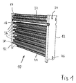
- the insert designated as a whole in FIG. 1 with the reference number 10 comprises two side walls 12, between which the various rollers described in greater detail below with reference to FIG. 2 extend. These rollers are mounted in openings and elongated holes, which are also described in more detail below with reference to FIG. 3.
- the insert 10 is otherwise in itself known manner introduced into a single tank, not shown, which is filled with a chemical liquid, the liquid level 50 is shown in Fig. 2.
- the insert 10 comprises, as shown in FIG. 2, an endless conveyor belt 22 with associated conveyor rollers 14, 16, 18 and 20. At least one of these conveyor rollers is provided with a drive in order to set the endless conveyor belt 22 in motion.
- the arrow A in FIG. 2 indicates the input side, on which the photographic material to be processed, seen from the left, is inserted between the two transport rollers 14 and 16 and then guided by means of the conveyor belt 22 through the individual tank to the output side indicated by the arrow B. becomes.
- the upper squeeze roller 26 is in the vertical direction freely movable in an elongated hole 13 which is arranged in the side wall 12. 2, the upper squeeze roller 26 is shown at a distance from the lower squeeze roller 28. In fact, due to its free movement, the upper squeeze roller 26 lies with its own weight on the film material, not shown, which is guided between the two squeeze rollers 26 and 28 on the exit side B to the next individual tank.
- This upper weight roller 32 is freely movable in the vertical direction in an elongated hole 34 of the side wall 12.
- a deflection belt 40 which is driven by drive rollers 38 and is deflected by a deflection roller 42 and a lower weight roller 44.
- the deflection belt 40 is expediently driven at the same speed at which the conveyor belt 22 is also driven.
- the deflection belt 40 presses up to the height of the drive roller 38 against the conveyor belt 22 or against the photographic material located therebetween, as a result of which reliable guidance is achieved in the region of the deflection of the photographic material or the conveyor belt 22.
- the lower weight roller 24 is freely movable in the vertical direction in an elongated hole 46 which is located in the side walls 12. Because of its own weight, the weight roller 44 exerts a downward force on the deflection belt 40, which is thereby automatically tensioned and held tight.
- displacement rollers 48 are provided in the center, which are mounted between the downward and upward parts of the conveyor belt.
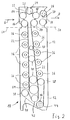
- the insert 10 also includes a plurality of floating rollers 36 which, as shown in FIG. 3, are mounted in oblique oblong holes in the side walls 12. Both on the area leading downward and on the area leading upward of the conveyor belt several floating rollers are arranged in a row. As the liquid level 50 shows, the floating rollers are below this level, that is to say in the chemical liquid of the associated individual tank. The chemical liquid causes a buoyancy force of the floating rollers 36 with the result that they press against the film material guided by the conveyor belt 22 with a certain pressure.
- the elongated holes 56 receiving the floating rollers 36 run in an oblique direction from bottom to top, namely in the direction of the conveyor belt. This direction is indicated in FIG. 3 by arrow C for the left row of elongated holes 56 and by arrow D for the right row of elongated holes 58.
- the floating rollers follow the oblique directions C and D, pressing against the conveyor belt 22 or the photographic material guided by this conveyor belt with a horizontal component.
- the pressure required in each case can be predetermined by the weight of the floating rollers 36.
- the illustration in Fig. 3 the bores 52, in which the transport rollers 14, 16, 18 and 20 are mounted, and the bore 44 for the lower squeeze roller 28.
- the bore 60 for the deflection roller 24 in the lower part of the side wall 12, the bore 60 for the deflection roller 24, the bores 62 for the mounting of the drive rollers 38 of the lower deflection belt 40 and the bore 64 for the deflection roller 42.
- the elongated hole 46 for the lower weight roller 44 which is freely movable in the vertical direction, can also be seen.
Landscapes
- Physics & Mathematics (AREA)
- General Physics & Mathematics (AREA)
- Photographic Processing Devices Using Wet Methods (AREA)
- Coating Apparatus (AREA)
- Spray Control Apparatus (AREA)
Applications Claiming Priority (2)
| Application Number | Priority Date | Filing Date | Title |
|---|---|---|---|
| JP300910/90 | 1990-11-05 | ||
| JP2300910A JPH04170542A (ja) | 1990-11-05 | 1990-11-05 | 連続現像装置用浸漬具 |
Publications (3)
| Publication Number | Publication Date |
|---|---|
| EP0484739A2 true EP0484739A2 (fr) | 1992-05-13 |
| EP0484739A3 EP0484739A3 (en) | 1993-01-20 |
| EP0484739B1 EP0484739B1 (fr) | 1997-05-28 |
Family
ID=17890602
Family Applications (1)
| Application Number | Title | Priority Date | Filing Date |
|---|---|---|---|
| EP91118037A Expired - Lifetime EP0484739B1 (fr) | 1990-11-05 | 1991-10-23 | Dispositif pour appareil de développement continu |
Country Status (5)
| Country | Link |
|---|---|
| US (1) | US5281989A (fr) |
| EP (1) | EP0484739B1 (fr) |
| JP (1) | JPH04170542A (fr) |
| DE (1) | DE59108721D1 (fr) |
| ES (1) | ES2104643T3 (fr) |
Families Citing this family (3)
| Publication number | Priority date | Publication date | Assignee | Title |
|---|---|---|---|---|
| US5506653A (en) * | 1993-04-14 | 1996-04-09 | Spillane; John D. | 58 second color print processor |
| JPH08339071A (ja) * | 1995-04-12 | 1996-12-24 | Noritsu Koki Co Ltd | 写真感光材料の搬送装置 |
| US6217238B1 (en) * | 1999-02-17 | 2001-04-17 | Phototrader, Inc. | Photographic film processor and method of developing film |
Family Cites Families (11)
| Publication number | Priority date | Publication date | Assignee | Title |
|---|---|---|---|---|
| US4140384A (en) * | 1974-07-11 | 1979-02-20 | Dainippon Screen Seizo Kabushiki Kaisha | Film conveyor |
| JPS5128034A (ja) * | 1974-08-30 | 1976-03-09 | Tomasu Supedeingu Oribaa | Gorufuaakunrenyosochi |
| JPS5233864U (fr) * | 1975-08-30 | 1977-03-10 | ||
| DE2548755C2 (de) * | 1975-10-31 | 1984-05-24 | Autopan Heimerdinger & Stäbler GmbH & Co, 7022 Leinfelden -Echterdingen | Fördereinrichtung für eine Vorrichtung zum Naßbehandeln von fotografischem Entwicklungsgut |
| DE2609463C3 (de) * | 1976-03-08 | 1981-02-19 | Ernst-Adolf 3250 Hameln Sitte | Einsatz für Durchlauf-Entwicklungs- |
| JPS5377523A (en) * | 1976-12-20 | 1978-07-10 | Tokyo Shiyutsupan Insatsu Kenk | Automatic developer on automatic photo printer |
| GB1579766A (en) * | 1977-05-30 | 1980-11-26 | Dainippon Screen Mfg | Film processing apparatus incorporating squeegee means |
| US4174901A (en) * | 1977-06-03 | 1979-11-20 | Dainippon Screen Seizo Kabushiki Kaisha | Film squeegee mechanism of automatic film developing apparatus |
| IL56538A (en) * | 1978-02-07 | 1981-05-20 | Grant Sidney | Apparatus for processing sheet material in a liquid bath |
| DE2951847A1 (de) * | 1979-12-21 | 1981-07-02 | Agfa-Gevaert Ag, 5090 Leverkusen | Vorrichtung zum entwickeln von fotografischen schichttraegern |
| JPS6242821A (ja) * | 1985-08-21 | 1987-02-24 | Toyoda Gosei Co Ltd | ゴム押出し成形品の製造方法 |
-
1990
- 1990-11-05 JP JP2300910A patent/JPH04170542A/ja active Pending
-
1991
- 1991-10-23 DE DE59108721T patent/DE59108721D1/de not_active Expired - Fee Related
- 1991-10-23 ES ES91118037T patent/ES2104643T3/es not_active Expired - Lifetime
- 1991-10-23 EP EP91118037A patent/EP0484739B1/fr not_active Expired - Lifetime
- 1991-10-29 US US07/784,557 patent/US5281989A/en not_active Expired - Fee Related
Also Published As
| Publication number | Publication date |
|---|---|
| JPH04170542A (ja) | 1992-06-18 |
| DE59108721D1 (de) | 1997-07-03 |
| EP0484739A3 (en) | 1993-01-20 |
| ES2104643T3 (es) | 1997-10-16 |
| EP0484739B1 (fr) | 1997-05-28 |
| US5281989A (en) | 1994-01-25 |
Similar Documents
| Publication | Publication Date | Title |
|---|---|---|
| DE60118948T2 (de) | Überführung von gegenständen zwischen entgegengesetzt angetriebenen förderern | |
| DE1961026B2 (de) | Entwicklungsvorrichtung fotografischer schichttraeger | |
| DE3150825C2 (de) | Vorrichtung zum Führen von Banknoten in einer Banknoten-Handhabungsmaschine | |
| DE3100799C2 (de) | Vorrichtung zum Eindicken von Schlamm | |
| DE102008044919A1 (de) | Vakuumbandförderer | |
| DE1897271U (de) | Foerdereinrichtung fuer blatt- und streifenfoermiges photomaterial in entwicklungsautomaten. | |
| DE1962837C3 (de) | Filmkassette für Selbstentwicklerkameras | |
| DE3209890C2 (de) | Beizanlage zum kontinuierlichen Beizen von Metallbändern | |
| EP0484739B1 (fr) | Dispositif pour appareil de développement continu | |
| DE19801823A1 (de) | Förderer für Stückgut | |
| DE69012389T2 (de) | Vorrichtung zum Ausrichten von Gegenständen mit unterschiedlichem Kopf- und Schaftdurchmesser in eine Richtung, wobei deren Köpfe in dieser oder gegen diese Richtung liegen. | |
| DE69130604T2 (de) | Aus Rollen bestehender Entwicklungstank | |
| DE3626412C2 (de) | Transporteinrichtung für belichtetes fotografisches Material | |
| DE69516439T2 (de) | Entwicklungsgerät | |
| DE3013049C2 (de) | Filmleiteinrichtung einer automatischen Filmentwicklungsvorrichtung | |
| DE19724034C2 (de) | Vorrichtung zum Behandeln von fotografischen Einzelblatt-Schichtträgern | |
| DE2609463C3 (de) | Einsatz für Durchlauf-Entwicklungs- | |
| DE9205053U1 (de) | Senkrechtförderer zum Fördern von Spinnhülsen | |
| DE69804905T2 (de) | Vorrichtung zur Transport-Richtungsänderung eines photoempfindlichen Materials in einer automatischen Entwicklungsvorrichtung | |
| DE68913197T2 (de) | Bandfuehrungsgeraet. | |
| EP0091065B1 (fr) | Dispositif de transport séparé dans un bain d'un appareil de développement par diffusion de deux feuilles pourvues de couches photosensibles | |
| DE69827339T2 (de) | Verarbeitung von fotografischem Material | |
| DE69406322T2 (de) | Auswringwalzen | |
| DE1522878C3 (de) | Behandlungsvorrichtung für photographisches Material | |
| DE2326887C3 (de) | Führungsvorrichtung für einen fotografischen Film oder dergleichen |
Legal Events
| Date | Code | Title | Description |
|---|---|---|---|
| PUAI | Public reference made under article 153(3) epc to a published international application that has entered the european phase |
Free format text: ORIGINAL CODE: 0009012 |
|
| AK | Designated contracting states |
Kind code of ref document: A2 Designated state(s): CH DE DK ES FR GB IT LI NL SE |
|
| PUAL | Search report despatched |
Free format text: ORIGINAL CODE: 0009013 |
|
| AK | Designated contracting states |
Kind code of ref document: A3 Designated state(s): CH DE DK ES FR GB IT LI NL SE |
|
| 17P | Request for examination filed |
Effective date: 19930713 |
|
| 17Q | First examination report despatched |
Effective date: 19940608 |
|
| GRAG | Despatch of communication of intention to grant |
Free format text: ORIGINAL CODE: EPIDOS AGRA |
|
| GRAH | Despatch of communication of intention to grant a patent |
Free format text: ORIGINAL CODE: EPIDOS IGRA |
|
| GRAH | Despatch of communication of intention to grant a patent |
Free format text: ORIGINAL CODE: EPIDOS IGRA |
|
| GRAA | (expected) grant |
Free format text: ORIGINAL CODE: 0009210 |
|
| AK | Designated contracting states |
Kind code of ref document: B1 Designated state(s): CH DE DK ES FR GB IT LI NL SE |
|
| PG25 | Lapsed in a contracting state [announced via postgrant information from national office to epo] |
Ref country code: IT Free format text: LAPSE BECAUSE OF FAILURE TO SUBMIT A TRANSLATION OF THE DESCRIPTION OR TO PAY THE FEE WITHIN THE PRE;WARNING: LAPSES OF ITALIAN PATENTS WITH EFFECTIVE DATE BEFORE 2007 MAY HAVE OCCURRED AT ANY TIME BEFORE 2007. THE CORRECT EFFECTIVE DATE MAY BE DIFFERENT FROM THE ONE RECORDED.SCRIBED TIME-LIMIT Effective date: 19970528 Ref country code: DK Effective date: 19970528 Ref country code: NL Free format text: LAPSE BECAUSE OF FAILURE TO SUBMIT A TRANSLATION OF THE DESCRIPTION OR TO PAY THE FEE WITHIN THE PRESCRIBED TIME-LIMIT Effective date: 19970528 |
|
| REG | Reference to a national code |
Ref country code: CH Ref legal event code: EP |
|
| REF | Corresponds to: |
Ref document number: 59108721 Country of ref document: DE Date of ref document: 19970703 |
|
| GBT | Gb: translation of ep patent filed (gb section 77(6)(a)/1977) |
Effective date: 19970715 |
|
| ET | Fr: translation filed | ||
| PG25 | Lapsed in a contracting state [announced via postgrant information from national office to epo] |
Ref country code: SE Effective date: 19970828 |
|
| REG | Reference to a national code |
Ref country code: ES Ref legal event code: FG2A Ref document number: 2104643 Country of ref document: ES Kind code of ref document: T3 |
|
| NLV1 | Nl: lapsed or annulled due to failure to fulfill the requirements of art. 29p and 29m of the patents act | ||
| PLBE | No opposition filed within time limit |
Free format text: ORIGINAL CODE: 0009261 |
|
| STAA | Information on the status of an ep patent application or granted ep patent |
Free format text: STATUS: NO OPPOSITION FILED WITHIN TIME LIMIT |
|
| 26N | No opposition filed | ||
| PGFP | Annual fee paid to national office [announced via postgrant information from national office to epo] |
Ref country code: GB Payment date: 19990930 Year of fee payment: 9 |
|
| PGFP | Annual fee paid to national office [announced via postgrant information from national office to epo] |
Ref country code: DE Payment date: 19991012 Year of fee payment: 9 |
|
| PGFP | Annual fee paid to national office [announced via postgrant information from national office to epo] |
Ref country code: ES Payment date: 19991014 Year of fee payment: 9 |
|
| PGFP | Annual fee paid to national office [announced via postgrant information from national office to epo] |
Ref country code: FR Payment date: 19991018 Year of fee payment: 9 |
|
| PGFP | Annual fee paid to national office [announced via postgrant information from national office to epo] |
Ref country code: CH Payment date: 19991021 Year of fee payment: 9 |
|
| PG25 | Lapsed in a contracting state [announced via postgrant information from national office to epo] |
Ref country code: GB Free format text: LAPSE BECAUSE OF NON-PAYMENT OF DUE FEES Effective date: 20001023 |
|
| PG25 | Lapsed in a contracting state [announced via postgrant information from national office to epo] |
Ref country code: ES Free format text: LAPSE BECAUSE OF NON-PAYMENT OF DUE FEES Effective date: 20001024 |
|
| PG25 | Lapsed in a contracting state [announced via postgrant information from national office to epo] |
Ref country code: CH Free format text: LAPSE BECAUSE OF NON-PAYMENT OF DUE FEES Effective date: 20001031 Ref country code: LI Free format text: LAPSE BECAUSE OF NON-PAYMENT OF DUE FEES Effective date: 20001031 |
|
| GBPC | Gb: european patent ceased through non-payment of renewal fee |
Effective date: 20001023 |
|
| REG | Reference to a national code |
Ref country code: CH Ref legal event code: PL |
|
| PG25 | Lapsed in a contracting state [announced via postgrant information from national office to epo] |
Ref country code: FR Free format text: LAPSE BECAUSE OF NON-PAYMENT OF DUE FEES Effective date: 20010629 |
|
| PG25 | Lapsed in a contracting state [announced via postgrant information from national office to epo] |
Ref country code: DE Free format text: LAPSE BECAUSE OF NON-PAYMENT OF DUE FEES Effective date: 20010703 |
|
| REG | Reference to a national code |
Ref country code: FR Ref legal event code: ST |
|
| REG | Reference to a national code |
Ref country code: ES Ref legal event code: FD2A Effective date: 20011113 |