EP0484757A2 - Method and apparatus for controlling power supply - Google Patents
Method and apparatus for controlling power supply Download PDFInfo
- Publication number
- EP0484757A2 EP0484757A2 EP91118187A EP91118187A EP0484757A2 EP 0484757 A2 EP0484757 A2 EP 0484757A2 EP 91118187 A EP91118187 A EP 91118187A EP 91118187 A EP91118187 A EP 91118187A EP 0484757 A2 EP0484757 A2 EP 0484757A2
- Authority
- EP
- European Patent Office
- Prior art keywords
- trickle charge
- battery
- voltage
- period
- adapter
- Prior art date
- Legal status (The legal status is an assumption and is not a legal conclusion. Google has not performed a legal analysis and makes no representation as to the accuracy of the status listed.)
- Granted
Links
Images


Classifications
-
- G—PHYSICS
- G06—COMPUTING OR CALCULATING; COUNTING
- G06F—ELECTRIC DIGITAL DATA PROCESSING
- G06F1/00—Details not covered by groups G06F3/00 - G06F13/00 and G06F21/00
- G06F1/26—Power supply means, e.g. regulation thereof
- G06F1/263—Arrangements for using multiple switchable power supplies, e.g. battery and AC
-
- H—ELECTRICITY
- H02—GENERATION; CONVERSION OR DISTRIBUTION OF ELECTRIC POWER
- H02J—ELECTRIC POWER NETWORKS; CIRCUIT ARRANGEMENTS OR SYSTEMS FOR SUPPLYING OR DISTRIBUTING ELECTRIC POWER; SYSTEMS FOR STORING ELECTRIC ENERGY
- H02J7/00—Circuit arrangements for charging or discharging batteries or for supplying loads from batteries
- H02J7/90—Regulation of charging or discharging current or voltage
- H02J7/96—Regulation of charging or discharging current or voltage in response to battery voltage
-
- G—PHYSICS
- G06—COMPUTING OR CALCULATING; COUNTING
- G06F—ELECTRIC DIGITAL DATA PROCESSING
- G06F1/00—Details not covered by groups G06F3/00 - G06F13/00 and G06F21/00
- G06F1/26—Power supply means, e.g. regulation thereof
- G06F1/28—Supervision thereof, e.g. detecting power-supply failure by out of limits supervision
-
- H—ELECTRICITY
- H02—GENERATION; CONVERSION OR DISTRIBUTION OF ELECTRIC POWER
- H02J—ELECTRIC POWER NETWORKS; CIRCUIT ARRANGEMENTS OR SYSTEMS FOR SUPPLYING OR DISTRIBUTING ELECTRIC POWER; SYSTEMS FOR STORING ELECTRIC ENERGY
- H02J7/00—Circuit arrangements for charging or discharging batteries or for supplying loads from batteries
- H02J7/865—Battery or charger load switching, e.g. concurrent charging and load supply
-
- Y—GENERAL TAGGING OF NEW TECHNOLOGICAL DEVELOPMENTS; GENERAL TAGGING OF CROSS-SECTIONAL TECHNOLOGIES SPANNING OVER SEVERAL SECTIONS OF THE IPC; TECHNICAL SUBJECTS COVERED BY FORMER USPC CROSS-REFERENCE ART COLLECTIONS [XRACs] AND DIGESTS
- Y10—TECHNICAL SUBJECTS COVERED BY FORMER USPC
- Y10S—TECHNICAL SUBJECTS COVERED BY FORMER USPC CROSS-REFERENCE ART COLLECTIONS [XRACs] AND DIGESTS
- Y10S320/00—Electricity: battery or capacitor charging or discharging
- Y10S320/11—Prioritized supply of power or power supply compensation
Definitions
- the present invention relates to a method and apparatus for controlling power supply.
- many electronic apparatuses such as lap-top personal computers or word processors, are operated by an AC adapter and/or an incorporated chargeable battery.
- the battery is charged, with a current (i.e., a charge current) supplied from the AC adapter. Even after the battery is in the full charge state, The battery charge is performed by supplying a trickle charge current, the amount of which is smaller than that of the normal charge current.
- This battery charge is generally referred to as "trickle charge.”
- a trickle charge current a fixed resistor having a constant resistance is used, and the trickle charge current is supplied through this resistor to the battery.
- the trickle charge current supplied to the battery is about 1/3 of the capacity of the battery. When the battery has a capacity of 2,100 mAh, the trickle charge current is about 70 mA.
- a diode for preventing back flow of a charge current and a fixed resistor for controlling a trickle charge current are arranged between an AC adapter and a battery, and the trickle charge is performed when the AC adapter is electrically connected to the electronic apparatus.
- the operating voltage of the electronic apparatus is high, it is likely that the battery will be in an over discharge state. Even then the battery voltage of the battery becomes 0V, the elements located around the trickle charge resistor must not be adversely affected by the heat which the resistor generates. Therefore, the wattage of the resistor has to be as large as possible.
- a resistor having a large wattage is inevitably large in size, and is not suitable for incorporation in an electronic apparatus which should be small in size and light in weight, like a lap-top type personal computer.
- an object of the present invention is to provide a method and apparatus for controlling power supply.
- a power supply controlling apparatus comprising: a battery being chargeable; supply means for supplying a trickle charge current to the battery; and control means for sampling voltages of the battery and the supply means at predetermined times during trickle charge of the battery and for causing the supply means to stop supply of the trickle charge current to the battery in accordance with a differential voltage value representing a difference between the sampled voltages.
- a power supply controlling method comprising the steps of: determining whether or not a battery is incorporated and whether or not an adapter for supplying a trickle charge current is connected, the battery being chargeable; starting trickle charge of the battery when the battery is incorporated and the adapter is connected; sampling voltages of the battery and the adapter at predetermined time during the trickle charge of the battery; and causing the adapter to stop supply of the trickle charge current to the battery in accordance with a differential voltage representing a difference between the sampled voltages.
- Fig. 1 shows a block diagram illustrating the configuration of a computer system used in one embodiment of the present invention.
- this computer system comprises a system bus 10, a main CPU (Central Processing Unit) 11 for controlling the entire system, a ROM (Read Only Memory) 12 for storing a control program inherent to the system, etc., a RAM (Random Access Memory) 13, a direct memory access controller (DMAC) 14 for performing the direct memory access control, a programmable interrupt controller (PIC) 15 settable by a program, a programmable interval timer (PIT) 16 settable by a program, a real time clock (RTC) 17 as a timer module with a drive battery 17a, an expansion RAM 18 with a large capacity and connectable to a special card slot, and a backup RAM 19 for storing backup data, etc. to implement a resume function.
- PIC programmable interrupt controller
- PIT programmable interval timer
- RTC real time clock
- the computer system also includes a floppy disk controller (FDC) 20.
- FDC floppy disk controller
- FDDs Floppy disk drives
- the computer system comprises a printer controller (PRT-CONT) 21, a universal asynchronous receiver/transmitter (UART) 22 as an input/output interface, a keyboard controller (KBC) 23, a display controller (DISP-CONT) 24, a video RAM (VRAM) 25, a power supply interface (PS-IF) 28, an AC adapter 29, a power supply circuit 30 having a power controller (PC-CPU) 50, a keyboard 36, an LCD (Liquid Crystal Display) 37, an expansion bus connector (EBC) 40, a hard disk drive interface (HDD-IF) 41, a hard disk drive (HDD) 42, a power supply switch 45, and a battery 48.
- PRT-CONT printer controller
- UART universal asynchronous receiver/transmitter
- KBC keyboard controller
- DISP-CONT display controller
- VRAM video RAM
- PS-IF power supply interface
- AC adapter 29, a power supply circuit 30 having a power controller (PC-CPU) 50, a keyboard 36, an LCD
- a printer 34 or the like is selectively connected to the printer controller 21.
- An RS-232C interface unit 35 is connected to the universal asynchronous receiver/transmitter 22 as needed.
- the keyboard controller 23 controls a key input through the keyboard 36.
- the display controller 24 controls the LCD 37 which is attached swingable to the computer body, or a CRT (Cathode Ray Tube) display 38 which is selectively connected to the computer.
- LCD 37 which is attached swingable to the computer body
- CRT Cathode Ray Tube
- the power supply interface 28 receives and transfers serial data from and to the power supply controller 50 in the power supply circuit 30.
- the AC adapter 29, connectable to the computer system is connected to an external power supply (not shown), and rectifies/smooths an AC voltage from the external power supply to output a DC voltage. If the AC adapter 29 is connected to the computer system to activate the system, the voltage is supplied from the AC adapter 29 through the power supply circuit 30 to each component of the computer system.
- a backup voltage V BK is supplied to each of the RAMs 13 and 18, the backup RAM 19 and the VRAM 25.
- the expansion bus connector 40 is used for functional expansion of the system.
- an external hard disk drive is selectively connected to the expansion bus connector 40.
- An expansion unit (not shown) having various components, such as a keyboard, a CRT display, a memory, a connector to the body of the computer system, can also be selectively connected to the expansion bus connector 40.
- the power supply switch 45 is used to activate this computer system, and has a momentary switch. When the DC voltage is not yet supplied to the individual components from the power supply circuit 30, or when the power supply is off, depression of the power supply switch 45 activates the power supply. When the DC voltage is supplied to the individual components from the power supply circuit 30 and the system is operated, or when the power supply is on, depression of the power supply switch 45 deactivates the power supply.
- the battery 48 can be recharged or rapidly charged and built in the computer system. If the AC adapter 29 is not connected to the computer system and the battery 48 is built therein instead, a DC voltage is supplied from the battery 48 through the power supply circuit 30 to the individual components of the computer system in order to activate the computer system.
- a nickel-hydrogen battery is used as the battery 48, for example.
- Fig. 2 is a graph showing the charging characteristic in the battery 48 being charged rapidly.
- the axis of ordinates represents the battery voltage of the battery 48
- the axis of abscissas represents the charge time of the battery 48.
- the battery 48 has such a charging characteristic as shown in Fig. 2. That is, the battery voltage per unit charge time greatly increases near the full charge state (battery voltage: approximately 18.5V, charge time: approximately 60 minutes).
- Fig. 3 is a structural block diagram illustrating the power supply circuit according to the embodiment of the prevent invention.
- the power supply circuit 30 includes the power supply controller 50, a DC/DC converter 60, voltage detectors 61 and 62, resistors 65 and 66, and FET switches 70, 71, 72 and 73.
- the AC adapter 29 has a constant-voltage output terminal 29a, a control-signal input terminal 29b, and a constant-current output terminal 29c.
- a constant voltage of 18V is output from the constant-voltage output terminal 29a.
- a constant current of 2.2A is output from the constant-current output terminal 29c.
- a control signal from the power supply controller 50 is supplied to the control signal input terminal 29b. In response to the control signal, the AC adapter 29 outputs either the constant voltage or constant current.
- the DC/DC converter 60 generates a DC voltage of a predetermined level based on the DC voltage supplied from either the AC adapter 29 or the battery 48, and supplies the generated DC voltage of the predetermined level to the individual components of the computer system. Since the DC voltage from the AC adapter 29 or the battery 48 is 18V, DC voltages of +5V, +12V and -9V are actually supplied to predetermined components.
- the voltage detector 61 detects an adapter voltage of the AC adapter 29, i.e., the constant voltage output from the constant-voltage output terminal 29a.
- the voltage detector 62 detects the battery voltage of the battery 48. Based on these detected voltages, it is determined whether the AC adapter 29 or the battery 48 is connected to the computer system.
- the FET switch 70 is used to supply or stop supplying the DC voltage to the DC/DC converter 60 from the AC adapter 29 or the battery 48. When the FET switch 70 is on, the DC voltage is supplied to the DC/DC converter 60. Therefore, the DC/DC converter 60 can supply the above-described voltage of the predetermined level to each component.
- the FET switch 71 is used to supply the DC voltage from the battery 48 through the FET switch 70 to the DC/DC converter 60. When the FET switch 71 is turned on, the DC voltage can be supplied to the DC/DC converter 60 from the battery 48.
- the FET switch 72 is utilized to supply the constant current from the constant-current output terminal 29c of the AC adapter 29 to the battery 48. When the FET switch 72 is on, the constant current is supplied to the battery 48 for rapid charge.
- the FET switch 73 is used to supply the constant voltage from the constant-voltage output terminal 29a of the Ac adapter 29 to the battery 48. When the FET switch 73 is on, the constant voltage is supplied to the battery 48 through the resistor 66 for trickle charge.
- the trickle charge represents that a rechargeable battery, even after fully charged by an AC adapter, continues to be charged all the time with a current smaller than a charge current.
- the resistor 65 as a current limiting resistor, used to inhibit supplying of a large current to the battery 48, has usually a high resistance.
- the resistor 66 used for trickle charge, has usually a low resistance, for example, several tens ⁇ .
- the power supply controller 50 has a CPU 51, a RAM 52, a ROM 53, a timer 54, an output port 55, an A/D converter 56 and an input port 57.
- the CPU 51 constituted by one chip, controls a voltage supply to the individual component, and rapid charge/trickle charge to the battery 48.
- the trickle charge is executed.
- the ROM 53 stores control programs, etc. to be used for the voltage supply control and the rapid charge/trickle charge control.
- the RAM 52 is used as the main memory of the CPU 51. Assigned to the RAM 52 are various memory areas, as a flag, a counter and the like, used to the voltage supply control and the rapid charge/trickle charge control. In this embodiment, part of RAM 52 is used as a duty register, a timer interruption flag, and a counter, as described later.
- the timer 54 outputs a timer value to the CPU 51 by a predetermined cycle.
- the timer value is utilized for executing the trickle charge control every a predetermined time, e.g., 65 ms.
- the output port 55 outputs a control signal individually to the control-signal input terminal 29b of the AC adapter 29, and the FET switches 70, 71, 72 and 73, and transmits data to the power supply interface 28.
- the AC adapter 29 In response to the control signal at the control-signal input terminal 29b, the AC adapter 29 outputs the constant current or the constant voltage.
- the FET switches 70, 71, 72 and 73 are turned on or off depending on the received control signals at each FET switch.
- a control signal used to turn on/off the FET switch 72 is output from the output port 55.
- the A/D converter 56 converts analog voltages output respectively from the voltage detectors 61 and 62 into digital voltages.
- the input port 57 receives a signal indicating whether the power supply switch 45 is depressed. As shown in Fig. 3, the level of a voltage to the input port 57 is Vcc as long as the power supply switch 45 is not depressed. Since the power supply switch 45 is a momentary switch as described above, however, the level of the received voltage at the input port 57 is "0" during a predetermined period of time upon each depression of the power supply switch 45. By detecting a change in voltage level, therefore, it can be determined whether the power supply switch 45 is depressed.
- Fig. 3 is a graph explaining a change of a trickle charge current during the trickle charge according to the present invention and during the trickle charge according to the conventional case.
- the axis of ordinates represents a differential voltage representing a difference between the voltage of the AC adapter 29 and the battery voltage of the battery 48
- the axis of abscissas represents a trickle charge current.
- Symbol "It” denotes a desirable trickle charge current value
- symbol “Vd” denotes a differential voltage (about 3V) in a normal operating state
- the "1W, 2W, " denote the wattage of the trickle charge resistor.
- FIG. 3 is a value necessary to prevent the elements located around the resistor from being adversely affected by heat produced during the trickle charge current flows into the resistor.
- the trickle charge resistor must have a wattage equal to or larger than 2W. If the resistor has a wattage smaller than 2W, the elements located around the resistor will be adversely affected by the heat produced in the resistor.
- linear line B including solid and broken lines represents a change of the trickle charge current during the trickle charge according to the conventional case
- bent line A as a solid line) represents a change of the trickle charge current during the trickle charge according to the present invention.
- Figs. 4A and 4B are flowcharts showing the trickle charge control performed by the CPU 51 of the power source controller 50
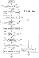
- Fig. 5 is a flowchart showing the timer interruption processing executed by the CPU 51.
- the CPU 51 of the power supply controller 50 executes the trickle charge control program stored in ROM 53.
- the timer interruption processing is performed by the timer interruption cycle set by the execution of the trickle charge control program.
- a timer interrupt flag indicates whether or not the trickle charge control is executed. As will be described later, the timer interruption processing is executed every the predetermined time of 65 ms, and the timer interrupt flag is set to be "1" in each timer interruption processing. In other words, the trickle charge control is executed every 65 ms.
- a count value corresponding to a content of memory area in the RAM 52 assigned as a counter is referred to.
- the count value of the counter is one of “0,” “1,” “2” and “3.”
- the count value is repeatedly counted up in the order of "0,” “1,” “2” and “3.”
- the count value is incremented by 1 every 65 ms. Therefore, an execution period of the trickle charge is set every a period of 260 ms (65 ms ⁇ 4).
- a duty register is a 4 bit register representing an execution period of the trickle charge every the period of 260 ms.
- the register value (in a hexadecimal number) of the duty register is "0" (corresponding to "0000” in a binary number)
- no trickle charge is executed during the period of 260 ms.
- the register value of the duty register is "1" (corresponding to "0001" in a binary number)
- the trickle charge is executed for about 65 ms from the start of the period of 260 ms.
- the trickle charge is executed for about 130 ms (65 ms ⁇ 2) from the start of the period of 260 ms.
- the register value of the duty register is "F” (corresponding to "1111” in a binary number)
- the trickle charge is executed during the period of 260 ms.
- step S1 it is determined whether or not the FET switch 70 is on, i.e., whether or not a voltage is supplied to each component of the computer system by either the AD adapter 29 or the battery 48. If the FET switch 70 is on, the timer interrupt cycle is set to be 65 ms, for example, in step S2. Further, in step S3, the count value of the counter is set to be "0.”
- step S4 it is determined whether or not the timer interrupt flag is "1." Since the timer interrupt cycle is set to be 65 ms in step S2, the timer interruption processing shown in Fig. 5 is executed every the period of 65 ms. In the timer interruption processing, the timer interrupt flag is set to be "1" in step F1. Therefore, the processing step S4 and sequent steps are not carried out until the processing of step F1 is executed.
- step S4 if the timer interrupt flag is "1," the timer interrupt flag is set to be “0” in step S5. In subsequent step S6, it is determined whether or not the count value of the counter is "0.”
- step S6 if the count value of the counter is "0," it is determined that the present time corresponds to the start time of the period of 260 ms. Hence, processes of steps 7-16 are executed so as to set the execution period of the trickle charge.
- step S7 it is determined whether or not the AC adapter 29 is connected to the computer system.
- step S8 it is determined whether or not the battery 48 is incorporated in the computer system.
- step S9 the duty register value of the duty register is set to be "0" (step S9). That is, the trickle charge is not performed.
- step S10 an adapter voltage value representing the adapter voltage of the AC adapter 29 output from the voltage detector 61 to the A/D converter 56 is read.
- step S11 a battery voltage value representing the battery voltage of the battery 48 output from the voltage detector 62 to the A/D converter 56 is read.
- step S12 a differential voltage value representing a difference between the adapter voltage value and the battery voltage value (adapter voltage value - battery voltage value) is compared with a reference voltage value of e.g., 6V.
- a reference voltage value of 6V corresponds to the upper limit value of the trickle charge resistor which a wattage is 1.
- step S12 If the differential voltage value is equal to or smaller than 6V in step S12, the duty register value is set to be "F,” i.e., "1111" in step S13. This represents that the trickle charge is executed during the period of 260 ms.
- step S14 If the differential voltage value is larger than 6V in step S12, it is determined whether or not the differential voltage value is larger than 9V (step S14). If the differential voltage value is equal to or smaller than 9V in step S14, the duty register value is set to be "3," i.e., "0011" in step S15. If, on the other hand, the differential voltage value is larger than 9V in step S14, the duty register value is set to be "1," i.e., "0001" in step S16.
- step S17 If the count value is not "0" in step S6 or if the processing of steps S9, S13, S15 or S16 has completed, then processing of step S17 is executed.
- step S17 it is determined whether or not the least significant bit (LSB) of the duty register is "1.” If the least significant bit is "1" in step S17, a control signal to execute the trickle charge is produced in step S19.
- the control signal used for turning on the FET switch 73 is output from the output port 55 to the FET switch 73. Accordingly, a trickle charge current is supplied from the AC adapter 29 to the battery 48 through the trickle charge resistor 66, thus starting the trickle charge.
- step S17 If the least significant bit of the duty register is not "1" but “0" in step S17, a control signal to stop the trickle charge is produced in step S18.
- the control signal for turning off the FET switch 73 is supplied from the output port 55 to the FET switch 73. Accordingly, the AC adapter 29 is prevented from supplying the trickle charge current to the battery 48, thus stopping the trickle charge.
- step S20 one bit rotation is executed for the duty register, so that the duty register value of the duty register is rotated to the right by one bit.
- step S21 the count value of the counter is incremented by 1. As mentioned above, the count value is repeatedly counted up in the order of "0,” “1,” "2” and “3.” Therefore, if the counter value is "3,” it is set to be "0" in step S21. Thereafter, the processing flow returns to step S3, so that the trickle charge control mentioned above is performed every period of 65 ms.
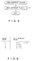
- Fig. 6 shows the case where a hexadecimal number of "3" (i.e., "0011") is set as the duty register value. It should be noted that the count value is incremented by 1 every the period of 65 ms.
- step S17 when the count value of the counter is "0,” it is determined in step S17 that the least significant bit of the duty register is “1.” Therefore, the trickle charge is continued (step S19).
- step S20 the duty register value "0011” is changed to "1001” by one bit rotation to the right, and in step S21, the count value "0" is incremented by 1, thereby to obtain "1.”
- step S17 After 65 ms elapses, the count value of the counter is "1," it is determined in step S17 that the least significant bit of the duty register is “1.” In this case, the trickle charge is continued (step S19). The duty register value "1001” is changed to “1100” by one bit rotation to the right, and the count value "1” is incremented by 1, thereby to obtain "2.”
- step S17 After further 65 ms elapses (i.e., after 130 ms elapses from the start of the trickle charge control), the count value of the counter is "2," it is determined in step S17 that the least significant bit of the duty register is "0.” In this case, the trickle charge is stopped (step S18).
- the duty register value "1100” is changed to "0110” by one bit rotation to the right, and the count value "2" is incremented by 1, thereby to obtain "3.”
- step S17 After further 65 ms elapses (i.e., after 195 ms elapses from the start of the trickle charge control), the count value of the counter is "3," it is determined in step S17 that the least significant bit of the duty register is "0". In this case, stopping of the trickle charge is continued (step S18).
- the duty register value "0110” is changed to "0011” by one bit rotation to the right, and the count value "3" is changed to "0” by increment of the count value.
- step S6 After further 65 ms elapses (i.e., after 260 ms elapses from the start of the trickle charge control), it is determined in step S6 that the count value of the counter is "0.” Therefore, steps S7-S16 are executed, wherein a new duty register value is set in the register and the trickle charge control is executed in accordance with the new duty register value.
- trickle charge is started or stopped at the predetermined timings based on a differential voltage. Even when the differential voltage increases, a trickle charge current is close to the desirable value "It" at all times, as is indicated by the bent line A in Fig. 3. Since the wattage of the trickle charge resistor 66 need not be large (1W in the case of the present embodiment), the resistor 66 of a small size can be used.
- the trickle charge is started or stopped at intervals set on the basis of the differential voltage representing the difference between the adapter voltage and the battery voltage.
- the trickle charge can be started or stopped either in multi-steps or linearly on the basis of the differential voltage.
Landscapes
- Engineering & Computer Science (AREA)
- Power Engineering (AREA)
- Theoretical Computer Science (AREA)
- Physics & Mathematics (AREA)
- General Engineering & Computer Science (AREA)
- General Physics & Mathematics (AREA)
- Charge And Discharge Circuits For Batteries Or The Like (AREA)
- Power Sources (AREA)
Abstract
Description
- The present invention relates to a method and apparatus for controlling power supply.
- In general, many electronic apparatuses, such as lap-top personal computers or word processors, are operated by an AC adapter and/or an incorporated chargeable battery. The battery is charged, with a current (i.e., a charge current) supplied from the AC adapter. Even after the battery is in the full charge state, The battery charge is performed by supplying a trickle charge current, the amount of which is smaller than that of the normal charge current. This battery charge is generally referred to as "trickle charge." For the trickle charge, a fixed resistor having a constant resistance is used, and the trickle charge current is supplied through this resistor to the battery. In general, the trickle charge current supplied to the battery is about 1/3 of the capacity of the battery. When the battery has a capacity of 2,100 mAh, the trickle charge current is about 70 mA.
- In this type of electronic apparatus, a diode for preventing back flow of a charge current and a fixed resistor for controlling a trickle charge current are arranged between an AC adapter and a battery, and the trickle charge is performed when the AC adapter is electrically connected to the electronic apparatus. In the case where the operating voltage of the electronic apparatus is high, it is likely that the battery will be in an over discharge state. Even then the battery voltage of the battery becomes 0V, the elements located around the trickle charge resistor must not be adversely affected by the heat which the resistor generates. Therefore, the wattage of the resistor has to be as large as possible. However, a resistor having a large wattage is inevitably large in size, and is not suitable for incorporation in an electronic apparatus which should be small in size and light in weight, like a lap-top type personal computer.
- Under the circumstances mentioned above, there is a demand for a power source control apparatus which controls a trickle charge current such that the trickle charge can be efficiently performed by use of a small-sized and small-wattage resistor element.
- Accordingly, an object of the present invention is to provide a method and apparatus for controlling power supply.
- According to one aspect of the present invention, there is provided a power supply controlling apparatus comprising: a battery being chargeable; supply means for supplying a trickle charge current to the battery; and control means for sampling voltages of the battery and the supply means at predetermined times during trickle charge of the battery and for causing the supply means to stop supply of the trickle charge current to the battery in accordance with a differential voltage value representing a difference between the sampled voltages.
- According to another aspect of the present invention, there is provided a power supply controlling method comprising the steps of: determining whether or not a battery is incorporated and whether or not an adapter for supplying a trickle charge current is connected, the battery being chargeable; starting trickle charge of the battery when the battery is incorporated and the adapter is connected; sampling voltages of the battery and the adapter at predetermined time during the trickle charge of the battery; and causing the adapter to stop supply of the trickle charge current to the battery in accordance with a differential voltage representing a difference between the sampled voltages.
- This invention can be more fully understood from the following detailed description when taken in conjunction with the accompanying drawings, in which:
- Fig. 1 is a block circuit diagram showing a computer system used in an embodiment of the present invention;
- Fig. 2 is a block circuit diagram showing a power source circuit used in the embodiment of the present invention;
- Fig. 3 is a graph explaining a change of a trickle charge current during the trickle charge according to the present invention and during the trickle charge according to the conventional case;
- Figs. 4A and 4B are flowcharts of the trickle charge control in a CPU of a power source controller according to the embodiment;
- Fig. 5 is a flowchart of timer interrupt processing in the CPU of the power source controller according to the embodiment; and
- Fig. 6 is a diagram explaining a change of a count value and a duty register value during the trickle charge control.
- A preferred embodiment of the present invention will now be described referring to the accompanying drawings.
- Fig. 1 shows a block diagram illustrating the configuration of a computer system used in one embodiment of the present invention. As shown in Fig. 1, this computer system comprises a
system bus 10, a main CPU (Central Processing Unit) 11 for controlling the entire system, a ROM (Read Only Memory) 12 for storing a control program inherent to the system, etc., a RAM (Random Access Memory) 13, a direct memory access controller (DMAC) 14 for performing the direct memory access control, a programmable interrupt controller (PIC) 15 settable by a program, a programmable interval timer (PIT) 16 settable by a program, a real time clock (RTC) 17 as a timer module with a drive battery 17a, anexpansion RAM 18 with a large capacity and connectable to a special card slot, and abackup RAM 19 for storing backup data, etc. to implement a resume function. - The computer system also includes a floppy disk controller (FDC) 20. Floppy disk drives (FDDs) 32 and 33 are connected to the
floppy disk controller 20 which controls these disk drives. - Further, the computer system comprises a printer controller (PRT-CONT) 21, a universal asynchronous receiver/transmitter (UART) 22 as an input/output interface, a keyboard controller (KBC) 23, a display controller (DISP-CONT) 24, a video RAM (VRAM) 25, a power supply interface (PS-IF) 28, an
AC adapter 29, apower supply circuit 30 having a power controller (PC-CPU) 50, akeyboard 36, an LCD (Liquid Crystal Display) 37, an expansion bus connector (EBC) 40, a hard disk drive interface (HDD-IF) 41, a hard disk drive (HDD) 42, apower supply switch 45, and abattery 48. - A
printer 34 or the like is selectively connected to theprinter controller 21. An RS-232C interface unit 35 is connected to the universal asynchronous receiver/transmitter 22 as needed. Thekeyboard controller 23 controls a key input through thekeyboard 36. - The
display controller 24 controls theLCD 37 which is attached swingable to the computer body, or a CRT (Cathode Ray Tube)display 38 which is selectively connected to the computer. - The
power supply interface 28 receives and transfers serial data from and to thepower supply controller 50 in thepower supply circuit 30. - The
AC adapter 29, connectable to the computer system, is connected to an external power supply (not shown), and rectifies/smooths an AC voltage from the external power supply to output a DC voltage. If theAC adapter 29 is connected to the computer system to activate the system, the voltage is supplied from theAC adapter 29 through thepower supply circuit 30 to each component of the computer system. - A backup voltage VBK is supplied to each of the
RAMs backup RAM 19 and theVRAM 25. - The
expansion bus connector 40 is used for functional expansion of the system. For example, an external hard disk drive is selectively connected to theexpansion bus connector 40. An expansion unit (not shown) having various components, such as a keyboard, a CRT display, a memory, a connector to the body of the computer system, can also be selectively connected to theexpansion bus connector 40. - The
power supply switch 45 is used to activate this computer system, and has a momentary switch. When the DC voltage is not yet supplied to the individual components from thepower supply circuit 30, or when the power supply is off, depression of thepower supply switch 45 activates the power supply. When the DC voltage is supplied to the individual components from thepower supply circuit 30 and the system is operated, or when the power supply is on, depression of thepower supply switch 45 deactivates the power supply. - The
battery 48 can be recharged or rapidly charged and built in the computer system. If theAC adapter 29 is not connected to the computer system and thebattery 48 is built therein instead, a DC voltage is supplied from thebattery 48 through thepower supply circuit 30 to the individual components of the computer system in order to activate the computer system. A nickel-hydrogen battery is used as thebattery 48, for example. - Fig. 2 is a graph showing the charging characteristic in the
battery 48 being charged rapidly. In Fig. 2, the axis of ordinates represents the battery voltage of thebattery 48, the axis of abscissas represents the charge time of thebattery 48. Thebattery 48 has such a charging characteristic as shown in Fig. 2. That is, the battery voltage per unit charge time greatly increases near the full charge state (battery voltage: approximately 18.5V, charge time: approximately 60 minutes). - The
power supply circuit 30 will now be described. Fig. 3 is a structural block diagram illustrating the power supply circuit according to the embodiment of the prevent invention. Thepower supply circuit 30 includes thepower supply controller 50, a DC/DC converter 60,voltage detectors resistors FET switches - The
AC adapter 29 has a constant-voltage output terminal 29a, a control-signal input terminal 29b, and a constant-current output terminal 29c. A constant voltage of 18V is output from the constant-voltage output terminal 29a. A constant current of 2.2A is output from the constant-current output terminal 29c. A control signal from thepower supply controller 50 is supplied to the control signal input terminal 29b. In response to the control signal, the AC adapter 29 outputs either the constant voltage or constant current. - The DC/
DC converter 60 generates a DC voltage of a predetermined level based on the DC voltage supplied from either theAC adapter 29 or thebattery 48, and supplies the generated DC voltage of the predetermined level to the individual components of the computer system. Since the DC voltage from theAC adapter 29 or thebattery 48 is 18V, DC voltages of +5V, +12V and -9V are actually supplied to predetermined components. - The
voltage detector 61 detects an adapter voltage of theAC adapter 29, i.e., the constant voltage output from the constant-voltage output terminal 29a. Thevoltage detector 62 detects the battery voltage of thebattery 48. Based on these detected voltages, it is determined whether theAC adapter 29 or thebattery 48 is connected to the computer system. - The
FET switch 70 is used to supply or stop supplying the DC voltage to the DC/DC converter 60 from theAC adapter 29 or thebattery 48. When theFET switch 70 is on, the DC voltage is supplied to the DC/DC converter 60. Therefore, the DC/DC converter 60 can supply the above-described voltage of the predetermined level to each component. - The
FET switch 71 is used to supply the DC voltage from thebattery 48 through theFET switch 70 to the DC/DC converter 60. When theFET switch 71 is turned on, the DC voltage can be supplied to the DC/DC converter 60 from thebattery 48. - The
FET switch 72 is utilized to supply the constant current from the constant-current output terminal 29c of theAC adapter 29 to thebattery 48. When theFET switch 72 is on, the constant current is supplied to thebattery 48 for rapid charge. - The
FET switch 73 is used to supply the constant voltage from the constant-voltage output terminal 29a of theAc adapter 29 to thebattery 48. When theFET switch 73 is on, the constant voltage is supplied to thebattery 48 through theresistor 66 for trickle charge. - The trickle charge represents that a rechargeable battery, even after fully charged by an AC adapter, continues to be charged all the time with a current smaller than a charge current.
- The
resistor 65 as a current limiting resistor, used to inhibit supplying of a large current to thebattery 48, has usually a high resistance. - The
resistor 66, used for trickle charge, has usually a low resistance, for example, several tens Ω. - The
power supply controller 50 has aCPU 51, aRAM 52, aROM 53, atimer 54, anoutput port 55, an A/D converter 56 and an input port 57. - The
CPU 51, constituted by one chip, controls a voltage supply to the individual component, and rapid charge/trickle charge to thebattery 48. In the present invention, the trickle charge is executed. - The
ROM 53 stores control programs, etc. to be used for the voltage supply control and the rapid charge/trickle charge control. - The
RAM 52 is used as the main memory of theCPU 51. Assigned to theRAM 52 are various memory areas, as a flag, a counter and the like, used to the voltage supply control and the rapid charge/trickle charge control. In this embodiment, part ofRAM 52 is used as a duty register, a timer interruption flag, and a counter, as described later. - The
timer 54 outputs a timer value to theCPU 51 by a predetermined cycle. In the embodiment, the timer value is utilized for executing the trickle charge control every a predetermined time, e.g., 65 ms. - The
output port 55 outputs a control signal individually to the control-signal input terminal 29b of theAC adapter 29, and the FET switches 70, 71, 72 and 73, and transmits data to thepower supply interface 28. In response to the control signal at the control-signal input terminal 29b, theAC adapter 29 outputs the constant current or the constant voltage. The FET switches 70, 71, 72 and 73 are turned on or off depending on the received control signals at each FET switch. To control the charging of thebattery 48, a control signal used to turn on/off theFET switch 72 is output from theoutput port 55. - The A/
D converter 56 converts analog voltages output respectively from thevoltage detectors - The input port 57 receives a signal indicating whether the
power supply switch 45 is depressed. As shown in Fig. 3, the level of a voltage to the input port 57 is Vcc as long as thepower supply switch 45 is not depressed. Since thepower supply switch 45 is a momentary switch as described above, however, the level of the received voltage at the input port 57 is "0" during a predetermined period of time upon each depression of thepower supply switch 45. By detecting a change in voltage level, therefore, it can be determined whether thepower supply switch 45 is depressed. - A description will now be given, with reference to the flowcharts shown in Fig. 3, Figs. 4A and 4B and Fig. 5, in the trickle charge control for the
battery 48 in theCPU 51 of thepower supply controller 50. - Fig. 3 is a graph explaining a change of a trickle charge current during the trickle charge according to the present invention and during the trickle charge according to the conventional case. In Fig. 3, the axis of ordinates represents a differential voltage representing a difference between the voltage of the
AC adapter 29 and the battery voltage of thebattery 48, and the axis of abscissas represents a trickle charge current. Symbol "It" denotes a desirable trickle charge current value, symbol "Vd" denotes a differential voltage (about 3V) in a normal operating state, and the "1W, 2W, ..." denote the wattage of the trickle charge resistor. The wattage indicated in Fig. 3 is a value necessary to prevent the elements located around the resistor from being adversely affected by heat produced during the trickle charge current flows into the resistor. For example, when the trickle charge current is 200 mA, the trickle charge resistor must have a wattage equal to or larger than 2W. If the resistor has a wattage smaller than 2W, the elements located around the resistor will be adversely affected by the heat produced in the resistor. In Fig. 3, linear line B including solid and broken lines represents a change of the trickle charge current during the trickle charge according to the conventional case, and bent line A as a solid line) represents a change of the trickle charge current during the trickle charge according to the present invention. - Figs. 4A and 4B are flowcharts showing the trickle charge control performed by the
CPU 51 of thepower source controller 50, and Fig. 5 is a flowchart showing the timer interruption processing executed by theCPU 51. - The
CPU 51 of thepower supply controller 50 executes the trickle charge control program stored inROM 53. The timer interruption processing is performed by the timer interruption cycle set by the execution of the trickle charge control program. - In the trickle charge control, contents of a memory area in the
RAM 52 assigned as a flag area are referred to. A timer interrupt flag indicates whether or not the trickle charge control is executed. As will be described later, the timer interruption processing is executed every the predetermined time of 65 ms, and the timer interrupt flag is set to be "1" in each timer interruption processing. In other words, the trickle charge control is executed every 65 ms. - Also, a count value corresponding to a content of memory area in the
RAM 52 assigned as a counter is referred to. The count value of the counter is one of "0," "1," "2" and "3." The count value is repeatedly counted up in the order of "0," "1," "2" and "3." The count value is incremented by 1 every 65 ms. Therefore, an execution period of the trickle charge is set every a period of 260 ms (65 ms × 4). - Further, contents of a memory area in
RAM 52 assigned as the register are referred to. A duty register is a 4 bit register representing an execution period of the trickle charge every the period of 260 ms. When the register value (in a hexadecimal number) of the duty register is "0" (corresponding to "0000" in a binary number), no trickle charge is executed during the period of 260 ms. When the register value of the duty register is "1" (corresponding to "0001" in a binary number), the trickle charge is executed for about 65 ms from the start of the period of 260 ms. When the register value of the duty register is "3" (corresponding to "0011" in a binary number), the trickle charge is executed for about 130 ms (65 ms × 2) from the start of the period of 260 ms. When the register value of the duty register is "F" (corresponding to "1111" in a binary number), the trickle charge is executed during the period of 260 ms. - In step S1, it is determined whether or not the
FET switch 70 is on, i.e., whether or not a voltage is supplied to each component of the computer system by either theAD adapter 29 or thebattery 48. If theFET switch 70 is on, the timer interrupt cycle is set to be 65 ms, for example, in step S2. Further, in step S3, the count value of the counter is set to be "0." - In step S4, it is determined whether or not the timer interrupt flag is "1." Since the timer interrupt cycle is set to be 65 ms in step S2, the timer interruption processing shown in Fig. 5 is executed every the period of 65 ms. In the timer interruption processing, the timer interrupt flag is set to be "1" in step F1. Therefore, the processing step S4 and sequent steps are not carried out until the processing of step F1 is executed.
- In step S4, if the timer interrupt flag is "1," the timer interrupt flag is set to be "0" in step S5. In subsequent step S6, it is determined whether or not the count value of the counter is "0."
- In step S6, if the count value of the counter is "0," it is determined that the present time corresponds to the start time of the period of 260 ms. Hence, processes of steps 7-16 are executed so as to set the execution period of the trickle charge.
- In step S7, it is determined whether or not the
AC adapter 29 is connected to the computer system. In step S8, it is determined whether or not thebattery 48 is incorporated in the computer system. - If the
AC adapter 29 is not connected to the computer system in step S7 or if thebattery 48 is not incorporated in the computer system in step S8, the duty register value of the duty register is set to be "0" (step S9). That is, the trickle charge is not performed. - If the
AC adapter 29 is connected to the computer system and thebattery 48 is incorporated therein, it is determined that trickle charge can be started. In step S10, an adapter voltage value representing the adapter voltage of theAC adapter 29 output from thevoltage detector 61 to the A/D converter 56 is read. In step S11, a battery voltage value representing the battery voltage of thebattery 48 output from thevoltage detector 62 to the A/D converter 56 is read. - In step S12, a differential voltage value representing a difference between the adapter voltage value and the battery voltage value (adapter voltage value - battery voltage value) is compared with a reference voltage value of e.g., 6V. As is seen from Fig. 3, the reference voltage value of 6V corresponds to the upper limit value of the trickle charge resistor which a wattage is 1.
- If the differential voltage value is equal to or smaller than 6V in step S12, the duty register value is set to be "F," i.e., "1111" in step S13. This represents that the trickle charge is executed during the period of 260 ms.
- If the differential voltage value is larger than 6V in step S12, it is determined whether or not the differential voltage value is larger than 9V (step S14). If the differential voltage value is equal to or smaller than 9V in step S14, the duty register value is set to be "3," i.e., "0011" in step S15. If, on the other hand, the differential voltage value is larger than 9V in step S14, the duty register value is set to be "1," i.e., "0001" in step S16.
- If the count value is not "0" in step S6 or if the processing of steps S9, S13, S15 or S16 has completed, then processing of step S17 is executed.
- In step S17, it is determined whether or not the least significant bit (LSB) of the duty register is "1." If the least significant bit is "1" in step S17, a control signal to execute the trickle charge is produced in step S19. The control signal used for turning on the
FET switch 73 is output from theoutput port 55 to theFET switch 73. Accordingly, a trickle charge current is supplied from theAC adapter 29 to thebattery 48 through thetrickle charge resistor 66, thus starting the trickle charge. - If the least significant bit of the duty register is not "1" but "0" in step S17, a control signal to stop the trickle charge is produced in step S18. The control signal for turning off the
FET switch 73 is supplied from theoutput port 55 to theFET switch 73. Accordingly, theAC adapter 29 is prevented from supplying the trickle charge current to thebattery 48, thus stopping the trickle charge. - In step S20, one bit rotation is executed for the duty register, so that the duty register value of the duty register is rotated to the right by one bit.
- In step S21, the count value of the counter is incremented by 1. As mentioned above, the count value is repeatedly counted up in the order of "0," "1," "2" and "3." Therefore, if the counter value is "3," it is set to be "0" in step S21. Thereafter, the processing flow returns to step S3, so that the trickle charge control mentioned above is performed every period of 65 ms.
- A description will now be given, with reference to Fig. 6, in changes of a count value and a duty register value during the trickle charge control. Fig. 6 shows the case where a hexadecimal number of "3" (i.e., "0011") is set as the duty register value. It should be noted that the count value is incremented by 1 every the period of 65 ms.
- As may be understood from Fig. 6, when the count value of the counter is "0," it is determined in step S17 that the least significant bit of the duty register is "1." Therefore, the trickle charge is continued (step S19). In step S20, the duty register value "0011" is changed to "1001" by one bit rotation to the right, and in step S21, the count value "0" is incremented by 1, thereby to obtain "1."
- After 65 ms elapses, the count value of the counter is "1," it is determined in step S17 that the least significant bit of the duty register is "1." In this case, the trickle charge is continued (step S19). The duty register value "1001" is changed to "1100" by one bit rotation to the right, and the count value "1" is incremented by 1, thereby to obtain "2."
- After further 65 ms elapses (i.e., after 130 ms elapses from the start of the trickle charge control), the count value of the counter is "2," it is determined in step S17 that the least significant bit of the duty register is "0." In this case, the trickle charge is stopped (step S18). The duty register value "1100" is changed to "0110" by one bit rotation to the right, and the count value "2" is incremented by 1, thereby to obtain "3."
- After further 65 ms elapses (i.e., after 195 ms elapses from the start of the trickle charge control), the count value of the counter is "3," it is determined in step S17 that the least significant bit of the duty register is "0". In this case, stopping of the trickle charge is continued (step S18). The duty register value "0110" is changed to "0011" by one bit rotation to the right, and the count value "3" is changed to "0" by increment of the count value.
- After further 65 ms elapses (i.e., after 260 ms elapses from the start of the trickle charge control), it is determined in step S6 that the count value of the counter is "0." Therefore, steps S7-S16 are executed, wherein a new duty register value is set in the register and the trickle charge control is executed in accordance with the new duty register value.
- According to the present invention, when the AC adapter is connected to the computer system, trickle charge is started or stopped at the predetermined timings based on a differential voltage. Even when the differential voltage increases, a trickle charge current is close to the desirable value "It" at all times, as is indicated by the bent line A in Fig. 3. Since the wattage of the
trickle charge resistor 66 need not be large (1W in the case of the present embodiment), theresistor 66 of a small size can be used. - In the above embodiment, the trickle charge is started or stopped at intervals set on the basis of the differential voltage representing the difference between the adapter voltage and the battery voltage. However, the present invention is not limited to this. The trickle charge can be started or stopped either in multi-steps or linearly on the basis of the differential voltage.
Claims (10)
- A power supply controlling apparatus characterized by comprising:
a battery (48) being chargeable;
supply means (29, 66) for supplying a trickle charge current to the battery (48); and
control means (50, 61, 62, 73) for sampling voltages of the battery (48) and the supply means (29, 66) at predetermined times during trickle charge of the battery (48) and for causing the supply means (29, 66) to stop supply of the trickle charge current to the battery (48) in accordance with a differential voltage value representing a difference between the sampled voltages. - The apparatus according to claim 1, characterized in that the control means (50, 61, 62, 73) set a trickle charge execution period and a trickle charge stop period within a predetermined period on the basis of the differential voltage value.
- The apparatus according to claim 2, characterized in that when the differential voltage value is equal to or smaller than a first set value, only the trickle charge execution period is set within the predetermined period, the trickle charge is continued during the predetermined period.
- The apparatus according to claim 2, characterized in that when the differential voltage value is larger than the first set value and equals to or smaller than a second set value, the trickle charge execution period set within the predetermined period coincides with the trickle charge stop period set within the predetermined period.
- The apparatus according to claim 2, characterized in that when the differential voltage value is larger than a second set value, the trickle charge execution period set within the predetermined period is 1/3 of the trickle charge stop period set within the predetermined period.
- A power supply controlling method characterized by comprising the steps of:
determining whether or not a battery is incorporated and whether or not an adapter for supplying a trickle charge current is connected, the battery being chargeable;
starting trickle charge of the battery when the battery is incorporated and the adapter is connected;
sampling voltages of the battery and the adapter at predetermined time during the trickle charge of the battery; and
causing the adapter to stop supply of the trickle charge current to the battery in accordance with a differential voltage representing a difference between the sampled voltages. - The method according to claim 6, characterized in that a trickle charge execution period and a trickle charge stop period are set within a predetermined period on the basis of the differential voltage.
- The method according to claim 7, characterized in that when the differential voltage value is equal to or smaller than a first set value, only the trickle charge execution period is set within the predetermined period, the trickle charge is continued during the predetermined period.
- The method according to claim 7, characterized in that when the differential voltage value is larger than the first set value and equals to or smaller than a second set value, the trickle charge execution period set within the predetermined period coincides with the trickle charge stop period set within the predetermined period.
- The method according to claim 7, characterized in that when the differential voltage value is larger than a second set value, the trickle charge execution period set within the predetermined period is 1/3 of the trickle charge stop period set within the predetermined period.
Applications Claiming Priority (2)
| Application Number | Priority Date | Filing Date | Title |
|---|---|---|---|
| JP2301687A JPH04178121A (en) | 1990-11-07 | 1990-11-07 | Trickle charge controller |
| JP301687/90 | 1990-11-07 |
Publications (3)
| Publication Number | Publication Date |
|---|---|
| EP0484757A2 true EP0484757A2 (en) | 1992-05-13 |
| EP0484757A3 EP0484757A3 (en) | 1992-09-02 |
| EP0484757B1 EP0484757B1 (en) | 1995-04-05 |
Family
ID=17899935
Family Applications (1)
| Application Number | Title | Priority Date | Filing Date |
|---|---|---|---|
| EP91118187A Expired - Lifetime EP0484757B1 (en) | 1990-11-07 | 1991-10-24 | Method and apparatus for controlling power supply |
Country Status (6)
| Country | Link |
|---|---|
| US (1) | US5325039A (en) |
| EP (1) | EP0484757B1 (en) |
| JP (1) | JPH04178121A (en) |
| KR (1) | KR940006804B1 (en) |
| DE (1) | DE69108672T2 (en) |
| TW (1) | TW327005U (en) |
Cited By (2)
| Publication number | Priority date | Publication date | Assignee | Title |
|---|---|---|---|---|
| EP0712543A4 (en) * | 1993-08-02 | 1997-03-05 | Motorola Inc | Method and apparatus for dynamically charging a battery |
| WO2000055957A1 (en) * | 1999-03-17 | 2000-09-21 | Telefonaktiebolaget Lm Ericsson (Publ) | System and method for maintenance charging of battery cells |
Families Citing this family (4)
| Publication number | Priority date | Publication date | Assignee | Title |
|---|---|---|---|---|
| US6104170A (en) * | 1998-12-23 | 2000-08-15 | Fairchild Semiconductor Corporation | Method and circuit for preventing oscillations in a battery charger |
| JP3886835B2 (en) * | 2002-03-25 | 2007-02-28 | 株式会社マキタ | Charging system |
| US8319479B2 (en) * | 2010-03-23 | 2012-11-27 | Ememory Technology Inc. | Method of estimating battery recharge time and related device |
| TWI397240B (en) * | 2010-05-03 | 2013-05-21 | Ememory Technology Inc | Smart battery device, method of charging a battery pack of a smart battery device and method of approximating average-time-to-full in a smart battery device |
Family Cites Families (10)
| Publication number | Priority date | Publication date | Assignee | Title |
|---|---|---|---|---|
| US3766463A (en) * | 1971-12-17 | 1973-10-16 | M Ruben | Battery charging circuit with scr{40 s triggered by unijunction circuits having means for preventing unijunction from being latched on |
| US4019111A (en) * | 1975-05-14 | 1977-04-19 | Introl Corporation | Battery charger with automatic change from current to voltage mode control |
| US4031451A (en) * | 1976-02-23 | 1977-06-21 | Alkon Laboratories, Inc. | Charging circuit with SCR's triggered by pedestal and cosine modified ramp unijunction circuit having means for current limiting by controlling pedestal level |
| DE2918064A1 (en) * | 1978-05-08 | 1979-11-22 | Ebauches Sa | DEVICE FOR CHARGING AN ACCUMULATOR BY A SOURCE OF ELECTRICAL ENERGY, IN PARTICULAR FOR AN ELECTRONIC CLOCK |
| EP0005841B1 (en) * | 1978-05-31 | 1984-06-06 | Black & Decker Inc. | Method of charging batteries and apparatus therefor |
| JPS56115141A (en) * | 1980-02-14 | 1981-09-10 | Matsushita Electric Works Ltd | Automatic voltage changing type charger |
| US4716354A (en) * | 1985-11-12 | 1987-12-29 | Norand Corporation | Automatic voltage regulator means providing a dual low power responsive and output-voltage-controlling regulator signal particularly for a plural source battery powered system |
| US4754160A (en) * | 1984-08-23 | 1988-06-28 | Intersil, Inc. | Power supply switching circuit |
| US4730121B1 (en) * | 1987-03-11 | 1998-09-15 | Dallas Semiconductor | Power controller for circuits with battery backup |
| JPH088748B2 (en) * | 1988-11-11 | 1996-01-29 | 三洋電機株式会社 | Full charge detection circuit |
-
1990
- 1990-11-07 JP JP2301687A patent/JPH04178121A/en active Pending
-
1991
- 1991-10-24 DE DE69108672T patent/DE69108672T2/en not_active Expired - Fee Related
- 1991-10-24 EP EP91118187A patent/EP0484757B1/en not_active Expired - Lifetime
- 1991-10-30 US US07/784,714 patent/US5325039A/en not_active Expired - Fee Related
- 1991-11-04 TW TW084204011U patent/TW327005U/en unknown
- 1991-11-07 KR KR1019910019704A patent/KR940006804B1/en not_active Expired - Fee Related
Cited By (2)
| Publication number | Priority date | Publication date | Assignee | Title |
|---|---|---|---|---|
| EP0712543A4 (en) * | 1993-08-02 | 1997-03-05 | Motorola Inc | Method and apparatus for dynamically charging a battery |
| WO2000055957A1 (en) * | 1999-03-17 | 2000-09-21 | Telefonaktiebolaget Lm Ericsson (Publ) | System and method for maintenance charging of battery cells |
Also Published As
| Publication number | Publication date |
|---|---|
| DE69108672T2 (en) | 1995-08-10 |
| KR920010400A (en) | 1992-06-26 |
| TW327005U (en) | 1998-02-11 |
| DE69108672D1 (en) | 1995-05-11 |
| EP0484757A3 (en) | 1992-09-02 |
| EP0484757B1 (en) | 1995-04-05 |
| KR940006804B1 (en) | 1994-07-27 |
| JPH04178121A (en) | 1992-06-25 |
| US5325039A (en) | 1994-06-28 |
Similar Documents
| Publication | Publication Date | Title |
|---|---|---|
| EP0484745B1 (en) | Apparatus for controlling the power supply in a computer system | |
| JP2928431B2 (en) | Auxiliary battery device and charge / discharge control method | |
| US5818200A (en) | Dual smart battery detection system and method for portable computers | |
| US6714016B2 (en) | Method for displaying information concerning power consumption and electronic device | |
| US5955797A (en) | Portable computer being powered by either a battery pack or an AC adapter | |
| US6483274B2 (en) | Device and method for displaying charge capacity information of smart battery | |
| KR100198906B1 (en) | Feeding device and feeding method for information processing equipment, information processing equipment | |
| US20080055104A1 (en) | Electronic apparatus and power supply controlling method | |
| US5424800A (en) | Camera having solar battery and secondary battery | |
| US5523670A (en) | Method and apparatus for controlling power supply | |
| WO1994009527A1 (en) | Battery pack | |
| JPH11191437A (en) | Battery identification device and its identifying method | |
| EP0484757A2 (en) | Method and apparatus for controlling power supply | |
| EP0560510A1 (en) | Battery operated computer and method for managing battery power in battery operated computer | |
| US5880576A (en) | Charging apparatus for controlling supplement of electric current to a rechargeable battery | |
| JP2004159382A (en) | Electronics | |
| JP2000083325A (en) | Battery condition monitoring circuit, battery device, and electronic device equipped with the battery device | |
| EP0653826B1 (en) | Battery-driven electronic appliance | |
| GB2175759A (en) | Rechargeable battery systems | |
| JP3322747B2 (en) | Trickle charge current switching device | |
| JP2997584B2 (en) | Power control device | |
| JP2837609B2 (en) | Power control method | |
| KR950004205B1 (en) | Power control method of computer system and apparatus therefor | |
| JPH05189096A (en) | Power control circuit for computer system | |
| JP3203378B2 (en) | Battery charge control device |
Legal Events
| Date | Code | Title | Description |
|---|---|---|---|
| PUAI | Public reference made under article 153(3) epc to a published international application that has entered the european phase |
Free format text: ORIGINAL CODE: 0009012 |
|
| 17P | Request for examination filed |
Effective date: 19911121 |
|
| AK | Designated contracting states |
Kind code of ref document: A2 Designated state(s): DE FR GB |
|
| PUAL | Search report despatched |
Free format text: ORIGINAL CODE: 0009013 |
|
| AK | Designated contracting states |
Kind code of ref document: A3 Designated state(s): DE FR GB |
|
| 17Q | First examination report despatched |
Effective date: 19931119 |
|
| GRAA | (expected) grant |
Free format text: ORIGINAL CODE: 0009210 |
|
| AK | Designated contracting states |
Kind code of ref document: B1 Designated state(s): DE FR GB |
|
| REF | Corresponds to: |
Ref document number: 69108672 Country of ref document: DE Date of ref document: 19950511 |
|
| ET | Fr: translation filed | ||
| PLBE | No opposition filed within time limit |
Free format text: ORIGINAL CODE: 0009261 |
|
| STAA | Information on the status of an ep patent application or granted ep patent |
Free format text: STATUS: NO OPPOSITION FILED WITHIN TIME LIMIT |
|
| 26N | No opposition filed | ||
| PGFP | Annual fee paid to national office [announced via postgrant information from national office to epo] |
Ref country code: GB Payment date: 19971015 Year of fee payment: 7 |
|
| PGFP | Annual fee paid to national office [announced via postgrant information from national office to epo] |
Ref country code: DE Payment date: 19971031 Year of fee payment: 7 |
|
| PGFP | Annual fee paid to national office [announced via postgrant information from national office to epo] |
Ref country code: FR Payment date: 19981009 Year of fee payment: 8 |
|
| PG25 | Lapsed in a contracting state [announced via postgrant information from national office to epo] |
Ref country code: GB Free format text: LAPSE BECAUSE OF NON-PAYMENT OF DUE FEES Effective date: 19981024 |
|
| GBPC | Gb: european patent ceased through non-payment of renewal fee |
Effective date: 19981024 |
|
| PG25 | Lapsed in a contracting state [announced via postgrant information from national office to epo] |
Ref country code: DE Free format text: LAPSE BECAUSE OF NON-PAYMENT OF DUE FEES Effective date: 19990803 |
|
| PG25 | Lapsed in a contracting state [announced via postgrant information from national office to epo] |
Ref country code: FR Free format text: LAPSE BECAUSE OF NON-PAYMENT OF DUE FEES Effective date: 20000630 |
|
| REG | Reference to a national code |
Ref country code: FR Ref legal event code: ST |