EP0484757B1 - Verfahren und Schaltungsanordnung für Stromversorgung - Google Patents
Verfahren und Schaltungsanordnung für Stromversorgung Download PDFInfo
- Publication number
- EP0484757B1 EP0484757B1 EP91118187A EP91118187A EP0484757B1 EP 0484757 B1 EP0484757 B1 EP 0484757B1 EP 91118187 A EP91118187 A EP 91118187A EP 91118187 A EP91118187 A EP 91118187A EP 0484757 B1 EP0484757 B1 EP 0484757B1
- Authority
- EP
- European Patent Office
- Prior art keywords
- trickle charge
- battery
- value
- voltage difference
- period
- Prior art date
- Legal status (The legal status is an assumption and is not a legal conclusion. Google has not performed a legal analysis and makes no representation as to the accuracy of the status listed.)
- Expired - Lifetime
Links
Images


Classifications
-
- G—PHYSICS
- G06—COMPUTING OR CALCULATING; COUNTING
- G06F—ELECTRIC DIGITAL DATA PROCESSING
- G06F1/00—Details not covered by groups G06F3/00 - G06F13/00 and G06F21/00
- G06F1/26—Power supply means, e.g. regulation thereof
- G06F1/263—Arrangements for using multiple switchable power supplies, e.g. battery and AC
-
- H—ELECTRICITY
- H02—GENERATION; CONVERSION OR DISTRIBUTION OF ELECTRIC POWER
- H02J—ELECTRIC POWER NETWORKS; CIRCUIT ARRANGEMENTS OR SYSTEMS FOR SUPPLYING OR DISTRIBUTING ELECTRIC POWER; SYSTEMS FOR STORING ELECTRIC ENERGY
- H02J7/00—Circuit arrangements for charging or discharging batteries or for supplying loads from batteries
- H02J7/90—Regulation of charging or discharging current or voltage
- H02J7/96—Regulation of charging or discharging current or voltage in response to battery voltage
-
- G—PHYSICS
- G06—COMPUTING OR CALCULATING; COUNTING
- G06F—ELECTRIC DIGITAL DATA PROCESSING
- G06F1/00—Details not covered by groups G06F3/00 - G06F13/00 and G06F21/00
- G06F1/26—Power supply means, e.g. regulation thereof
- G06F1/28—Supervision thereof, e.g. detecting power-supply failure by out of limits supervision
-
- H—ELECTRICITY
- H02—GENERATION; CONVERSION OR DISTRIBUTION OF ELECTRIC POWER
- H02J—ELECTRIC POWER NETWORKS; CIRCUIT ARRANGEMENTS OR SYSTEMS FOR SUPPLYING OR DISTRIBUTING ELECTRIC POWER; SYSTEMS FOR STORING ELECTRIC ENERGY
- H02J7/00—Circuit arrangements for charging or discharging batteries or for supplying loads from batteries
- H02J7/865—Battery or charger load switching, e.g. concurrent charging and load supply
-
- Y—GENERAL TAGGING OF NEW TECHNOLOGICAL DEVELOPMENTS; GENERAL TAGGING OF CROSS-SECTIONAL TECHNOLOGIES SPANNING OVER SEVERAL SECTIONS OF THE IPC; TECHNICAL SUBJECTS COVERED BY FORMER USPC CROSS-REFERENCE ART COLLECTIONS [XRACs] AND DIGESTS
- Y10—TECHNICAL SUBJECTS COVERED BY FORMER USPC
- Y10S—TECHNICAL SUBJECTS COVERED BY FORMER USPC CROSS-REFERENCE ART COLLECTIONS [XRACs] AND DIGESTS
- Y10S320/00—Electricity: battery or capacitor charging or discharging
- Y10S320/11—Prioritized supply of power or power supply compensation
Definitions
- the present invention relates to a method and apparatus for controlling power supply.
- many electronic apparatuses such as lap-top personal computers or word processors, are operated by an AC adapter and/or an incorporated chargeable battery.
- the battery is charged, with a current (i.e., a charge current) supplied from the AC adapter.
- a trickle charge current the amount of which is smaller than that of the normal charge current.
- This battery charge is generally referred to as "trickle charge.”
- a trickle charge current supplied to the battery is about 1/3 of the capacity of the battery.
- the trickle charge current is about 70 mA.
- a diode for preventing back flow of a charge current and a fixed resistor for controlling a trickle charge current are arranged between an AC adapter and a battery, and the trickle charge is performed when the AC adapter is electrically connected to the electronic apparatus.
- the operating voltage of the electronic apparatus is high, it is likely that the battery will be in an over discharge state. Even when the voltage of the battery becomes OV, the elements located around the trickle charge resistor must not be adversely affected by the heat which the resistor generates. Therefore, the wattage of the resistor has to be as large as possible.
- a resistor having a large wattage is inevitably large in size, and is not suitable for incorporation in an electronic apparatus which should be small in size and light in weight, like a lap-top type personal computer.
- Prior art document EP-A-0 005 841 discloses an apparatus and a method of fast charging batteries by means of precise analysis of the profile of the variation with time of a characteristic of the battery which is indicative of the variation in stored chemical energy as the battery is charged.
- the method specifically comprises analyzing the profile for the occurrence of a particular series of events preferably including one or more inflection points which precisely identify the point in time at which the application of a fast charge rate should be discontinued. Additional methods of analysis provide for termination or control of the charging current upon the occurrence of the other events such as limiting values on time, voltage or voltage slope or a negative change in the level of stored energy.
- the present invention provides a power supply control apparatus and method as specified in claims 1 and 6, respectively.
- Fig. 1 shows a block diagram illustrating the configuration of a computer system used in one embodiment of the present invention.
- this computer system comprises a system bus 10, a main CPU (Central Processing Unit) 11 for controlling the entire system, a ROM (Read Only Memory) 12 for storing a control program inherent to the system, etc., a RAM (Random Access Memory) 13, a direct memory access controller (DMAC) 14 for performing the direct memory access control, a programmable interrupt controller (PIC) 15 settable by a program, a programmable interval timer (PIT) 16 settable by a program, a real time clock (RTC) 17 as a timer module with a drive battery 17a, an expansion RAM 18 with a large capacity and connectable to a special card slot, and a backup RAM 19 for storing backup data, etc. to implement a resume function.
- PIC programmable interrupt controller
- PIT programmable interval timer
- RTC real time clock
- the computer system also includes a floppy disk controller (FDC) 20.
- FDC floppy disk controller
- FDDs Floppy disk drives
- the computer system comprises a printer controller (PRT-CONT) 21, a universal asynchronous receiver/transmitter (UART) 22 as an input/output interface, a keyboard controller (KBC) 23, a display controller (DISP-CONT) 24, a video RAM (VRAM) 25, a power supply interface (PS-IF) 28, an AC adapter 29, a power supply circuit 30 having a power controller (PC-CPU) 50, a keyboard 36, an LCD (Liquid Crystal Display) 37, an expansion bus connector (EBK) 40, a hard disk drive interface (HDD-IF) 41, a hard disk drive (HDD) 42, a power supply switch 45, and a battery 48.
- PRT-CONT printer controller
- UART universal asynchronous receiver/transmitter
- KBC keyboard controller
- DISP-CONT display controller
- VRAM video RAM
- PS-IF power supply interface
- AC adapter 29, a power supply circuit 30 having a power controller (PC-CPU) 50, a keyboard 36, an LCD
- a printer 34 or the like is selectively connected to the printer controller 21.
- An RS-232C interface unit 35 is connected to the universal asynchronous receiver/transmitter 22 as needed.
- the keyboard controller 23 controls a key input through the keyboard 36.
- the display controller 24 controls the LCD 37 which is attached swingable to the computer body, or a CRT (Cathode Ray Tube) display 38 which is selectively connected to the computer.
- LCD 37 which is attached swingable to the computer body
- CRT Cathode Ray Tube
- the power supply interface 28 receives and transfers serial data from and to the power supply controller 50 in the power supply circuit 30.
- the AC adapter 29, connectable to the computer system is connected to an external power supply (not shown), and rectifies/smooths an AC voltage from the external power supply to output a DC voltage. If the AC adapter 29 is connected to the computer system to activate the system, the voltage is supplied from the AC adapter 29 through the power supply circuit 30 to each component of the computer system.
- a backup voltage V BK is supplied to each of the RAMs 13 and 18, the backup RAM 19 and the VRAM 25.
- the expansion bus connector 40 is used for functional expansion of the system.
- an external hard disk drive is selectively connected to the expansion bus connector 40.
- An expansion unit (not shown) having various components, such as a keyboard, a CRT display, a memory, a connector to the body of the computer system, can also be selectively connected to the expansion bus connector 40.
- the power supply switch 45 is used to activate this computer system, and has a momentary switch. When the DC voltage is not yet supplied to the individual components from the power supply circuit 30, or when the power supply is off, depression of the power supply switch 45 activates the power supply. When the DC voltage is supplied to the individual components from the power supply circuit 30 and the system is operated, or when the power supply is on, depression of the power supply switch 45 deactivates the power supply.
- the battery 48 can be recharged or rapidly charged and built in the computer system. If the AC adapter 29 is not connected to the computer system and the battery 48 is built therein instead, a DC voltage is supplied from the battery 48 through the power supply circuit 30 to the individual components of the computer system in order to activate the computer system.
- a nickel-hydrogen battery is used as the battery 48, for example.
- Fig. 2 is a structural block diagram illustrating the power supply circuit according to the embodiment of the prevent invention.
- the power supply circuit 30 includes the power supply controller 50, a DC/DC converter 60, voltage detectors 61 and 62, resistors 65 and 66, and FET switches 70, 71, 72 and 73.
- the AC adapter 29 has a constant-voltage output terminal 29a, a control-signal input terminal 29b, and a constant-current output terminal 29c.
- a constant voltage of 18V is output from the constant-voltage output terminal 29a.
- a constant current of 2.2A is output from the constant-current output terminal 29c.
- a control signal from the power supply controller 50 is supplied to the control signal input terminal 29b. In response to the control signal, the AC adapter 29 outputs either the constant voltage or constant current.
- the DC/DC converter 60 generates a DC voltage of a predetermined level based on the DC voltage supplied from either the AC adapter 29 or the battery 48, and supplies the generated DC voltage of the predetermined level to the individual components of the computer system. Since the DC voltage from the AC adapter 29 or the battery 48 is 18V, DC voltages of +5V, +12V and -9V are actually supplied to predetermined components.
- the voltage detector 61 detects an adapter voltage of the AC adapter 29, i.e., the constant voltage output from the constant-voltage output terminal 29a.
- the voltage detector 62 detects the battery voltage of the battery 48. Based on these detected voltages, it is determined whether the AC adapter 29 or the battery 48 is connected to the computer system.
- the FET switch 70 is used to supply or stop supplying the DC voltage to the DC/DC converter 60 from the AC adapter 29 or the battery 48. When the FET switch 70 is on, the DC voltage is supplied to the DC/DC converter 60. Therefore, the DC/DC converter 60 can supply the above-described voltage of the predetermined level to each component.
- the FET switch 71 is used to supply the DC voltage from the battery 48 through the FET switch 70 to the DC/DC converter 60. When the FET switch 71 is turned on, the DC voltage can be supplied to the DC/DC converter 60 from the battery 48.
- the FET switch 72 is utilized to supply the constant current from the constant-current output terminal 29c of the AC adapter 29 to the battery 48. When the FET switch 72 is on, the constant current is supplied to the battery 48 for rapid charge.
- the FET switch 73 is used to supply the constant voltage from the constant-voltage output terminal 29a of the Ac adapter 29 to the battery 48. When the FET switch 73 is on, the constant voltage is supplied to the battery 48 through the resistor 66 for trickle charge.
- the trickle charge represents that a rechargeable battery, even after fully charged by an AC adapter, continues to be charged all the time with a current smaller than a rapid charge current.
- the resistor 65 as a current limiting resistor, used to inhibit supplying of a large current to the battery 48, has usually a high resistance.
- the resistor 66 used for trickle charge, has usually a low resistance, for example, several tens ⁇ .
- the power supply controller 50 has a CPU 51, a RAM 52, a ROM 53, a timer 54, an output port 55, an A/D converter 56 and an input port 57.
- the CPU 51 constituted by one chip, controls a voltage supply to the individual component, and rapid charge/trickle charge to the battery 48.
- the trickle charge is executed.
- the ROM 53 stores control programs, etc. to be used for the voltage supply control and the rapid charge/trickle charge control.
- the RAM 52 is used as the main memory of the CPU 51. Assigned to the RAM 52 are various memory areas, as a flag, a counter and the like, used to the voltage supply control and the rapid charge/trickle charge control. In this embodiment, part of RAM 52 is used as a duty register, a timer interruption flag, and a counter, as described later.
- the timer 54 outputs a timer value to the CPU 51 by a predetermined cycle.
- the timer value is utilized for executing the trickle charge control at predetermined periods of time, e.g. 65 ms.
- the output port 55 outputs a control signal individually to the control-signal input terminal 29b of the AC adapter 29, and the FET switches 70, 71, 72 and 73, and transmits data to the power supply interface 28.
- the AC adapter 29 In response to the control signal at the control-signal input terminal 29b, the AC adapter 29 outputs the constant current or the constant voltage.
- the FET switches 70, 71, 72 and 73 are turned on or off depending on the received control signals at each FET switch.
- a control signal used to turn on/off the FET switch 72 is output from the output port 55.
- the A/D converter 56 converts analog voltages output respectively from the voltage detectors 61 and 62 into digital voltages.
- the input port 57 receives a signal indicating whether the power supply switch 45 is depressed. As shown in Fig. 2, the level of a voltage to the input port 57 is Vcc as long as the power supply switch 45 is not depressed. Since the power supply switch 45 is a momentary switch as described above, however, the level of the received voltage at the input port 57 is "0" during a predetermined period of time upon each depression of the power supply switch 45. By detecting a change in voltage level, therefore, it can be determined whether the power supply switch 45 is depressed.
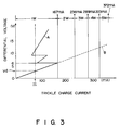
- Fig. 3 is a graph explaining a change of a trickle charge current during the trickle charge according to the present invention and during the trickle charge according to the conventional case.
- the axis of ordinates represents a differential voltage representing a difference between the voltage of the AC adapter 29 and the battery voltage of the battery 48
- the axis of abscissas represents a trickle charge current.
- Symbol "It” denotes a desirable trickle charge current value
- symbol “Vd” denotes a differential voltage (about 3V) in a normal operating state
- the "1W, 2W, " denote the wattage of the trickle charge resistor.
- FIG. 3 is a value necessary to prevent the elements located around the resistor from being adversely affected by heat produced during the trickle charge current flows into the resistor.
- the trickle charge resistor must have a wattage equal to or larger than 2W. If the resistor has a wattage smaller than 2W, the elements located around the resistor will be adversely affected by the heat produced in the resistor.
- linear line B including solid and broken lines represents a change of the trickle charge current during the trickle charge according to the conventional case
- bent line A (as a solid line) represents a change of the trickle charge current during the trickle charge according to the present invention.
- Figs. 4A and 4B are flowcharts showing the trickle charge control performed by the CPU 51 of the power source controller 50
- Fig. 5 is a flowchart showing the timer interruption processing executed by the CPU 51.
- the CPU 51 of the power supply controller 50 executes the trickle charge control program stored in ROM 53.
- the timer interruption processing is performed by the timer interruption cycle set by the execution of the trickle charge control program.
- a timer interrupt flag indicates whether or not the trickle charge control is executed. As will be described later, the timer interruption processing is executed every the predetermined time of 65 ms, and the timer interrupt flag is set to be "1" in each timer interruption processing. In other words, the trickle charge control is executed every 65 ms.
- a count value corresponding to a content of memory area in the RAM 52 assigned as a counter is referred to.
- the count value of the counter is one of “0,” “1,” “2” and “3.”
- the count value is repeatedly counted up in the order of "0,” “1,” “2” and “3.”
- the count value is incremented by 1 every 65 ms. Therefore, an execution period of the trickle charge is set every period of 260 ms (65 ms ⁇ 4).
- a duty register is a 4 bit register representing an execution period of the trickle charge at periods of 260 ms.
- the register value (in a hexadecimal number) of the duty register is "0" (corresponding to "0000” in a binary number)
- no trickle charge is executed during the period of 260 ms.
- the register value of the duty register is "1" (corresponding to "0001" in a binary number)
- the trickle charge is executed for about 65 ms from the start of the period of 260 ms.
- the trickle charge is executed for about 130 ms (65 ms ⁇ 2) from the start of the period of 260 ms.
- the register value of the duty register is "F” (corresponding to "1111” in a binary number)
- the trickle charge is executed during the period of 260 ms.
- step S1 it is determined whether or not the FET switch 70 is on, i.e., whether or not a voltage is supplied to each component of the computer system by either the AD adapter 29 or the battery 48. If the FET switch 70 is on, the timer interrupt cycle is set to be 65 ms, for example, in step S2. Further, in step S3, the count value of the counter is set to be "0.”
- step S4 it is determined whether or not the timer interrupt flag is "1." Since the timer interrupt cycle is set to be 65 ms in step S2, the timer interruption processing shown in Fig. 5 is executed at periods of 65 ms. In the timer interruption processing, the timer interrupt flag is set to be "1" in step F1. Therefore, the processing step S4 and sequent steps are not carried out until the processing of step F1 is executed.
- step S4 if the timer interrupt flag is "1," the timer interrupt flag is set to be “0” in step S5. In subsequent step S6, it is determined whether or not the count value of the counter is "0.”
- step S6 if the count value of the counter is "0," it is determined that the present time corresponds to the start time of the period of 260 ms. Hence, processes of steps 7-16 are executed so as to set the execution period of the trickle charge.
- step S7 it is determined whether or not the AC adapter 29 is connected to the computer system.
- step S8 it is determined whether or not the battery 48 is incorporated in the computer system.
- step S9 the duty register value of the duty register is set to be "0" (step S9). That is, the trickle charge is not performed.
- step S10 an adapter voltage value representing the adapter voltage of the AC adapter 29 output from the voltage detector 61 to the A/D converter 56 is read.
- step S11 a battery voltage value representing the battery voltage of the battery 48 output from the voltage detector 62 to the A/D converter 56 is read.
- step S12 a differential voltage value representing a difference between the adapter voltage value and the battery voltage value (adapter voltage value - battery voltage value) is compared with a reference voltage value of e.g., 6V.
- a reference voltage value of 6V corresponds to the upper limit value of the trickle charge resistor which has a wattage of 1.
- step S12 If the differential voltage value is equal to or smaller than 6V in step S12, the duty register value is set to be "F,” i.e., "1111" in step S13. This represents that the trickle charge is executed during the period of 260 ms.
- step S14 If the differential voltage value is larger than 6V in step S12, it is determined whether or not the differential voltage value is larger than 9V (step S14). If the differential voltage value is equal to or smaller than 9V in step S14, the duty register value is set to be "3," i.e., "0011" in step S15. If, on the other hand, the differential voltage value is larger than 9V in step S14, the duty register value is set to be "1," i.e., "0001" in step S16.
- step S17 If the count value is not "0" in step S6 or if the processing of steps S9, S13, S15 or S16 has completed, then processing of step S17 is executed.
- step S17 it is determined whether or not the least significant bit (LSB) of the duty register is "1.” If the least significant bit is "1" in step S17, a control signal to execute the trickle charge is produced in step S19.
- the control signal used for turning on the FET switch 73 is output from the output port 55 to the FET switch 73. Accordingly, a trickle charge current is supplied from the AC adapter 29 to the battery 48 through the trickle charge resistor 66, thus starting the trickle charge.
- step S17 If the least significant bit of the duty register is not "1" but “0" in step S17, a control signal to stop the trickle charge is produced in step S18.
- the control signal for turning off the FET switch 73 is supplied from the output port 55 to the FET switch 73. Accordingly, the AC adapter 29 is prevented from supplying the trickle charge current to the battery 48, thus stopping the trickle charge.
- step S20 one bit rotation is executed for the duty register, so that the duty register value of the duty register is rotated to the right by one bit.
- step S21 the count value of the counter is incremented by 1. As mentioned above, the count value is repeatedly counted up in the order of "0,” “1,” "2” and “3.” Therefore, if the counter value is "3,” it is set to be "0" in step S21. Thereafter, the processing flow returns to step S3, so that the trickle charge control mentioned above is performed every period of 65 ms.
- Fig. 6 shows the case where a hexadecimal number of "3" (i.e., "0011") is set as the duty register value. It should be noted that the count value is incremented by 1 every the period of 65 ms.
- step S17 when the count value of the counter is "0,” it is determined in step S17 that the least significant bit of the duty register is “1.” Therefore, the trickle charge is continued (step S19).
- step S20 the duty register value "0011” is changed to "1001” by one bit rotation to the right, and in step S21, the count value "0" is incremented by 1, thereby to obtain "1.”
- step S17 After 65 ms elapses, the count value of the counter is "1," it is determined in step S17 that the least significant bit of the duty register is “1.” In this case, the trickle charge is continued (step S19). The duty register value "1001” is changed to “1100” by one bit rotation to the right, and the count value "1” is incremented by 1, thereby to obtain "2.”
- step S17 After further 65 ms elapses (i.e., after 130 ms elapses from the start of the trickle charge control), the count value of the counter is "2," it is determined in step S17 that the least significant bit of the duty register is "0.” In this case, the trickle charge is stopped (step S18).
- the duty register value "1100” is changed to "0110” by one bit rotation to the right, and the count value "2" is incremented by 1, thereby to obtain "3.”
- step S17 After further 65 ms elapses (i.e., after 195 ms elapses from the start of the trickle charge control), the count value of the counter is "3," it is determined in step S17 that the least significant bit of the duty register is "0". In this case, stopping of the trickle charge is continued (step S18).
- the duty register value "0110” is changed to "0011” by one bit rotation to the right, and the count value "3" is changed to "0” by increment of the count value.
- step S6 After further 65 ms elapses (i.e., after 260 ms elapses from the start of the trickle charge control), it is determined in step S6 that the count value of the counter is "0.” Therefore, steps S7-S16 are executed, wherein a new duty register value is set in the register and the trickle charge control is executed in accordance with the new duty register value.
- trickle charge is started or stopped at the predetermined timings based on a differential voltage. Even when the differential voltage increases, a trickle charge current is close to the desirable value "It" at all times, as is indicated by the bent line A in Fig. 3. Since the wattage of the trickle charge resistor 66 need not be large (1W in the case of the present embodiment), the resistor 66 of a small size can be used.
- the trickle charge is started or stopped at intervals set on the basis of the differential voltage representing the difference between the adapter voltage and the battery voltage.
- the trickle charge can be started or stopped either in multi-steps or linearly on the basis of the differential voltage.
Landscapes
- Engineering & Computer Science (AREA)
- Power Engineering (AREA)
- Theoretical Computer Science (AREA)
- Physics & Mathematics (AREA)
- General Engineering & Computer Science (AREA)
- General Physics & Mathematics (AREA)
- Charge And Discharge Circuits For Batteries Or The Like (AREA)
- Power Sources (AREA)
Claims (10)
- Ein Gerät für eine Stromversorgungsregelung mit einer wiederaufladbaren Batterie (48), einem Versorgungsmittel (29) und einem Widerstand (66) zwischen dem Versorgungsmittel (29) und der Batterie (48), um einen Dauerladungsstrom durch den Widerstand (66) der Batterie (48) zuzuführen, und Regelungsmittel (50, 61, 62, 73) zum Abtasten von Spannungen der Batterie (48) zu vorbestimmten Zeiten während eines Ladens der Batterie (48),
dadurch gekennzeichnet, daß
das Regelungsmittel (50, 61, 62, 73) weiter angepaßt ist, um Spannungen des Versorgungsmittels (29) zu vorbestimmten Zeiten abzutasten und um eine Spannungsdifferenz zwischen den jeweiligen abgetasteten Spannungen des Versorgungsmittels (29) und der Batterie (48) bilden,
daß die so gebildete Spannungsdifferenz einem Dauerladungsstromwert entspricht, und
daß das Regelungsmittel (50, 61, 62, 73) den Dauerladungsstrom reduziert oder stoppt, wenn die Spannungsdifferenz oberhalb eines vorbestimmten Wertes liegt, der dem oberen Grenzwert des Dauerladungswiderstands (66) bezüglich dessen Wattleistung entspricht. - Das Gerät nach Anspruch 1, dadurch gekennzeichnet, daß das Regelungsmittel (50, 61, 62, 73) eine Ausführungsperiode für eine Dauerladung und eine Stoppperiode für eine Dauerladung innerhalb einer vorbestimmten Periode auf der Grundlage des Spannungsdifferenzwertes einstellt.
- Das Gerät nach Anspruch 2, dadurch gekennzeichnet, daß, wenn der Spannungsdifferenzwert gleich einem ersten Einstellwert oder kleiner als ein erster Einstellwert ist, wobei nur die Ausführungsperiode für eine Dauerladung innerhalb der vorbestimmten Periode eingestellt wird, die Dauerladung während der vorbestimmten Periode fortgesetzt wird.
- Das Gerät nach Anspruch 2, dadurch gekennzeichnet, daß, wenn der Spannungsdifferenzwert größer als ein erster Einstellwert und gleich einem zweiten Einstellwert oder kleiner als ein zweiter Einstellwert ist, die Ausführungsperiode für eine Dauerladung, die innerhalb der vorbestimmten Periode eingestellt wird, mit der Stopperiode für eine Dauerladung übereinstimmt, die innerhalb der vorbestimmten Periode eingestellt wird.
- Das Gerät nach Anspruch 2, dadurch gekennzeichnet, daß, wenn der Spannungsdifferenzwert größer als ein zweiter Einstellwert ist, die Ausführungsperiode für eine Dauerladung, die innerhalb der vorbestimmten Periode eingestellt wird, 1/3 der Stopperiode für eine Dauerladung beträgt, die innerhalb der Periode eingestellt wird.
- Ein Verfahren für eine Stromversorgungsregelung, welche die Schritte umfaßt, daß bestimmt wird, ob eine wiederaufladbare Batterie (48) eingebaut ist oder nicht und ob ein Adapter (29), um einen Dauerladungsstrom zuzuführen, angeschlossen ist oder nicht;
eine Dauerladung der Batterie (48) durch einen Widerstand (66), der zwischen den Adapter (29) und die Batterie (48) geschaltet ist, begonnen wird, wenn die Batterie (48) eingebaut ist und der Adapter (29) angeschlossen ist;
Spannungen der Batterie (48) und des Adapters (29) zu vorbestimmten Zeiten während der Dauerladung der Batterie (48) abgetastet werden;
eine Spannungsdifferenz zwischen den jeweiligen abgetasteten Spannungen des Adapters (29) und der Batterie (48) gebildet wird, wobei die Spannungsdifferenz dem Dauerladungsstromwert entspricht; und
die Dauerladung reduziert oder gestoppt wird, wenn die Spannungsdifferenz oberhalb eines vorbestimmten Wertes liegt, welcher der oberen Grenze des Dauerladungswiderstands (66) bezüglich dessen Wattleistung entspricht. - Das Verfahren nach Anspruch 6, dadurch gekennzeichnet, daß eine Ausführungsperiode für eine Dauerladung und eine Stopperiode für eine Dauerladung innerhalb einer vorbestimmten Periode auf der Grundlage der Spannungsdifferenz eingestellt werden.
- Das Verfahren nach Anspruch 7, dadurch gekennzeichnet, daß, wenn der Spannungsdifferenzwert gleich einem ersten Einstellwert oder kleiner als ein erster Einstellwert ist, wobei nur die Ausführungsperiode für eine Dauerladung innerhalb der vorbestimmten Periode eingestellt wird, die Dauerladung während der vorbestimmten Periode fortgesetzt wird.
- Das Verfahren nach Anspruch 7, dadurch gekennzeichnet, daß, wenn der Spannungsdifferenzwert größer als ein erster Einstellwert ist und gleich einem zweiten Einstellwert oder kleiner als ein zweiter Einstellwert ist, die Ausführungsperiode für eine Dauerladung, die innerhalb der vorbestimmten Periode eingestellt wird, mit der Stopperiode für eine Dauerladung übereinstimmt, die innerhalb der vorbestimmten Periode eingestellt wird.
- Das Verfahren nach Anspruch 7, dadurch gekennzeichnet, daß, wenn der Spannungsdifferenzwert größer als ein zweiter Einstellwert ist, die Ausführungsperiode für eine Dauerladung, die innerhalb der vorbestimmten Periode eingestellt wird, 1/3 der Stopperiode für eine Dauerladung beträgt, die innerhalb der vorbestimmten Periode eingestellt wird.
Applications Claiming Priority (2)
| Application Number | Priority Date | Filing Date | Title |
|---|---|---|---|
| JP2301687A JPH04178121A (ja) | 1990-11-07 | 1990-11-07 | トリクル充電制御装置 |
| JP301687/90 | 1990-11-07 |
Publications (3)
| Publication Number | Publication Date |
|---|---|
| EP0484757A2 EP0484757A2 (de) | 1992-05-13 |
| EP0484757A3 EP0484757A3 (en) | 1992-09-02 |
| EP0484757B1 true EP0484757B1 (de) | 1995-04-05 |
Family
ID=17899935
Family Applications (1)
| Application Number | Title | Priority Date | Filing Date |
|---|---|---|---|
| EP91118187A Expired - Lifetime EP0484757B1 (de) | 1990-11-07 | 1991-10-24 | Verfahren und Schaltungsanordnung für Stromversorgung |
Country Status (6)
| Country | Link |
|---|---|
| US (1) | US5325039A (de) |
| EP (1) | EP0484757B1 (de) |
| JP (1) | JPH04178121A (de) |
| KR (1) | KR940006804B1 (de) |
| DE (1) | DE69108672T2 (de) |
| TW (1) | TW327005U (de) |
Families Citing this family (6)
| Publication number | Priority date | Publication date | Assignee | Title |
|---|---|---|---|---|
| US5331268A (en) * | 1993-08-02 | 1994-07-19 | Motorola, Inc. | Method and apparatus for dynamically charging a battery |
| US6104170A (en) * | 1998-12-23 | 2000-08-15 | Fairchild Semiconductor Corporation | Method and circuit for preventing oscillations in a battery charger |
| US6194874B1 (en) | 1999-03-17 | 2001-02-27 | Telefonaktiebolaget Lm Ericsson (Publ) | System and method for maintenance charging of battery cells |
| JP3886835B2 (ja) * | 2002-03-25 | 2007-02-28 | 株式会社マキタ | 充電システム |
| US8319479B2 (en) * | 2010-03-23 | 2012-11-27 | Ememory Technology Inc. | Method of estimating battery recharge time and related device |
| TWI397240B (zh) * | 2010-05-03 | 2013-05-21 | Ememory Technology Inc | 智慧型電池裝置、對智慧型電池裝置的電池組充電的方法及智慧型電池裝置中產生近似於電池平均充滿時間的方法 |
Family Cites Families (10)
| Publication number | Priority date | Publication date | Assignee | Title |
|---|---|---|---|---|
| US3766463A (en) * | 1971-12-17 | 1973-10-16 | M Ruben | Battery charging circuit with scr{40 s triggered by unijunction circuits having means for preventing unijunction from being latched on |
| US4019111A (en) * | 1975-05-14 | 1977-04-19 | Introl Corporation | Battery charger with automatic change from current to voltage mode control |
| US4031451A (en) * | 1976-02-23 | 1977-06-21 | Alkon Laboratories, Inc. | Charging circuit with SCR's triggered by pedestal and cosine modified ramp unijunction circuit having means for current limiting by controlling pedestal level |
| DE2918064A1 (de) * | 1978-05-08 | 1979-11-22 | Ebauches Sa | Vorrichtung zum laden eines akkumulators durch eine quelle elektrischer energie, insbesondere fuer eine elektronische uhr |
| EP0005841B1 (de) * | 1978-05-31 | 1984-06-06 | Black & Decker Inc. | Verfahren zum Laden eines Akkumulators und Vorrichtung für dieses Verfahren |
| JPS56115141A (en) * | 1980-02-14 | 1981-09-10 | Matsushita Electric Works Ltd | Automatic voltage changing type charger |
| US4716354A (en) * | 1985-11-12 | 1987-12-29 | Norand Corporation | Automatic voltage regulator means providing a dual low power responsive and output-voltage-controlling regulator signal particularly for a plural source battery powered system |
| US4754160A (en) * | 1984-08-23 | 1988-06-28 | Intersil, Inc. | Power supply switching circuit |
| US4730121B1 (en) * | 1987-03-11 | 1998-09-15 | Dallas Semiconductor | Power controller for circuits with battery backup |
| JPH088748B2 (ja) * | 1988-11-11 | 1996-01-29 | 三洋電機株式会社 | 満充電検出回路 |
-
1990
- 1990-11-07 JP JP2301687A patent/JPH04178121A/ja active Pending
-
1991
- 1991-10-24 DE DE69108672T patent/DE69108672T2/de not_active Expired - Fee Related
- 1991-10-24 EP EP91118187A patent/EP0484757B1/de not_active Expired - Lifetime
- 1991-10-30 US US07/784,714 patent/US5325039A/en not_active Expired - Fee Related
- 1991-11-04 TW TW084204011U patent/TW327005U/zh unknown
- 1991-11-07 KR KR1019910019704A patent/KR940006804B1/ko not_active Expired - Fee Related
Also Published As
| Publication number | Publication date |
|---|---|
| DE69108672T2 (de) | 1995-08-10 |
| KR920010400A (ko) | 1992-06-26 |
| TW327005U (en) | 1998-02-11 |
| DE69108672D1 (de) | 1995-05-11 |
| EP0484757A2 (de) | 1992-05-13 |
| EP0484757A3 (en) | 1992-09-02 |
| KR940006804B1 (ko) | 1994-07-27 |
| JPH04178121A (ja) | 1992-06-25 |
| US5325039A (en) | 1994-06-28 |
Similar Documents
| Publication | Publication Date | Title |
|---|---|---|
| US5818200A (en) | Dual smart battery detection system and method for portable computers | |
| US6714016B2 (en) | Method for displaying information concerning power consumption and electronic device | |
| US5539298A (en) | Pulse charge technique to trickle charge a rechargeable battery | |
| CA2118818C (en) | Battery pack including static memory and a timer for charge management | |
| US6483274B2 (en) | Device and method for displaying charge capacity information of smart battery | |
| JP2928431B2 (ja) | 補助バッテリ装置および充放電制御方法 | |
| US5955797A (en) | Portable computer being powered by either a battery pack or an AC adapter | |
| CN102841668B (zh) | 具备计时电路的便携式电子设备的电力系统 | |
| JP3592919B2 (ja) | バッテリタイプ自動感知装置 | |
| US5523670A (en) | Method and apparatus for controlling power supply | |
| EP2256897A1 (de) | Batteriepack und Laden desselben | |
| EP0484745A2 (de) | Gerät zur Rechnerstromversorgungssteuerung | |
| US20050174710A1 (en) | Electronic device and power supply control method | |
| EP0496537A2 (de) | Einrichtung zur Überwachung des Ladezustandes einer Batterie | |
| WO1998002933A1 (en) | Battery operating system | |
| US5424800A (en) | Camera having solar battery and secondary battery | |
| US6163132A (en) | Battery charging status indicator apparatus | |
| JPH11191437A (ja) | 電池識別装置およびその識別方法 | |
| EP0484757B1 (de) | Verfahren und Schaltungsanordnung für Stromversorgung | |
| EP0560510A1 (de) | Batteriebetriebener Rechner und Batterieleistungssteuerungsverfahren für einen solchen Rechner | |
| US5880576A (en) | Charging apparatus for controlling supplement of electric current to a rechargeable battery | |
| JP2004159382A (ja) | 電子機器 | |
| JP2000083325A (ja) | バッテリー状態監視回路、バッテリー装置及び該バッテリー装置を搭載した電子機器 | |
| JP2997584B2 (ja) | 電源制御装置 | |
| JP3322747B2 (ja) | トリクル充電電流切替装置 |
Legal Events
| Date | Code | Title | Description |
|---|---|---|---|
| PUAI | Public reference made under article 153(3) epc to a published international application that has entered the european phase |
Free format text: ORIGINAL CODE: 0009012 |
|
| 17P | Request for examination filed |
Effective date: 19911121 |
|
| AK | Designated contracting states |
Kind code of ref document: A2 Designated state(s): DE FR GB |
|
| PUAL | Search report despatched |
Free format text: ORIGINAL CODE: 0009013 |
|
| AK | Designated contracting states |
Kind code of ref document: A3 Designated state(s): DE FR GB |
|
| 17Q | First examination report despatched |
Effective date: 19931119 |
|
| GRAA | (expected) grant |
Free format text: ORIGINAL CODE: 0009210 |
|
| AK | Designated contracting states |
Kind code of ref document: B1 Designated state(s): DE FR GB |
|
| REF | Corresponds to: |
Ref document number: 69108672 Country of ref document: DE Date of ref document: 19950511 |
|
| ET | Fr: translation filed | ||
| PLBE | No opposition filed within time limit |
Free format text: ORIGINAL CODE: 0009261 |
|
| STAA | Information on the status of an ep patent application or granted ep patent |
Free format text: STATUS: NO OPPOSITION FILED WITHIN TIME LIMIT |
|
| 26N | No opposition filed | ||
| PGFP | Annual fee paid to national office [announced via postgrant information from national office to epo] |
Ref country code: GB Payment date: 19971015 Year of fee payment: 7 |
|
| PGFP | Annual fee paid to national office [announced via postgrant information from national office to epo] |
Ref country code: DE Payment date: 19971031 Year of fee payment: 7 |
|
| PGFP | Annual fee paid to national office [announced via postgrant information from national office to epo] |
Ref country code: FR Payment date: 19981009 Year of fee payment: 8 |
|
| PG25 | Lapsed in a contracting state [announced via postgrant information from national office to epo] |
Ref country code: GB Free format text: LAPSE BECAUSE OF NON-PAYMENT OF DUE FEES Effective date: 19981024 |
|
| GBPC | Gb: european patent ceased through non-payment of renewal fee |
Effective date: 19981024 |
|
| PG25 | Lapsed in a contracting state [announced via postgrant information from national office to epo] |
Ref country code: DE Free format text: LAPSE BECAUSE OF NON-PAYMENT OF DUE FEES Effective date: 19990803 |
|
| PG25 | Lapsed in a contracting state [announced via postgrant information from national office to epo] |
Ref country code: FR Free format text: LAPSE BECAUSE OF NON-PAYMENT OF DUE FEES Effective date: 20000630 |
|
| REG | Reference to a national code |
Ref country code: FR Ref legal event code: ST |