EP0484780A1 - Gestochenes Servomuster und Verfahren zur Positionierung eines optisch-magnetischen Lese-Schreibkopfes - Google Patents
Gestochenes Servomuster und Verfahren zur Positionierung eines optisch-magnetischen Lese-Schreibkopfes Download PDFInfo
- Publication number
- EP0484780A1 EP0484780A1 EP91118340A EP91118340A EP0484780A1 EP 0484780 A1 EP0484780 A1 EP 0484780A1 EP 91118340 A EP91118340 A EP 91118340A EP 91118340 A EP91118340 A EP 91118340A EP 0484780 A1 EP0484780 A1 EP 0484780A1
- Authority
- EP
- European Patent Office
- Prior art keywords
- media
- optical
- reflective
- diskette
- servo
- Prior art date
- Legal status (The legal status is an assumption and is not a legal conclusion. Google has not performed a legal analysis and makes no representation as to the accuracy of the status listed.)
- Withdrawn
Links
- 238000000034 method Methods 0.000 title claims description 8
- 230000003287 optical effect Effects 0.000 claims abstract description 38
- 238000001514 detection method Methods 0.000 claims description 13
- 238000004049 embossing Methods 0.000 claims description 4
- 238000010329 laser etching Methods 0.000 claims description 4
- 239000000463 material Substances 0.000 abstract description 6
- 238000000576 coating method Methods 0.000 abstract description 5
- 239000011248 coating agent Substances 0.000 abstract description 4
- 230000008901 benefit Effects 0.000 description 5
- 238000005286 illumination Methods 0.000 description 4
- 238000002310 reflectometry Methods 0.000 description 4
- 230000007547 defect Effects 0.000 description 3
- 230000000881 depressing effect Effects 0.000 description 3
- 230000000994 depressogenic effect Effects 0.000 description 3
- 230000000694 effects Effects 0.000 description 3
- AJCDFVKYMIUXCR-UHFFFAOYSA-N oxobarium;oxo(oxoferriooxy)iron Chemical compound [Ba]=O.O=[Fe]O[Fe]=O.O=[Fe]O[Fe]=O.O=[Fe]O[Fe]=O.O=[Fe]O[Fe]=O.O=[Fe]O[Fe]=O.O=[Fe]O[Fe]=O AJCDFVKYMIUXCR-UHFFFAOYSA-N 0.000 description 3
- 230000004075 alteration Effects 0.000 description 2
- QVQLCTNNEUAWMS-UHFFFAOYSA-N barium oxide Chemical compound [Ba]=O QVQLCTNNEUAWMS-UHFFFAOYSA-N 0.000 description 2
- 238000005516 engineering process Methods 0.000 description 2
- 230000005012 migration Effects 0.000 description 2
- 238000013508 migration Methods 0.000 description 2
- 230000004048 modification Effects 0.000 description 2
- 238000012986 modification Methods 0.000 description 2
- 238000000926 separation method Methods 0.000 description 2
- 239000000654 additive Substances 0.000 description 1
- 230000000996 additive effect Effects 0.000 description 1
- 230000032683 aging Effects 0.000 description 1
- 230000004397 blinking Effects 0.000 description 1
- 230000008859 change Effects 0.000 description 1
- 150000001875 compounds Chemical class 0.000 description 1
- 238000011109 contamination Methods 0.000 description 1
- 230000008878 coupling Effects 0.000 description 1
- 238000010168 coupling process Methods 0.000 description 1
- 238000005859 coupling reaction Methods 0.000 description 1
- 238000013500 data storage Methods 0.000 description 1
- 230000001934 delay Effects 0.000 description 1
- 238000006073 displacement reaction Methods 0.000 description 1
- 239000000835 fiber Substances 0.000 description 1
- UQSXHKLRYXJYBZ-UHFFFAOYSA-N iron oxide Inorganic materials [Fe]=O UQSXHKLRYXJYBZ-UHFFFAOYSA-N 0.000 description 1
- NDLPOXTZKUMGOV-UHFFFAOYSA-N oxo(oxoferriooxy)iron hydrate Chemical compound O.O=[Fe]O[Fe]=O NDLPOXTZKUMGOV-UHFFFAOYSA-N 0.000 description 1
- 230000008569 process Effects 0.000 description 1
- 238000011084 recovery Methods 0.000 description 1
- 229910000859 α-Fe Inorganic materials 0.000 description 1
Images
Classifications
-
- G—PHYSICS
- G11—INFORMATION STORAGE
- G11B—INFORMATION STORAGE BASED ON RELATIVE MOVEMENT BETWEEN RECORD CARRIER AND TRANSDUCER
- G11B27/00—Editing; Indexing; Addressing; Timing or synchronising; Monitoring; Measuring tape travel
- G11B27/10—Indexing; Addressing; Timing or synchronising; Measuring tape travel
- G11B27/19—Indexing; Addressing; Timing or synchronising; Measuring tape travel by using information detectable on the record carrier
- G11B27/24—Indexing; Addressing; Timing or synchronising; Measuring tape travel by using information detectable on the record carrier by sensing features on the record carrier other than the transducing track ; sensing signals or marks recorded by another method than the main recording
-
- G—PHYSICS
- G11—INFORMATION STORAGE
- G11B—INFORMATION STORAGE BASED ON RELATIVE MOVEMENT BETWEEN RECORD CARRIER AND TRANSDUCER
- G11B5/00—Recording by magnetisation or demagnetisation of a record carrier; Reproducing by magnetic means; Record carriers therefor
- G11B5/48—Disposition or mounting of heads or head supports relative to record carriers ; arrangements of heads, e.g. for scanning the record carrier to increase the relative speed
- G11B5/58—Disposition or mounting of heads or head supports relative to record carriers ; arrangements of heads, e.g. for scanning the record carrier to increase the relative speed with provision for moving the head for the purpose of maintaining alignment of the head relative to the record carrier during transducing operation, e.g. to compensate for surface irregularities of the latter or for track following
- G11B5/596—Disposition or mounting of heads or head supports relative to record carriers ; arrangements of heads, e.g. for scanning the record carrier to increase the relative speed with provision for moving the head for the purpose of maintaining alignment of the head relative to the record carrier during transducing operation, e.g. to compensate for surface irregularities of the latter or for track following for track following on disks
- G11B5/59677—Disposition or mounting of heads or head supports relative to record carriers ; arrangements of heads, e.g. for scanning the record carrier to increase the relative speed with provision for moving the head for the purpose of maintaining alignment of the head relative to the record carrier during transducing operation, e.g. to compensate for surface irregularities of the latter or for track following for track following on disks with optical servo tracking
-
- G—PHYSICS
- G11—INFORMATION STORAGE
- G11B—INFORMATION STORAGE BASED ON RELATIVE MOVEMENT BETWEEN RECORD CARRIER AND TRANSDUCER
- G11B5/00—Recording by magnetisation or demagnetisation of a record carrier; Reproducing by magnetic means; Record carriers therefor
- G11B5/74—Record carriers characterised by the form, e.g. sheet shaped to wrap around a drum
- G11B5/82—Disk carriers
- G11B5/825—Disk carriers flexible discs
Definitions
- the invention relates generally to magnetic disk drives and more specifically to positioning optical-magnetic read/write heads in high track density drives and diskettes.
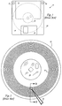
- Fig. 1 is a prior art diskette, referred to by the general reference numeral 10, comprising a jacket 12, a label 14, a shutter 16, and a media 18.
- a liner is disposed within jacket 12 and is made of a material that lubricates and cleans media 18.
- Fig. 2 is the prior art media of the diskette 10 of Fig. 1, shown without the jacket 12 and liner.
- Media 18 is typically coated with ferrite oxide.
- Media 18 comprises a plurality of concentric optically visible servo tracks 26. These optical servo tracks 26 are used to accurately position a read/write head assembly 28.
- Optical servo tracks 26 are embossed on media 18 by laser etching an unbroken concentric ring. The embossed areas (tracks 26) of media 18 will reflect less light that will the un-embossed areas.
- Fig. 3 is a cross-sectional view of the prior art media showing the vertical relief of a plurality of "valleys,” caused by the above embossing, and a plurality of resulting “hills” that represent areas of un-embossed media.
- a modulator 32 comprises a frequency source, a mixer to combine the frequency source with automatic gain control (AGC) illumination level, a filter to eliminate harmonics and to generate a pure sine wave, and a DC restore circuit to control the baseline of the sinewave.
- Head assembly 28 comprises an LED 34 and a light detector 36 to pick up reflected light.
- a filter 38 removes unmodulated light detected by detector 36.
- Light from head assembly 28 is bounced off of media 18 and used to detect whether the head assembly 28 is positioned over a hill or over a valley, or somewhere in between.
- the signals are then processed by a front-end electronics sub-system.
- Media defects, dirt, and contamination on the surface of the media can create false position readings by the head.
- a large dynamic range is required by the front-end electronics sub-system to pass irrelevant reflected light without losing the information contained in the light reflected off of the media.
- the amount of irrelevant reflected light varies from drive to drive and from media to media.
- a calibration process must therefore be included in the drive to determine how much light is from the optical servo tracks and how much is not. This calibration degrades system performance, as it delays the availability of the diskette to a system.
- Prior art systems modulate the LED 34 to produce a modulated light that can be distinguished by the detector 36 from background light. But modulating the LED 34 current induces electrical and electromagnetic interference at a point very near the very sensitive magnetic head.
- the DC restore circuit in modulator 32 is used to control the amount of DC illumination generated by LED 34. DC illumination generates heat (from the LED 34), but provides no useful servo readback information. The amount of light that can be provided by LED 34 is limited by the total power that can be dissipated by the LED 34, whether that power is ultimately used to create useful information or not.
- the DC restore circuit guarantees highly efficient illumination by assuring a low amount of DC without clipping of the sine wave.
- the modulation of LED 34 (or any similar light source in the prior art) requires electrical shielding of LED 34 and its power supply lines. The shielding is necessary to reduce electromagnetic coupling into the magnetic head and its leads.
- the prior art requires modulated light sources to swing from zero to full amplitude at the modulating frequency (about twenty kilohertz).
- the peak levels are, in turn, modulated with a low frequency to adjust for track reflectivity variations in the media.
- the present invention described below, requires the light source to vary only to follow reflectivity variations.
- an embodiment of the present invention is a diskette comprising a jacket, a liner material disposed within said jacket, a flat circular media having a magnetic coating on both sides disposed within said liner material, a hub attached at the center of said media, a plurality of optical positioning tracks on at least one of said sides of said media that have stitched patterns that will wink on-and-off at twenty kilohertz in the presence of a constant, unmodulated light source.
- An advantage of the present invention is that simplified circuits may be employed to drive the light sources in an optical-magnetic head.
- Another advantage of the present invention is that no electromagnetic interference with the operation of a magnetic head will be caused by the light source or its lead wires.
- Another advantage of the present invention is that a greater amount of light source power is used in the recovery of useful positioning information.
- Another advantage of the present invention is that the positioning accuracy is improved and is less sensitive to particular common media defects and wear.
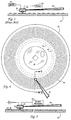
- Fig. 4 illustrates a media 42 and a hub 44 of the present invention that overcomes the problems above and is assembled into a diskette assembly similar to diskette 10 (Fig. 1).
- the media 42 comprises a barium ferrite coating on both top and bottom surfaces (not shown for clarity in showing the other elements below), a plurality of concentric optical servo tracks 46, a media type code track 48, and a reference cylinder 50.
- Barium ferrite is preferred over ferric oxide for the coatings, because barium ferrite will support higher recording densities.
- the optical servo tracks 46 and reference cylinder 48 comprise a dashed pattern of reflective and non-reflective regions, rather than the continuously non-reflective tracks of the prior art (as is exemplified by media 18 in Fig. 2).
- Reference cylinder 48 provides a zero reference point for track zero calibration and track seeking among tracks 46.
- the dashed patterns will appear to blink on and off (for example, at twenty kilohertz).
- RPM revolutions per minute
- the dark areas of the optical servo tracks 46 are preferably embossed on media 42 by laser etching. The laser etching cuts small valleys, or grooves, that have rough floors that do not reflect light very well. All the un-embossed areas of media 42 will reflect light efficiently.
- Fig. 5 illustrates that head assembly 52 carries a light source 54 and a light detector 56.
- a constant power source e.g., a battery
- Light source 54 is preferably an LED, however, a fiber optic cable could be used to pipe light in from a bulkier source than an LED.
- a twenty kilohertz bandpass filter 58 removes background light and spurious reflections, such as those associated with common media defects.
- a plurality of hills 60 and valleys 62 are shown to exist on one side only of media 42.
- the optical servo tracks 46 being on one side will serve to position the heads on both sides by virtue of the usual practice of ganging the heads together on a common actuator arm.
- the detector 56 has a pulsed output when the tip of head assembly 52 is positioned over an optical servo track.
- Detector 56 has a diamond-shaped detection area (as described below for Fig. 6).
- the dashed pattern of the optical servo tracks 46 is such that a 50% duty cycle (dashes substantially equal to the space between them) is detected at a frequency of twenty kilohertz. Background and other spurious light will have frequency components significantly apart from twenty kilohertz.
- Spurious light will be blocked by the bandpass filter 58.
- Light reflected from the un-embossed areas of media 42 produce frequency components primarily at the rotational speed of the media (720 RPM), which is twelve hertz, and also at the second harmonic of 24 Hz.
- a relatively simple bandpass filter 58 will give good results, due to the above degree of frequency separation. (The frequency separation described will be true for any rotational speed, not just 720 RPM.)
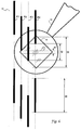
- Fig. 6 illustrates a detection area 70 belonging to detector 56 relative to several potential positions of a particular track 46. These positions are labelled P1-P4.
- Each track 46 is comprised of embossed, non-reflective ring segments (shown as the dark verical line segments along P1-P4).
- Each non-reflective line segment in P1 will take a time “t0" to pass a single point under head assembly 52.
- detection area 70 is diamond-shaped, and in position P2, and additional time “t1" is needed for the non-reflective line segments to pass leading edge to trailing edge in and out of detection area 70.
- Position P3 requires time “t2", which is longer than "t1". And in position P4, a maximum time "t3" will be added to "to”.
- the time it takes for a non-reflective dash, or "stitch" to pass its leading edge to its trailing edge under the diamond-shaped detection area will be maximum when the stitch passes squarely under the center of the detector.
- the leading edge of a stitch will enter the detection area later and the trailing edge will leave the detection area sooner.
- the duration is the time it takes a single point to travel the length of a single stitch.
- the duty cycle of the detector modulation will vary from 50% to zero.
- the amplitude of the twenty kilohertz signal from detector 56 will be maximum when the stitch passes squarely under the center of the detector, and will progressively decrease as the stitch passes closer to either edge. As the detector 56 moves away from the particular optical servo track 46, more light will be reflected by the media, but this increase in background light will be filtered away by the bandpass filter because it is essentially at DC frequency.
- Track-to-track reflectivity variations in the optical servo tracks 46 will effect the signal amplitude, since they are modulated by the stitched pattern.
- the magnetic area is 3.4 times larger than the track 46 area so burnish marks and wear marks are equally likely to occur in any area of the media 42. If the stitched pattern is created so that the magnetic performance of the non-reflective areas are significantly different than the reflective areas, unwanted modulation of the magnetic data may occur and degrade the data handling error rate of the system. This type of magnetic modulation is multiplicative modulation of the peak-to-peak amplitude of the magnetic data. Therefore, all frequencies present in the data are affected.
- the multiplication also called heterodyning introduces harmonics above and below each frequency contained in the magnetic data (sum-and-difference products).
- a 600 KHz magnetic data frequency will appear at both 580 KHz and 620 KHz, due to twenty kilohertz modulation.
- the third harmonic of twenty kilohertz will also produce 540 KHz and 660 KHz products.
- a readback signal will show a sudden increase in peak-to-peak amplitude at the trailing edge of a non-reflective area, and an equally sudden decrease in amplitude at the leading edge of a non-reflective area. This has the effect of shifting the detectable location of the magnetic data when the modulation occurs near the true peak.
- the prior art of modulating the light source creates an additive modulation, that injects the modulation frequency and not harmonics.
- the prior art appears to experience a baseline shift where magnetic information is added to the light source modulation.
- the effect of this modulation can be reduced by (1) maintaining the magnetic core over the magnetic data (un-embossed, reflective areas), and away from the optical servo tracks 46 (embossed, non-reflective areas); (2) providing the non-reflective parts in the optical servo track 46 area with the same magnetic performance as the reflective areas; and/or (3) providing a reflective region in the optical servo track 46 area that is as dead magnetically as the non-reflective areas.
- Maintaining the magnetic core over the magnetic data in between the optical servo tracks 46 is effective when the magnetic width of the head is narrow enough that the head will not be affected by the pattern within the optical servo tracks 46. This is an undesirable restriction and is difficult to maintain, because it requires narrower track width heads and higher bandwidth servos.
- the present inventors are still investigating the second technique, above. Providing a reflective region in the optical servo track 46 area that is as dead magnetically as the non-reflective areas is practical and places no additional constraints on the magnetic head or servo over the prior art.
- Media 42 is preferably impressed, rather than ablated to create the non-reflective areas in optical servo tracks 46.
- the pattern of the impression is to depress the media throughout an individual optical servo track 46 so that it is magnetically dead to the magnetic head everywhere in the track.
- the light and dark pattern is achieved by the finish achieved in the depressed areas.
- a smooth finish in the depressed areas will create a reflective area.
- a pitted finish will create a non-reflective area.
- the optical appearance of the smooth depressed area includes a dark band at either radial edge of the servo track 46, since the surface height will be changing in these areas and will scatter light.
- the width of individual optical servo tracks 46 is reduced in order to gain in the tradeoff with reduced magnetic modulation. Even though the cost of narrow optical servo tracks 46 is reduced modulation of the light produced by LED 54, the amount of reduced magnetic modulation to be realized is worth the price.
- each optical servo track 46 By depressing the entire concentric ring area of each optical servo track 46, scratches are less likely to occur. This extends medias 42 life and helps with servo tracking accuracy. If the stitched pattern were to be achieved by depressing the non-reflective areas and not by depressing the reflective areas, material (e.g., barium oxide coating) may be pulled out of the media 42 at the trailing edge of the non-reflective areas, which would cause a circumferential reflectivity change in a particular optical servo track 46.
- material e.g., barium oxide coating
Landscapes
- Moving Of The Head To Find And Align With The Track (AREA)
Applications Claiming Priority (2)
| Application Number | Priority Date | Filing Date | Title |
|---|---|---|---|
| US61103190A | 1990-11-09 | 1990-11-09 | |
| US611031 | 1990-11-09 |
Publications (1)
| Publication Number | Publication Date |
|---|---|
| EP0484780A1 true EP0484780A1 (de) | 1992-05-13 |
Family
ID=24447332
Family Applications (1)
| Application Number | Title | Priority Date | Filing Date |
|---|---|---|---|
| EP91118340A Withdrawn EP0484780A1 (de) | 1990-11-09 | 1991-10-28 | Gestochenes Servomuster und Verfahren zur Positionierung eines optisch-magnetischen Lese-Schreibkopfes |
Country Status (2)
| Country | Link |
|---|---|
| EP (1) | EP0484780A1 (de) |
| JP (1) | JPH04283443A (de) |
Cited By (13)
| Publication number | Priority date | Publication date | Assignee | Title |
|---|---|---|---|---|
| EP0650157A4 (de) * | 1992-11-06 | 1995-01-12 | Mitsubishi Chem Corp | Magnetisches aufzeichnungsmedium, dessen aufzeichnungs-/wiedergabeverfahren und informationsprozessor, der dieses medium und das verfahren gebraucht. |
| US6558774B1 (en) | 1999-08-17 | 2003-05-06 | Quantum Corporation | Multiple-layer backcoating for magnetic tape |
| US6741415B1 (en) | 1999-02-16 | 2004-05-25 | Quantum Corporation | Method of writing servo signal on magnetic tape |
| US6768608B2 (en) | 1998-03-24 | 2004-07-27 | Quantum Corporation | Multi-channel magnetic tape system having optical tracking servo |
| US6771450B1 (en) | 1999-02-17 | 2004-08-03 | Quantum Corporation | Method of writing servo signal on magnetic tape |
| US6940681B2 (en) | 2001-08-20 | 2005-09-06 | Quantum Corporation | Optical to magnetic alignment in magnetic tape system |
| US6940676B1 (en) | 2000-06-07 | 2005-09-06 | Quantum Corporation | Triple push-pull optical tracking system |
| US6961200B2 (en) | 1999-07-27 | 2005-11-01 | Quantum Corporation | Optical servo track identification on tape storage media |
| US6980390B2 (en) | 2003-02-05 | 2005-12-27 | Quantum Corporation | Magnetic media with embedded optical servo tracks |
| US7023650B2 (en) | 2001-11-07 | 2006-04-04 | Quantum Corporation | Optical sensor to recording head alignment |
| US7029726B1 (en) | 1999-07-27 | 2006-04-18 | Quantum Corporation | Method for forming a servo pattern on a magnetic tape |
| US7153366B1 (en) | 1998-03-24 | 2006-12-26 | Quantum Corporation | Systems and method for forming a servo pattern on a magnetic tape |
| US7187515B2 (en) | 2003-02-05 | 2007-03-06 | Quantum Corporation | Method and system for tracking magnetic media with embedded optical servo tracks |
Citations (2)
| Publication number | Priority date | Publication date | Assignee | Title |
|---|---|---|---|---|
| FR2347744A1 (fr) * | 1976-04-10 | 1977-11-04 | Philips Nv | Porteur d'information muni d'une couche d'emmagasinage magnetique et dispositif pour la lecture ou l'ecriture d'un tel porteur |
| EP0130495A1 (de) * | 1983-06-30 | 1985-01-09 | International Business Machines Corporation | Aufzeichnungsplatte mit einem Servomuster und Gerät für eine solche Aufzeichnungsplatte |
-
1991
- 1991-10-28 EP EP91118340A patent/EP0484780A1/de not_active Withdrawn
- 1991-11-08 JP JP29329091A patent/JPH04283443A/ja active Pending
Patent Citations (2)
| Publication number | Priority date | Publication date | Assignee | Title |
|---|---|---|---|---|
| FR2347744A1 (fr) * | 1976-04-10 | 1977-11-04 | Philips Nv | Porteur d'information muni d'une couche d'emmagasinage magnetique et dispositif pour la lecture ou l'ecriture d'un tel porteur |
| EP0130495A1 (de) * | 1983-06-30 | 1985-01-09 | International Business Machines Corporation | Aufzeichnungsplatte mit einem Servomuster und Gerät für eine solche Aufzeichnungsplatte |
Cited By (15)
| Publication number | Priority date | Publication date | Assignee | Title |
|---|---|---|---|---|
| US5619480A (en) * | 1992-11-06 | 1997-04-08 | Mitsubishi Chemical Corporation | Magnetic recording medium and recording/reproducing method therefor as well as information processing apparatus by means thereof |
| EP0650157A4 (de) * | 1992-11-06 | 1995-01-12 | Mitsubishi Chem Corp | Magnetisches aufzeichnungsmedium, dessen aufzeichnungs-/wiedergabeverfahren und informationsprozessor, der dieses medium und das verfahren gebraucht. |
| US6768608B2 (en) | 1998-03-24 | 2004-07-27 | Quantum Corporation | Multi-channel magnetic tape system having optical tracking servo |
| US7153366B1 (en) | 1998-03-24 | 2006-12-26 | Quantum Corporation | Systems and method for forming a servo pattern on a magnetic tape |
| US7110210B2 (en) | 1998-03-24 | 2006-09-19 | Quantum Corporation | Multi-channel magnetic tape system having optical tracking servo |
| US6741415B1 (en) | 1999-02-16 | 2004-05-25 | Quantum Corporation | Method of writing servo signal on magnetic tape |
| US6771450B1 (en) | 1999-02-17 | 2004-08-03 | Quantum Corporation | Method of writing servo signal on magnetic tape |
| US7029726B1 (en) | 1999-07-27 | 2006-04-18 | Quantum Corporation | Method for forming a servo pattern on a magnetic tape |
| US6961200B2 (en) | 1999-07-27 | 2005-11-01 | Quantum Corporation | Optical servo track identification on tape storage media |
| US6558774B1 (en) | 1999-08-17 | 2003-05-06 | Quantum Corporation | Multiple-layer backcoating for magnetic tape |
| US6940676B1 (en) | 2000-06-07 | 2005-09-06 | Quantum Corporation | Triple push-pull optical tracking system |
| US6940681B2 (en) | 2001-08-20 | 2005-09-06 | Quantum Corporation | Optical to magnetic alignment in magnetic tape system |
| US7023650B2 (en) | 2001-11-07 | 2006-04-04 | Quantum Corporation | Optical sensor to recording head alignment |
| US6980390B2 (en) | 2003-02-05 | 2005-12-27 | Quantum Corporation | Magnetic media with embedded optical servo tracks |
| US7187515B2 (en) | 2003-02-05 | 2007-03-06 | Quantum Corporation | Method and system for tracking magnetic media with embedded optical servo tracks |
Also Published As
| Publication number | Publication date |
|---|---|
| JPH04283443A (ja) | 1992-10-08 |
Similar Documents
| Publication | Publication Date | Title |
|---|---|---|
| EP0054438B1 (de) | Optische Scheibe mit Indexmarkierung | |
| KR960000272B1 (ko) | 광학 판독가능 기록 캐리어와 그 제조장치 및 방법 | |
| US4853915A (en) | Optical recording/reproducing method and apparatus for optical disk medium having unique control parameters | |
| EP1126446A2 (de) | Informationsaufzeichnungsmedium | |
| EP0932147A2 (de) | Anzeigemarken auf einer optischen Platte zur Anzeige eines früheren Zugriffs | |
| CN87105814A (zh) | 磁性记录媒质及其在伺服系统中的应用 | |
| JPH04283443A (ja) | スティッチ・サーボ・パターンおよび光磁気読出し/書込みの位置決め法 | |
| CA1100233A (en) | Scanning light beam of changing size | |
| WO1985002933A1 (en) | Magnetic record medium and apparatus and method for tracking the same | |
| JP2004534346A (ja) | 記録キャリア、及び記録キャリアを走査する装置 | |
| JPH0746435B2 (ja) | 光学的情報記録再生装置における光ピックアップの異常判別装置 | |
| JP2003503809A (ja) | 光記録担体 | |
| US5050144A (en) | Recording intensity modulated signals and polarization-modulated optical signals in the same area of a storage member | |
| JPH07272325A (ja) | 情報記録媒体及びその利用システム並びにその複製品識別方法 | |
| US5859830A (en) | Dynamic tracking control in an optical recording system by diffraction-based mark formation detection | |
| US4038679A (en) | Apparatus for reading an optically recorded record carrier provided with periodic surface undulations and for deriving a focussing control signal from such surface undulations | |
| JPS6318253B2 (de) | ||
| US5272692A (en) | Data storage member having areas in which intensity-modulated signals are overlaid with magneto-optically recorded signals | |
| KR100617230B1 (ko) | 고밀도 광 기록매체 및 광 기록매체 기록 재생 장치 | |
| JPH0756726B2 (ja) | 回転同期マ−ク検出装置 | |
| EP0668588B1 (de) | Gerät zur Detektion eines aufgezeichneten Signals | |
| JPH024062B2 (de) | ||
| KR20010109184A (ko) | 기록 매체 인식 정보 기록 방법, 기록 매체 인식 정보기록 장치 및 기록 디스크 | |
| JPH0252348B2 (de) | ||
| JP2702984B2 (ja) | 光学的記録方法 |
Legal Events
| Date | Code | Title | Description |
|---|---|---|---|
| PUAI | Public reference made under article 153(3) epc to a published international application that has entered the european phase |
Free format text: ORIGINAL CODE: 0009012 |
|
| 17P | Request for examination filed |
Effective date: 19911119 |
|
| AK | Designated contracting states |
Kind code of ref document: A1 Designated state(s): BE DE FR GB IT LU NL |
|
| STAA | Information on the status of an ep patent application or granted ep patent |
Free format text: STATUS: THE APPLICATION HAS BEEN WITHDRAWN |
|
| 18W | Application withdrawn |
Withdrawal date: 19941026 |
|
| R18W | Application withdrawn (corrected) |
Effective date: 19941026 |