EP0484834A1 - Positionnement angulaire de broches - Google Patents
Positionnement angulaire de broches Download PDFInfo
- Publication number
- EP0484834A1 EP0484834A1 EP91118674A EP91118674A EP0484834A1 EP 0484834 A1 EP0484834 A1 EP 0484834A1 EP 91118674 A EP91118674 A EP 91118674A EP 91118674 A EP91118674 A EP 91118674A EP 0484834 A1 EP0484834 A1 EP 0484834A1
- Authority
- EP
- European Patent Office
- Prior art keywords
- shaft
- scanning
- output
- designed
- scanning device
- Prior art date
- Legal status (The legal status is an assumption and is not a legal conclusion. Google has not performed a legal analysis and makes no representation as to the accuracy of the status listed.)
- Withdrawn
Links
- 230000004888 barrier function Effects 0.000 claims description 12
- 238000006073 displacement reaction Methods 0.000 claims description 2
- 238000010586 diagram Methods 0.000 description 2
- 230000003287 optical effect Effects 0.000 description 2
- 230000002123 temporal effect Effects 0.000 description 2
- 230000004913 activation Effects 0.000 description 1
- 238000001994 activation Methods 0.000 description 1
- 238000010276 construction Methods 0.000 description 1
- 230000001419 dependent effect Effects 0.000 description 1
- 238000011161 development Methods 0.000 description 1
- 230000018109 developmental process Effects 0.000 description 1
- 230000003993 interaction Effects 0.000 description 1
- 238000003754 machining Methods 0.000 description 1
- 238000005259 measurement Methods 0.000 description 1
- 238000001208 nuclear magnetic resonance pulse sequence Methods 0.000 description 1
- 210000000056 organ Anatomy 0.000 description 1
- 230000036962 time dependent Effects 0.000 description 1
Images

Classifications
-
- G—PHYSICS
- G01—MEASURING; TESTING
- G01B—MEASURING LENGTH, THICKNESS OR SIMILAR LINEAR DIMENSIONS; MEASURING ANGLES; MEASURING AREAS; MEASURING IRREGULARITIES OF SURFACES OR CONTOURS
- G01B7/00—Measuring arrangements characterised by the use of electric or magnetic techniques
- G01B7/28—Measuring arrangements characterised by the use of electric or magnetic techniques for measuring contours or curvatures
- G01B7/287—Measuring arrangements characterised by the use of electric or magnetic techniques for measuring contours or curvatures using a plurality of fixed, simultaneously operating transducers
-
- B—PERFORMING OPERATIONS; TRANSPORTING
- B23—MACHINE TOOLS; METAL-WORKING NOT OTHERWISE PROVIDED FOR
- B23Q—DETAILS, COMPONENTS, OR ACCESSORIES FOR MACHINE TOOLS, e.g. ARRANGEMENTS FOR COPYING OR CONTROLLING; MACHINE TOOLS IN GENERAL CHARACTERISED BY THE CONSTRUCTION OF PARTICULAR DETAILS OR COMPONENTS; COMBINATIONS OR ASSOCIATIONS OF METAL-WORKING MACHINES, NOT DIRECTED TO A PARTICULAR RESULT
- B23Q15/00—Automatic control or regulation of feed movement, cutting velocity or position of tool or work
- B23Q15/20—Automatic control or regulation of feed movement, cutting velocity or position of tool or work before or after the tool acts upon the workpiece
- B23Q15/22—Control or regulation of position of tool or workpiece
- B23Q15/26—Control or regulation of position of tool or workpiece of angular position
-
- B—PERFORMING OPERATIONS; TRANSPORTING
- B23—MACHINE TOOLS; METAL-WORKING NOT OTHERWISE PROVIDED FOR
- B23Q—DETAILS, COMPONENTS, OR ACCESSORIES FOR MACHINE TOOLS, e.g. ARRANGEMENTS FOR COPYING OR CONTROLLING; MACHINE TOOLS IN GENERAL CHARACTERISED BY THE CONSTRUCTION OF PARTICULAR DETAILS OR COMPONENTS; COMBINATIONS OR ASSOCIATIONS OF METAL-WORKING MACHINES, NOT DIRECTED TO A PARTICULAR RESULT
- B23Q17/00—Arrangements for observing, indicating or measuring on machine tools
- B23Q17/22—Arrangements for observing, indicating or measuring on machine tools for indicating or measuring existing or desired position of tool or work
-
- G—PHYSICS
- G01—MEASURING; TESTING
- G01B—MEASURING LENGTH, THICKNESS OR SIMILAR LINEAR DIMENSIONS; MEASURING ANGLES; MEASURING AREAS; MEASURING IRREGULARITIES OF SURFACES OR CONTOURS
- G01B7/00—Measuring arrangements characterised by the use of electric or magnetic techniques
- G01B7/001—Constructional details of gauge heads
-
- G—PHYSICS
- G01—MEASURING; TESTING
- G01B—MEASURING LENGTH, THICKNESS OR SIMILAR LINEAR DIMENSIONS; MEASURING ANGLES; MEASURING AREAS; MEASURING IRREGULARITIES OF SURFACES OR CONTOURS
- G01B7/00—Measuring arrangements characterised by the use of electric or magnetic techniques
- G01B7/003—Measuring arrangements characterised by the use of electric or magnetic techniques for measuring position, not involving coordinate determination
Definitions
- the invention relates to a device for angular positioning of a shaft provided with at least one eccentric element, in particular a crankshaft or camshaft.
- Such waves are usually in an unordered, i.e. H. not delivered in a certain position of rotation for further handling.
- the exact orientation or positioning of the shafts in a certain angle of rotation position has so far been very time-consuming, which affects productivity.
- the invention has for its object to provide a device of the type mentioned, with which it is possible to save time precisely, to position shafts that have at least one eccentric in any desired angle of rotation.
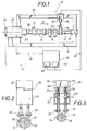
- Figure 1 shows a schematic representation of the device 10 for the exact rotation angle positioning of a shaft 12 which, provided with eccentric members 14, forms, for example, a crankshaft or camshaft.
- the shaft 12 is clamped in a schematically indicated bearing device 16, which has, for example, a point member 18 on one side and a clamping device 20 for the shaft 12 on the other side.
- the clamping device 20 is, for example, a chuck or jaw chuck.
- the clamping device 20 is provided on a drive device 22, which can advantageously be a servo motor.
- a rotary encoder 24 is provided on the drive device 22.
- the device 10 for angular positioning of the shaft 12 has a scanning device 26 which is arranged to be adjustable in the direction of the central longitudinal axis 28 of the shaft 12 if the device 10 is to be suitable for scanning a plurality of eccentric elements 14.
- the bearing device 16 of the device 10 can be designed with a corresponding guide 30.
- the scanning device 26 has two spaced-apart scanning elements 32, which are provided one behind the other in FIG. 1, so that only one of the two scanning elements 32 is visible, while the other scanning element is covered by the visible scanning element.
- the scanning device 26 also has an electronic output 34, which is connected to an electronic control device 36 indicated schematically by a block. This electrically conductive connection is indicated in FIG. 1 by the arrow line 38.
- the electrical control device 36 is designed with an NC circuit 40 and with a PLC circuit 42, the mode of operation of which is explained in more detail below in connection with FIGS. 9 and 10.
- the NC circuit 40 and the PLC circuit 42 are connected in parallel to one another.
- the NC circuit 40 is electrically connected to the encoder 24, which is indicated by the arrow line 44.
- the arrow line 46 indicates the electrically conductive connection between the electronic control device 36 and the drive device 22.
- the control device 36 is - as is also explained in more detail below in connection with FIGS. 9 and 10 - provided for switching the drive device 22 between at least one rapid speed and a measuring speed that is at least one rapid speed compared to this.
- FIG. 2 illustrates the two spaced-apart sensing elements 32, which protrude from a housing 48 of the scanning device 26 in the same direction, and which, in the working or sensing position of the scanning device 26, from the corresponding eccentric 14 of the shaft rotating about its central longitudinal axis 28 12 can be activated at different times.
- the rotation of the shaft 12 about its longitudinal axis 28 is indicated in FIG. 2 by an arrow 50.
- the right-hand feeler element 32 (FIG. 2) is activated first and then the left-hand feeler element 32 is shifted in time.
- the shift in time between the two activations depends on the speed of the shaft 12, on the shape of the eccentric 14 and on the Wave 12 dependent.
- the reference number 34 also designates the electronic output of the scanning device 26 in FIG.
- FIG. 3 a design of the scanning device 26 is indicated, in which the two scanning elements 32, which protrude from the housing 48 of the scanning device 26 in the same direction and are spaced apart, are designed as electrodes.
- the two electrodes 32 are of course electrically insulated from the housing 48 and contacted with the two poles 52 of a voltage source.
- the sensing elements 32 are resiliently mounted in the housing 48 of the scanning device 26 by means of spring elements 54.
- the eccentric 14 results in a short circuit of the two electrodes, which means that the voltage at the output 34 of the scanning device 26 assumes a different value than if only one of the sensing elements 32 is in contact with the corresponding eccentric 14, or if none of the sensing elements 32 is in contact with the corresponding eccentric 14.
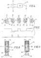
- FIG. 4 indicates optical sensing elements 32 which are designed as light barriers 58 known per se.
- the light barriers 58 are interconnected with an electronic circuit 60, which is only indicated as a block in FIG.
- the electronic circuit 60 has a pulse output which forms the output 34 of the scanning device 26.
- the output 34 is in turn connected to an electronic control device 36 (see FIG. 1), which is not shown in FIG. 4.
- FIG. 5 shows the two spaced-apart light barriers 58 and the shaft 12 with eccentric 14 rotating about its central longitudinal axis 28 in the direction of arrow 50, the two light barriers 58 being arranged at a suitable distance from the shaft 12 to the central longitudinal axis 28 at least approximately in parallel are.
- five different rotational angle positions of the shaft 12 are drawn in the upper row, which are taken in succession during a rotation of the shaft 12 in the direction of the arrow 50.
- the two light barriers 58 either remain completely uncovered, or one (left) light barrier 58 is covered, or the eccentric is located in the middle between the two light barriers 58.
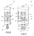
- FIGS 6 and 7 show a preferred embodiment of the scanning device 26 in a side and front view, the housing 48 being drawn partially cut away.
- the two sensing elements 32 are designed as mechanical pushbuttons, which are elastically resiliently supported by spring elements 54 in the housing 48.
- Each button or each sensing element 32 is formed with a switch contact 62 of an electrical switch 64, which is electrically conductively connected to the electronic output 34 of the scanning device 26 by means of a connecting line 66.
- the scanning device 26 or the two scanning elements 32 of the scanning device 26 are formed with reference elements 68, which are provided for the autonomous comparison of the scanning device 26.
- Reference number 12 also designates the shaft formed with at least one eccentric element 14 in FIG. 7.
- the functioning of the scanning device 26 according to FIGS. 6 and 7 is explained below in connection with FIGS. 8, 9 and 10, FIG. 8 showing a schematic illustration of the scanning device 26 according to FIGS. 6 and 7.
- the pushbuttons 32 protrude from the schematically indicated housing 48 of the scanning device 26 and are designed to be elastically resilient by means of the spring elements 54.
- Each of the two sensing elements 32 is provided with a switch contact 62 of the electrical switch 64.
- the reference organ 68 is also indicated schematically in FIG. 8.
- FIG. 11 shows an alternative construction of the scanning device 26 according to FIG. 8. The difference is that instead of the switch contact 62 of an electrical switch 64, a scanning bar 78 is only provided on the one button 32, while the other button 32 has a non-contact displacement sensor 76, which is connected to the electrical output 34 of the scanning device 26 in an electrically conductive manner is.
- the drive device 22 is activated in such a way that the shaft 12 is driven at a rapid speed n1.
- the shaft 12 is then driven at a rapid speed n1 until the eccentric element 14 comes into contact with the right-hand feeler element 32 in a counterclockwise rotation, as indicated by the arrow 50.
- a pulse 70 is generated at the pulse output.
- the output of the PLC circuit 42 is switched to the other level, which is indicated in FIG. 9 by the switching stage 72, and with the aid of the control device 36 the drive device 22 is switched from the rapid speed n1 to a measuring speed n2 which is less than that Rapid speed n1. In this way, an exact rotation angle positioning of the shaft 12 is possible in a very time-saving manner.
- the shaft 12 is driven with the measuring speed n2 in the counterclockwise direction until the eccentric element 14 is located exactly between the two sensing elements 32.
- a second pulse 74 is generated, the output of the PLC circuit 42 (see FIG. 1) is reset to the initial voltage state and the drive device 22 is switched off, so that the speed n becomes zero.
- the measuring speed is also designated n2 in this figure.
Landscapes
- Physics & Mathematics (AREA)
- General Physics & Mathematics (AREA)
- Engineering & Computer Science (AREA)
- Mechanical Engineering (AREA)
- Length Measuring Devices With Unspecified Measuring Means (AREA)
- Measurement Of Length, Angles, Or The Like Using Electric Or Magnetic Means (AREA)
Applications Claiming Priority (2)
| Application Number | Priority Date | Filing Date | Title |
|---|---|---|---|
| DE4035189 | 1990-11-06 | ||
| DE19904035189 DE4035189A1 (de) | 1990-11-06 | 1990-11-06 | Vorrichtung zur drehwinkelpositionierung einer mit exzenterorganen versehenen welle |
Publications (1)
| Publication Number | Publication Date |
|---|---|
| EP0484834A1 true EP0484834A1 (fr) | 1992-05-13 |
Family
ID=6417702
Family Applications (1)
| Application Number | Title | Priority Date | Filing Date |
|---|---|---|---|
| EP91118674A Withdrawn EP0484834A1 (fr) | 1990-11-06 | 1991-11-01 | Positionnement angulaire de broches |
Country Status (2)
| Country | Link |
|---|---|
| EP (1) | EP0484834A1 (fr) |
| DE (1) | DE4035189A1 (fr) |
Cited By (5)
| Publication number | Priority date | Publication date | Assignee | Title |
|---|---|---|---|---|
| FR2820069A1 (fr) * | 2001-01-29 | 2002-08-02 | Atamec C Fourneyron | Dispositif de referencement de la position angulaire d'un vilebrequin, ou equivalent, a au moins un poste d'usinage ou de traitement |
| US7367756B2 (en) * | 2002-10-28 | 2008-05-06 | Horkos Corp | Work phase determination method for machine tools, and device therefor |
| CN106556645A (zh) * | 2016-11-25 | 2017-04-05 | 长沙理工大学 | 一种实心轴的超声合成孔径聚焦检测装置及成像方法 |
| CN106965011A (zh) * | 2017-05-03 | 2017-07-21 | 重庆天运汽车配件有限公司 | 凸轮轴加工用夹持装置 |
| CN109108819A (zh) * | 2018-08-14 | 2019-01-01 | 全椒县源峰锻造有限公司 | 一种分段固定的凸轮轴抛光用固定装置 |
Citations (5)
| Publication number | Priority date | Publication date | Assignee | Title |
|---|---|---|---|---|
| DE3151613A1 (de) * | 1980-12-29 | 1982-08-12 | Yoshii Kogyo Co., Ltd., Yokohama, Kanagawa | Vorrichtung zum positionieren eines spannfutters fuereine fraes- oder drehmaschine |
| DE3335929A1 (de) * | 1983-10-04 | 1985-04-18 | Klaus 5204 Lohmar Allert | Schleifmaschine |
| DE3838019A1 (de) * | 1987-11-10 | 1989-05-18 | Hiroshi Teramachi | Drehpositioniervorrichtung |
| DE3839030C2 (fr) * | 1988-11-18 | 1991-02-14 | Uwe Dipl.-Ing. 3000 Hannover De Gerstmann | |
| DE3933383A1 (de) * | 1989-10-06 | 1991-04-18 | Hitachi Ltd | Verfahren zum positionieren |
-
1990
- 1990-11-06 DE DE19904035189 patent/DE4035189A1/de not_active Ceased
-
1991
- 1991-11-01 EP EP91118674A patent/EP0484834A1/fr not_active Withdrawn
Patent Citations (5)
| Publication number | Priority date | Publication date | Assignee | Title |
|---|---|---|---|---|
| DE3151613A1 (de) * | 1980-12-29 | 1982-08-12 | Yoshii Kogyo Co., Ltd., Yokohama, Kanagawa | Vorrichtung zum positionieren eines spannfutters fuereine fraes- oder drehmaschine |
| DE3335929A1 (de) * | 1983-10-04 | 1985-04-18 | Klaus 5204 Lohmar Allert | Schleifmaschine |
| DE3838019A1 (de) * | 1987-11-10 | 1989-05-18 | Hiroshi Teramachi | Drehpositioniervorrichtung |
| DE3839030C2 (fr) * | 1988-11-18 | 1991-02-14 | Uwe Dipl.-Ing. 3000 Hannover De Gerstmann | |
| DE3933383A1 (de) * | 1989-10-06 | 1991-04-18 | Hitachi Ltd | Verfahren zum positionieren |
Cited By (7)
| Publication number | Priority date | Publication date | Assignee | Title |
|---|---|---|---|---|
| FR2820069A1 (fr) * | 2001-01-29 | 2002-08-02 | Atamec C Fourneyron | Dispositif de referencement de la position angulaire d'un vilebrequin, ou equivalent, a au moins un poste d'usinage ou de traitement |
| EP1231020A1 (fr) * | 2001-01-29 | 2002-08-14 | Atamec C. Fourneyron | Dispositif de référencement de la position angulaire d'un vilebréquin, ou équivalent, à au moins un poste d'usinage ou de traitement |
| US7367756B2 (en) * | 2002-10-28 | 2008-05-06 | Horkos Corp | Work phase determination method for machine tools, and device therefor |
| CN106556645A (zh) * | 2016-11-25 | 2017-04-05 | 长沙理工大学 | 一种实心轴的超声合成孔径聚焦检测装置及成像方法 |
| CN106965011A (zh) * | 2017-05-03 | 2017-07-21 | 重庆天运汽车配件有限公司 | 凸轮轴加工用夹持装置 |
| CN109108819A (zh) * | 2018-08-14 | 2019-01-01 | 全椒县源峰锻造有限公司 | 一种分段固定的凸轮轴抛光用固定装置 |
| CN109108819B (zh) * | 2018-08-14 | 2020-09-01 | 全椒县源峰锻造有限公司 | 一种分段固定的凸轮轴抛光用固定装置 |
Also Published As
| Publication number | Publication date |
|---|---|
| DE4035189A1 (de) | 1992-05-07 |
Similar Documents
| Publication | Publication Date | Title |
|---|---|---|
| DE3103643C2 (de) | Vorrichtung für die Auswahl oder Korrektur von Informationen bei einer elektronischen Uhr | |
| DE69302817T2 (de) | Fehlertoleranter reluktanzmotor | |
| DE2754732A1 (de) | Automatisches messverfahren fuer eine numerisch gesteuerte werkzeugmaschine und vorrichtung zur durchfuehrung dieses verfahrens | |
| DE102015105867B4 (de) | Rotationswinkelsensor mit Sockel und Rotationsmaschine | |
| DE2911103C2 (de) | Vorrichtung zum Verschwenken der Scheinwerfer eines Kraftfahrzeuges | |
| EP0006160B1 (fr) | Dispositif pour établir un rapport reproductible entre deux éléments mécaniques | |
| DE3602292A1 (de) | Geberanordnung | |
| DE19746115B4 (de) | Uhrwerk | |
| DE3734072A1 (de) | Kettenwirkmaschine mit mittels versatzschrittmotoren verstellbaren legebarren | |
| DE102004019945A1 (de) | Rotationsantriebsgerät | |
| EP1615332A1 (fr) | Procédé de fonctionnement d'un moteur à commutation électronique | |
| EP0484834A1 (fr) | Positionnement angulaire de broches | |
| DE2853505C2 (de) | Vorrichtung zur manuellen Erzeugung elektrischer Impulse | |
| DE69001703T2 (de) | Verfahren und geraet zur herstellung einer nute in einem werkstueck. | |
| DE2817209B1 (de) | Verfahren zur Einstellung der Normierposition bei Schrittabtrieben | |
| EP0407654B1 (fr) | Appareil d'indication et procédé pour la détermination de la position absolute d'une aiquille dans l'appareil | |
| DE4210934C1 (fr) | ||
| DE2237229A1 (de) | Vorrichtung fuer den antrieb von vorschubmotoren bei werkzeugmaschinen | |
| DE2627478A1 (de) | Einrichtung zum zentrieren eines werkstuecks | |
| DE1602771C3 (de) | Positioniereinrichtung an Werkzeugmaschinen | |
| DE19947483B4 (de) | Kraftfahrzeug-Türschloss | |
| DE2242397A1 (de) | Steuereinrichtung fuer schuhbearbeitungsmaschinen | |
| WO1988001045A1 (fr) | Dispositif electro-optique de controle continu de la position relative dans l'espace de deux machines ou parties de machines | |
| DE19605452C2 (de) | Antriebseinrichtung | |
| EP1643205A1 (fr) | Dispositif d'éclairage pour lunette de visée |
Legal Events
| Date | Code | Title | Description |
|---|---|---|---|
| PUAI | Public reference made under article 153(3) epc to a published international application that has entered the european phase |
Free format text: ORIGINAL CODE: 0009012 |
|
| AK | Designated contracting states |
Kind code of ref document: A1 Designated state(s): DE ES FR GB IT SE |
|
| 17P | Request for examination filed |
Effective date: 19920312 |
|
| 17Q | First examination report despatched |
Effective date: 19940301 |
|
| STAA | Information on the status of an ep patent application or granted ep patent |
Free format text: STATUS: THE APPLICATION IS DEEMED TO BE WITHDRAWN |
|
| 18D | Application deemed to be withdrawn |
Effective date: 19940913 |