EP0484868A1 - Rubber sheet forming apparatus - Google Patents
Rubber sheet forming apparatus Download PDFInfo
- Publication number
- EP0484868A1 EP0484868A1 EP91118818A EP91118818A EP0484868A1 EP 0484868 A1 EP0484868 A1 EP 0484868A1 EP 91118818 A EP91118818 A EP 91118818A EP 91118818 A EP91118818 A EP 91118818A EP 0484868 A1 EP0484868 A1 EP 0484868A1
- Authority
- EP
- European Patent Office
- Prior art keywords
- rubber
- main body
- nozzle port
- body block
- head
- Prior art date
- Legal status (The legal status is an assumption and is not a legal conclusion. Google has not performed a legal analysis and makes no representation as to the accuracy of the status listed.)
- Granted
Links
Images




Classifications
-
- B—PERFORMING OPERATIONS; TRANSPORTING
- B29—WORKING OF PLASTICS; WORKING OF SUBSTANCES IN A PLASTIC STATE IN GENERAL
- B29C—SHAPING OR JOINING OF PLASTICS; SHAPING OF MATERIAL IN A PLASTIC STATE, NOT OTHERWISE PROVIDED FOR; AFTER-TREATMENT OF THE SHAPED PRODUCTS, e.g. REPAIRING
- B29C48/00—Extrusion moulding, i.e. expressing the moulding material through a die or nozzle which imparts the desired form; Apparatus therefor
- B29C48/03—Extrusion moulding, i.e. expressing the moulding material through a die or nozzle which imparts the desired form; Apparatus therefor characterised by the shape of the extruded material at extrusion
- B29C48/07—Flat, e.g. panels
- B29C48/08—Flat, e.g. panels flexible, e.g. films
-
- B—PERFORMING OPERATIONS; TRANSPORTING
- B29—WORKING OF PLASTICS; WORKING OF SUBSTANCES IN A PLASTIC STATE IN GENERAL
- B29C—SHAPING OR JOINING OF PLASTICS; SHAPING OF MATERIAL IN A PLASTIC STATE, NOT OTHERWISE PROVIDED FOR; AFTER-TREATMENT OF THE SHAPED PRODUCTS, e.g. REPAIRING
- B29C48/00—Extrusion moulding, i.e. expressing the moulding material through a die or nozzle which imparts the desired form; Apparatus therefor
- B29C48/03—Extrusion moulding, i.e. expressing the moulding material through a die or nozzle which imparts the desired form; Apparatus therefor characterised by the shape of the extruded material at extrusion
- B29C48/07—Flat, e.g. panels
-
- B—PERFORMING OPERATIONS; TRANSPORTING
- B29—WORKING OF PLASTICS; WORKING OF SUBSTANCES IN A PLASTIC STATE IN GENERAL
- B29C—SHAPING OR JOINING OF PLASTICS; SHAPING OF MATERIAL IN A PLASTIC STATE, NOT OTHERWISE PROVIDED FOR; AFTER-TREATMENT OF THE SHAPED PRODUCTS, e.g. REPAIRING
- B29C48/00—Extrusion moulding, i.e. expressing the moulding material through a die or nozzle which imparts the desired form; Apparatus therefor
- B29C48/16—Articles comprising two or more components, e.g. co-extruded layers
- B29C48/18—Articles comprising two or more components, e.g. co-extruded layers the components being layers
- B29C48/21—Articles comprising two or more components, e.g. co-extruded layers the components being layers the layers being joined at their surfaces
-
- B—PERFORMING OPERATIONS; TRANSPORTING
- B29—WORKING OF PLASTICS; WORKING OF SUBSTANCES IN A PLASTIC STATE IN GENERAL
- B29C—SHAPING OR JOINING OF PLASTICS; SHAPING OF MATERIAL IN A PLASTIC STATE, NOT OTHERWISE PROVIDED FOR; AFTER-TREATMENT OF THE SHAPED PRODUCTS, e.g. REPAIRING
- B29C48/00—Extrusion moulding, i.e. expressing the moulding material through a die or nozzle which imparts the desired form; Apparatus therefor
- B29C48/16—Articles comprising two or more components, e.g. co-extruded layers
- B29C48/18—Articles comprising two or more components, e.g. co-extruded layers the components being layers
- B29C48/22—Articles comprising two or more components, e.g. co-extruded layers the components being layers with means connecting the layers, e.g. tie layers or undercuts
-
- B—PERFORMING OPERATIONS; TRANSPORTING
- B29—WORKING OF PLASTICS; WORKING OF SUBSTANCES IN A PLASTIC STATE IN GENERAL
- B29C—SHAPING OR JOINING OF PLASTICS; SHAPING OF MATERIAL IN A PLASTIC STATE, NOT OTHERWISE PROVIDED FOR; AFTER-TREATMENT OF THE SHAPED PRODUCTS, e.g. REPAIRING
- B29C48/00—Extrusion moulding, i.e. expressing the moulding material through a die or nozzle which imparts the desired form; Apparatus therefor
- B29C48/25—Component parts, details or accessories; Auxiliary operations
- B29C48/30—Extrusion nozzles or dies
- B29C48/35—Extrusion nozzles or dies with rollers
-
- B—PERFORMING OPERATIONS; TRANSPORTING
- B29—WORKING OF PLASTICS; WORKING OF SUBSTANCES IN A PLASTIC STATE IN GENERAL
- B29C—SHAPING OR JOINING OF PLASTICS; SHAPING OF MATERIAL IN A PLASTIC STATE, NOT OTHERWISE PROVIDED FOR; AFTER-TREATMENT OF THE SHAPED PRODUCTS, e.g. REPAIRING
- B29C48/00—Extrusion moulding, i.e. expressing the moulding material through a die or nozzle which imparts the desired form; Apparatus therefor
- B29C48/25—Component parts, details or accessories; Auxiliary operations
- B29C48/36—Means for plasticising or homogenising the moulding material or forcing it through the nozzle or die
- B29C48/49—Means for plasticising or homogenising the moulding material or forcing it through the nozzle or die using two or more extruders to feed one die or nozzle
-
- B—PERFORMING OPERATIONS; TRANSPORTING
- B29—WORKING OF PLASTICS; WORKING OF SUBSTANCES IN A PLASTIC STATE IN GENERAL
- B29C—SHAPING OR JOINING OF PLASTICS; SHAPING OF MATERIAL IN A PLASTIC STATE, NOT OTHERWISE PROVIDED FOR; AFTER-TREATMENT OF THE SHAPED PRODUCTS, e.g. REPAIRING
- B29C48/00—Extrusion moulding, i.e. expressing the moulding material through a die or nozzle which imparts the desired form; Apparatus therefor
- B29C48/16—Articles comprising two or more components, e.g. co-extruded layers
- B29C48/18—Articles comprising two or more components, e.g. co-extruded layers the components being layers
- B29C48/19—Articles comprising two or more components, e.g. co-extruded layers the components being layers the layers being joined at their edges
-
- B—PERFORMING OPERATIONS; TRANSPORTING
- B29—WORKING OF PLASTICS; WORKING OF SUBSTANCES IN A PLASTIC STATE IN GENERAL
- B29K—INDEXING SCHEME ASSOCIATED WITH SUBCLASSES B29B, B29C OR B29D, RELATING TO MOULDING MATERIALS OR TO MATERIALS FOR MOULDS, REINFORCEMENTS, FILLERS OR PREFORMED PARTS, e.g. INSERTS
- B29K2021/00—Use of unspecified rubbers as moulding material
-
- B—PERFORMING OPERATIONS; TRANSPORTING
- B29—WORKING OF PLASTICS; WORKING OF SUBSTANCES IN A PLASTIC STATE IN GENERAL
- B29L—INDEXING SCHEME ASSOCIATED WITH SUBCLASS B29C, RELATING TO PARTICULAR ARTICLES
- B29L2030/00—Pneumatic or solid tyres or parts thereof
Definitions
- the present invention relates to a rubber sheet forming apparatus capable of adhering rubber sheets formed by overlaying two rubber materials firmly on the joint surfaces.
- Such complex rubber sheets were hitherto manufactured, as shown in Fig. 11 (a), by individually rolling rubber sheets (b1, b2) by using two single roll machines (a1, a2), and gluing the two rubber sheets to form a complex sheet (c).
- a complex sheet (c) was formed by rolling in upper and lower stages (d, e), and compressing in middle stage (f).
- a rubber sheet forming apparatus comprising a rubber extruder (2) having an upper rubber extruder main body (4), a lower rubber extruder main body (5) arranged at an acute angle with respect to the upper rubber extruder main body (4), a main body block (6) mounting the front ends of the upper and lower rubber extruder main bodies (4, 5) at the rear side thereof, and an upper and a lower heads (9,10) each coupled to the main body block (6) for forming a nozzle port (7), and a roll forming device (3) disposed ahead of the rubber extruder (2) for rolling a rubber extruded from the nozzle port (7).
- the main body block (6) comprises a base part (12) having an upper rubber passage (16) and a lower rubber passage (17) communicating with rubber exits (15A, 15B) of the upper and lower rubber extruder main bodies (4, 5), and a protrusion part (14) projected at the front surface (13) of the base part (12)so as to reduce the thickness toward the forward side and having upper and lower slopes (19A, 19B) on which rubber coming out from the upper and lower rubber passages (16, 17) flow respectively.
- the upper head (9) and lower head (10) are respectively disposed on the main body block (6) so as to close the upper and lower slopes (19A, 19B), form an upper rubber path (21) between the upper slope (19A) and the upper head (9), form an lower rubber path (22) between the lower slope (19B) and the lower head (10), and form the nozzle port (7) communicating with a joining part (23) joining the upper and lower rubber paths (21, 22).
- the roll forming device (3) has an upper roll (51) and a lower roll (52) disposed ahead of the nozzle port (7) and pressing the overlaid rubber extruded from the nozzle port (7).
- the main body block (6) may have a detachable tongue piece (20) for varying the sectional shape of the upper or lower rubber path (21, 22) at the front end of the protrusion part (14).
- the nozzle port is opened to the overlap part of the upper rubber path communicating with the upper rubber extruder main body and the lower rubber path communicating with the lower rubber extruder main body. Therefore, the rubber materials sent out from the upper and lower rubber extruder main bodies are overlaid without being exposed to air, and therefore dust does not deposit on the overlaying surfaces and the adhesion surfaces are not dried before adhesion, so that the both rubber materials are adhered securely. Besides, since the both rubber materials are joined before being discharged from the nozzle port, it is easy to increase the overlapping surface area by forming the joining surfaces in zigzag or undulated form, so that the adhesion strength may be further enhanced. Still more, since the joining precision of the both rubber materials is enhanced, the finishing precision of the rubber sheet composed of complex rubber in a completed form may be also enhanced.
- the rubber sheet forming apparatus of the invention has an organically united and assembled constitution, and is hence capable of forming rubber sheet made of complex rubber excellent in adhesion, at high precision.
- the sectional shape of the upper or lower rubber path may be changed, and hence the adhesion surface may be freely varied, so that increases of adhesion strength and diversification of disposing position of two rubber layers may be realized.
- the rubber sheet forming apparatus 1 has a roll forming device 3 disposed ahead of a rubber extruder 2.
- the rubber extruder 2 comprises an upper rubber extruder main body 4, a lower rubber extruder main body 5 crossing at an acute angle with the upper rubber extruder main body 5, a main body block 6 fixing the front ends of the upper and lower extruder main body 4, 5 at the rear side, and an upper head 9 and lower head 10 disposed on the main body block 6 and forming a nozzle port 7.
- the upper rubber extruder main body 4 is formed, in this embodiment, by inserting a feed screw 31 into the hole part of a tubular outer cylinder. By rotation of the feed screw 31, the rubber material G1 charged into the hole part is kneaded and sent out forward.
- the lower rubber extruder main body 5 is composed same as the upper rubber extruder main body 4.
- the main body block 6 has a base part 12 fixed through a post on a carriage 32 which moves in and out to the roll forming device 3 and having two rear surfaces 11A, 11B capable of fixing the front ends of the upper rubber extruder main body 4 and lower rubber extruder main body 5, and a protrusion part 14 projected to the front surface 13 of the base part 12.
- the protrusion part 14 has an upper slope 19A inclining downward toward the front side on the upper side as shown in Figs. 4, 6, and a lower slope 19B inclining upward toward the front side on the lower side, so that the thickness decreases toward the front side.
- a tongue piece 20 is detachably fitted to the front end of the protrusion part 14.
- the upper head 9 is a block body having a rear surface contacting with the upper part of the front surface 13 of the base part 12 and an upper joint surface 34A contacting with the upper slope 19A of the protrusion 14, and a groove 35 confronting the upper groove 33A is disposed on the upper joint surface 34A.
- the upper part of the upper head 9 is rotatably pinned to the base part 12.
- One end of an expansion tool 36 such as a hydraulic cylinder pivoted to the base part 12 is pivoted to the upper part of the upper head 9, and by expansion and contraction of the expansion tool 36, the upper head 9 may be brought closer to or remoter from the main body block 6.
- the rear surface of the upper head 9 contacts with the front surface 13 of the base part 12, and the upper joint surface 34A contacts with the upper slope 19A of the protrusion part 14, and by the upper groove 33A and the groove 35, an upper rubber path 21 leading to the upper rubber passage 16 is formed.
- the lower head 10 is formed symmetrically with the upper head 9 in vertical direction, and by the extension of the expansion tool 36, its rear surface contacts with the front surface 13 of the base part 12, and the lower joint surface 34B contacts with the lower slope 19B, and the lower rubber path 22 is formed by the lower groove 33B and the groove 35.
- the upper and lower rubber paths 21, 22 meet at the front end of the rubber extruder 2, and an overlap part 23 is formed.
- a nozzle port 7 formed by the upper and lower heads 9, 10 is disposed.
- the front end part enclosing the nozzle port 7 of the upper is formed by a pair of nozzle pieces 37, 39 detachably fitted to the upper and lower heads 9, 10.
- the tongue piece 20 is composed as shown in Fig. 7 in this embodiment, that is, plural pieces 45 are projecting forward to the front end of a base part 44 of nearly triangular section having an upper slope 42 and a lower slope 43 inclining at nearly a same angle as the upper and lower slopes 19A, 19B from the upper and lower end of the rear surface 41 contacting with the front end surface of the protrusion part 14.
- the tongue piece 20 is detachably fitted to the projection part 14 by driving a bolt horizontally into a bolt hole 46 drilled in the rear surface 41 from behind the main body block 6.
- the tongue piece 20 is installed as stated above, and the pieces 45 bulge out into the lower rubber path 22. By installing upside down, the pieces 45 may be projected into the upper rubber path 21.
- the upper head 9, main body block 6, and lower head 10 are fixed by a pair of clamp tools 49, 49 capable of holding these three members' sideways.
- the roll forming device 3 is a single roll calender machine, in this embodiment, disposing an upper roll 51 and a lower roll 52 in upper and lower positions, and the gap (g) between the upper and lower rolls 51, 52 forming the rolling entrance is disposed close to the nozzle port 7.
- the rubber extruder 2 When the rubber extruder 2 is mounted on the carrier 32 as this embodiment, prior to rubber sheet forming job, the rubber extruder 2 is moved forward to bring the nozzle port 7 closer to the gap (g), so that the rubber discharged from the nozzle port 7 may be immediately rolled and formed.
- rubber materials G1, G2 are supplied to the upper rubber extruder main body 4 and lower rubber extruder main body 5.
- the rubber material G1 charged into the upper rubber extruder main body 4 is kneaded by the feed screw 31, and reaches the overlap part 23 through the upper rubber passage 16 and upper rubber path 21.
- the rubber material G2 charged into the lower rubber extruder main body 5 is similarly kneaded, and divided into plural lines Gn by the pieces 45 of the tongue piece 20 through the lower rubber passage 17 and lower rubber path 22, thereby reaching the overlap part 23.
- the two rubber materials G1, G2 are overlapped to compose a complex rubber G3, which is discharged from the nozzle port 7 toward the gap (g) of the roll forming device 3.
- the complex rubber G3 is rolled and joined by the upper and lower rolls 51, 52 of the roll forming device 3, and a continuous rubber sheet H composed of two rubber layers is formed as shown in Fig. 8.
- the extrusion sectional shape of one or both rubber materials may be set freely, so that the junction surface may be further reinforced.
- Fig. 9 shows other embodiment of the tongue piece 20.
- the pieces 45, 45 are disposed only at both sides in the widthwise direction, and the formed rubber sheet H is set as shown in Fig. 10, while the upper surface and both side surfaces of one rubber material G2 are covered with the other rubber material G1.
- the roll forming device 3 may be deformed in various forms in the invention, including a calender machine using four rolls, as well as the single roll calender machine.
- the upper rubber path communicating with the upper rubber extruder main body and the lower rubber path communicating with the lower rubber extruder main body meet at the overlap part, so that two rubber materials may be joined without being exposed to fresh air.
- the roll forming device since the roll forming device is located ahead of the nozzle port, two rubber materials may be compressed, and a rubber sheet composed of a complex rubber with a strong adhesion strength and high junction precision may be formed, so that it may be preferably applied in manufacture of belt for belt conveyer, waterproof sheet, liner of tire and others.
Landscapes
- Engineering & Computer Science (AREA)
- Mechanical Engineering (AREA)
- Manufacturing & Machinery (AREA)
- Extrusion Moulding Of Plastics Or The Like (AREA)
- Lining Or Joining Of Plastics Or The Like (AREA)
Abstract
Description
- The present invention relates to a rubber sheet forming apparatus capable of adhering rubber sheets formed by overlaying two rubber materials firmly on the joint surfaces.
- Complex rubber sheets of two rubber layers differing in rubber composition, for example, a hard rubber sheet material and a soft rubber sheet material are widely used.
- Such complex rubber sheets were hitherto manufactured, as shown in Fig. 11 (a), by individually rolling rubber sheets (b1, b2) by using two single roll machines (a1, a2), and gluing the two rubber sheets to form a complex sheet (c).
- Or, as shown in Fig. 11 (b), using a roll Cardan machine (a3) comprising four rolls, a complex sheet (c) was formed by rolling in upper and lower stages (d, e), and compressing in middle stage (f).
- In the above constitution, however, since the rolled rubber materials are exposed to air until compressed, the adhesion strength is lowered due to deposit of dust particles contained in the air or drying of the adhesion surface, and the adhesion surface was often separated.
- To solve a part of the above problems, it was proposed in the Japanese patent publication No. 61-14932 to dispose the nozzles of two extruders closely to each other near the roller periphery, and overlay the two sheets extruded from the nozzles on the roller.
- In this proposal, although the problems of dust deposit and drying of the adhesion surfaces may be solved, the pressing force between sheets is weak, the adhesion is also weak, and the problems are not solved completely.
- Accordingly, it is an object of the present invention to provide a rubber sheet forming apparatus capable of joining rubber sheets made of complex rubber powerfully on the adhesion surface, and enhancing the finishing precision.
- According to one aspect of the present invention, a rubber sheet forming apparatus comprising a rubber extruder (2) having an upper rubber extruder main body (4), a lower rubber extruder main body (5) arranged at an acute angle with respect to the upper rubber extruder main body (4), a main body block (6) mounting the front ends of the upper and lower rubber extruder main bodies (4, 5) at the rear side thereof, and an upper and a lower heads (9,10) each coupled to the main body block (6) for forming a nozzle port (7), and a roll forming device (3) disposed ahead of the rubber extruder (2) for rolling a rubber extruded from the nozzle port (7). The main body block (6) comprises a base part (12) having an upper rubber passage (16) and a lower rubber passage (17) communicating with rubber exits (15A, 15B) of the upper and lower rubber extruder main bodies (4, 5), and a protrusion part (14) projected at the front surface (13) of the base part (12)so as to reduce the thickness toward the forward side and having upper and lower slopes (19A, 19B) on which rubber coming out from the upper and lower rubber passages (16, 17) flow respectively. The upper head (9) and lower head (10) are respectively disposed on the main body block (6) so as to close the upper and lower slopes (19A, 19B), form an upper rubber path (21) between the upper slope (19A) and the upper head (9), form an lower rubber path (22) between the lower slope (19B) and the lower head (10), and form the nozzle port (7) communicating with a joining part (23) joining the upper and lower rubber paths (21, 22). And the roll forming device (3) has an upper roll (51) and a lower roll (52) disposed ahead of the nozzle port (7) and pressing the overlaid rubber extruded from the nozzle port (7). The main body block (6) may have a detachable tongue piece (20) for varying the sectional shape of the upper or lower rubber path (21, 22) at the front end of the protrusion part (14).
- As mentioned above, the nozzle port is opened to the overlap part of the upper rubber path communicating with the upper rubber extruder main body and the lower rubber path communicating with the lower rubber extruder main body. Therefore, the rubber materials sent out from the upper and lower rubber extruder main bodies are overlaid without being exposed to air, and therefore dust does not deposit on the overlaying surfaces and the adhesion surfaces are not dried before adhesion, so that the both rubber materials are adhered securely. Besides, since the both rubber materials are joined before being discharged from the nozzle port, it is easy to increase the overlapping surface area by forming the joining surfaces in zigzag or undulated form, so that the adhesion strength may be further enhanced. Still more, since the joining precision of the both rubber materials is enhanced, the finishing precision of the rubber sheet composed of complex rubber in a completed form may be also enhanced.
- In addition, since the roll forming device is disposed ahead of the nozzle port, the both rubber materials are compressed, and the adhesion strength is further improved.
- Thus, the rubber sheet forming apparatus of the invention has an organically united and assembled constitution, and is hence capable of forming rubber sheet made of complex rubber excellent in adhesion, at high precision.
- Meanwhile, when a tongue piece is detachably fitted to the front end of the protrusion part of the main body block, by properly selecting the shape of the tongue piece, the sectional shape of the upper or lower rubber path may be changed, and hence the adhesion surface may be freely varied, so that increases of adhesion strength and diversification of disposing position of two rubber layers may be realized.
- An embodiment of the present invention will now be described by way of example, referring the attached drawings, in which;
- Fig. 1 is a front view showing an embodiment of the invention.
- Fig. 2 is a plan view thereof.
- Fig. 3 is a front side view thereof.
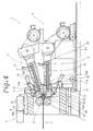
- Fig. 4 is a partial sectional front view showing essential parts together with action.
- Fig. 5 is a plan view thereof.
- Fig. 6 is a sectional view magnifying the overlap part.
- Fig. 7 is a perspective view showing a tongue piece.
- Fig. 8 is a perspective view showing a rubber sheet formed by using the apparatus of the invention.
- Fig. 9 is a perspective view showing other example of tongue piece.
- Fig. 10 is a perspective view showing other example of rubber sheet.
- Fig. 11(a), (b) are front views schematically showing the prior art.
- In Fig. 1 to Fig. 8, the rubber
sheet forming apparatus 1 has aroll forming device 3 disposed ahead of arubber extruder 2. Therubber extruder 2 comprises an upper rubber extrudermain body 4, a lower rubber extrudermain body 5 crossing at an acute angle with the upper rubber extrudermain body 5, amain body block 6 fixing the front ends of the upper and lower extrudermain body upper head 9 andlower head 10 disposed on themain body block 6 and forming anozzle port 7. - The upper rubber extruder
main body 4 is formed, in this embodiment, by inserting afeed screw 31 into the hole part of a tubular outer cylinder. By rotation of thefeed screw 31, the rubber material G1 charged into the hole part is kneaded and sent out forward. - The lower rubber extruder
main body 5 is composed same as the upper rubber extrudermain body 4. - The
main body block 6 has abase part 12 fixed through a post on acarriage 32 which moves in and out to theroll forming device 3 and having tworear surfaces main body 4 and lower rubber extrudermain body 5, and aprotrusion part 14 projected to thefront surface 13 of thebase part 12. - In the
base part 12, are formed anupper rubber passage 16 and alower rubber passage 17 communicating respectively withrubber exits 15A, 15B of the upper and lower extrudermain bodies - The
protrusion part 14 has anupper slope 19A inclining downward toward the front side on the upper side as shown in Figs. 4, 6, and alower slope 19B inclining upward toward the front side on the lower side, so that the thickness decreases toward the front side. In this embodiment, atongue piece 20 is detachably fitted to the front end of theprotrusion part 14. - On the
upper slope 19A andlower slope 19B, are formed anupper groove 33A and alower groove 33B communicating with theupper rubber passage 16 andlower rubber passage 17. - The
upper head 9 is a block body having a rear surface contacting with the upper part of thefront surface 13 of thebase part 12 and anupper joint surface 34A contacting with theupper slope 19A of theprotrusion 14, and agroove 35 confronting theupper groove 33A is disposed on theupper joint surface 34A. - The upper part of the
upper head 9 is rotatably pinned to thebase part 12. One end of anexpansion tool 36 such as a hydraulic cylinder pivoted to thebase part 12 is pivoted to the upper part of theupper head 9, and by expansion and contraction of theexpansion tool 36, theupper head 9 may be brought closer to or remoter from themain body block 6. - By the approach of the
main body block 6, the rear surface of theupper head 9 contacts with thefront surface 13 of thebase part 12, and theupper joint surface 34A contacts with theupper slope 19A of theprotrusion part 14, and by theupper groove 33A and thegroove 35, anupper rubber path 21 leading to theupper rubber passage 16 is formed. - The
lower head 10 is formed symmetrically with theupper head 9 in vertical direction, and by the extension of theexpansion tool 36, its rear surface contacts with thefront surface 13 of thebase part 12, and thelower joint surface 34B contacts with thelower slope 19B, and thelower rubber path 22 is formed by thelower groove 33B and thegroove 35. - The upper and
lower rubber paths rubber extruder 2, and anoverlap part 23 is formed. At the front end of theoverlap part 23, anozzle port 7 formed by the upper andlower heads - In this embodiment, the front end part enclosing the
nozzle port 7 of the upper is formed by a pair ofnozzle pieces lower heads - The
tongue piece 20 is composed as shown in Fig. 7 in this embodiment, that is,plural pieces 45 are projecting forward to the front end of abase part 44 of nearly triangular section having anupper slope 42 and alower slope 43 inclining at nearly a same angle as the upper andlower slopes protrusion part 14. - The
tongue piece 20 is detachably fitted to theprojection part 14 by driving a bolt horizontally into abolt hole 46 drilled in the rear surface 41 from behind themain body block 6. - The
tongue piece 20 is installed as stated above, and thepieces 45 bulge out into thelower rubber path 22. By installing upside down, thepieces 45 may be projected into theupper rubber path 21. - The
upper head 9,main body block 6, andlower head 10 are fixed by a pair ofclamp tools - The
roll forming device 3 is a single roll calender machine, in this embodiment, disposing anupper roll 51 and alower roll 52 in upper and lower positions, and the gap (g) between the upper andlower rolls nozzle port 7. - When the
rubber extruder 2 is mounted on thecarrier 32 as this embodiment, prior to rubber sheet forming job, therubber extruder 2 is moved forward to bring thenozzle port 7 closer to the gap (g), so that the rubber discharged from thenozzle port 7 may be immediately rolled and formed. - In this way, rubber materials G1, G2 are supplied to the upper rubber extruder
main body 4 and lower rubber extrudermain body 5. - The rubber material G1 charged into the upper rubber extruder
main body 4 is kneaded by thefeed screw 31, and reaches theoverlap part 23 through theupper rubber passage 16 andupper rubber path 21. - The rubber material G2 charged into the lower rubber extruder
main body 5 is similarly kneaded, and divided into plural lines Gn by thepieces 45 of thetongue piece 20 through thelower rubber passage 17 andlower rubber path 22, thereby reaching theoverlap part 23. - At the
overlap part 23, the two rubber materials G1, G2 are overlapped to compose a complex rubber G3, which is discharged from thenozzle port 7 toward the gap (g) of theroll forming device 3. - The complex rubber G3 is rolled and joined by the upper and
lower rolls roll forming device 3, and a continuous rubber sheet H composed of two rubber layers is formed as shown in Fig. 8. - Since the two rubber materials G1, G2 are thus joined at the
overlap part 23, the joint surfaces are not exposed to air, and the overlapped two rubber materials G1, G2 are compressed by theroll forming device 3, so that a firm bond is achieved. - When the
tongue piece 20 having thepieces 45 is used as this embodiment, the extrusion sectional shape of one or both rubber materials may be set freely, so that the junction surface may be further reinforced. - Fig. 9 shows other embodiment of the
tongue piece 20. In this case, thepieces - By exchanging the upper and
lower heads grooves - The
roll forming device 3 may be deformed in various forms in the invention, including a calender machine using four rolls, as well as the single roll calender machine. - As previously described, in the rubber sheet forming apparatus according to the present invention, the upper rubber path communicating with the upper rubber extruder main body and the lower rubber path communicating with the lower rubber extruder main body meet at the overlap part, so that two rubber materials may be joined without being exposed to fresh air.
- Besides, since the roll forming device is located ahead of the nozzle port, two rubber materials may be compressed, and a rubber sheet composed of a complex rubber with a strong adhesion strength and high junction precision may be formed, so that it may be preferably applied in manufacture of belt for belt conveyer, waterproof sheet, liner of tire and others.
Claims (2)
- A rubber sheet forming apparatus (1) comprising
a rubber extruder (2) having an upper rubber extruder main body (4), a lower rubber extruder main body (5) arranged at an acute angle with respect to the upper rubber extruder main body (4), a main body block (6) mounting the front ends of the upper and lower rubber extruder main bodies (4, 5) at the rear side thereof, and an upper and a lower heads (9,10) each coupled to the main body block (6) for forming a nozzle port (7), and
a roll forming device (3) disposed ahead of the rubber extruder (2) for rolling a rubber extruded from the nozzle port (7), wherein ;
said main body block (6) comprises a base part (12) having an upper rubber passage (16) and a lower rubber passage (17) communicating with rubber exits (15A, 15B) of the upper and lower rubber extruder main bodies (4, 5), and
a protrusion part (14) projected at the front surface (13) of the base part (12)so as to reduce the thickness toward the forward side and having upper and lower slopes (19A, 19B) on which rubber coming out from the upper and lower rubber passages (16, 17) flow respectively;
said upper head (9) and lower head (10) are respectively disposed on the main body block (6) so as to close the upper and lower slopes (19A, 19B), form an upper rubber path (21) between the upper slope (19A) and the upper head (9), form an lower rubber path (22) between the lower slope (19B) and the lower head (10), and form the nozzle port (7) communicating with a joining part (23) joining the upper and lower rubber paths (21, 22); and
said roll forming device (3) has an upper roll (51) and a lower roll (52) disposed ahead of the nozzle port (7) and pressing the overlaid rubber extruded from the nozzle port (7). - A rubber sheet forming apparatus according to claim 1, wherein the main body block (6) has a detachable tongue piece (20) for varying the sectional shape of the upper or lower rubber path (21, 22) at the front end of the protrusion part (14).
Applications Claiming Priority (2)
| Application Number | Priority Date | Filing Date | Title |
|---|---|---|---|
| JP2305676A JP3040154B2 (en) | 1990-11-09 | 1990-11-09 | Rubber sheet forming equipment |
| JP305676/90 | 1990-11-09 |
Publications (2)
| Publication Number | Publication Date |
|---|---|
| EP0484868A1 true EP0484868A1 (en) | 1992-05-13 |
| EP0484868B1 EP0484868B1 (en) | 1995-06-07 |
Family
ID=17948014
Family Applications (1)
| Application Number | Title | Priority Date | Filing Date |
|---|---|---|---|
| EP91118818A Expired - Lifetime EP0484868B1 (en) | 1990-11-09 | 1991-11-05 | Rubber sheet forming apparatus |
Country Status (3)
| Country | Link |
|---|---|
| EP (1) | EP0484868B1 (en) |
| JP (1) | JP3040154B2 (en) |
| DE (1) | DE69110246T2 (en) |
Cited By (7)
| Publication number | Priority date | Publication date | Assignee | Title |
|---|---|---|---|---|
| FR2700291A1 (en) * | 1993-01-08 | 1994-07-13 | Michelin & Cie | Extrusion apparatus and extrusion method for raw rubber mixtures. |
| WO1999043506A1 (en) * | 1998-02-26 | 1999-09-02 | Compagnie Generale Des Etablissements Michelin - Michelin & Cie | Electrically conductive tyre and apparatus for extruding sections made conductive |
| US6951233B1 (en) | 1998-02-26 | 2005-10-04 | Compagnie Generale Des Etablissements Michelin-Michelin & Cie | Electrically conductive tire and apparatus and process for extruding elements which have been made conductive |
| ITUB20154739A1 (en) * | 2015-10-19 | 2017-04-19 | Simplas Spa | EXTRUSION CONTACT HEAD |
| CN112192823A (en) * | 2020-09-17 | 2021-01-08 | 江苏亨通光电股份有限公司 | Double-heterochromatic strip sheath and extrusion die thereof |
| US20230405947A1 (en) * | 2020-10-20 | 2023-12-21 | Reliefed Ab | An extrusion and/or pultrusion device and method |
| US20240355998A1 (en) * | 2021-08-31 | 2024-10-24 | Reliefed Ab | Device and method for producing electrodes for electrochemical reaction |
Families Citing this family (3)
| Publication number | Priority date | Publication date | Assignee | Title |
|---|---|---|---|---|
| DE102005020432B4 (en) * | 2005-04-29 | 2009-09-03 | Troester Gmbh & Co. Kg | Device for producing a profile |
| US10272655B2 (en) * | 2012-10-02 | 2019-04-30 | 3M Innovative Properties Company | Film with alternating stripes and strands and apparatus and method for making the same |
| DE102016121262B3 (en) * | 2016-11-07 | 2018-02-22 | Troester Gmbh & Co. Kg | extrusion device |
Citations (6)
| Publication number | Priority date | Publication date | Assignee | Title |
|---|---|---|---|---|
| US1356891A (en) * | 1916-02-09 | 1920-10-26 | Morgan & Wright | Apparatus for manufacturing solid tires |
| US1603813A (en) * | 1924-11-08 | 1926-10-19 | Stein Jacob | Apparatus for making striped rubber sheeting |
| US2382177A (en) * | 1941-10-15 | 1945-08-14 | Goodrich Co B F | Apparatus for making composite strips |
| US3443277A (en) * | 1964-11-27 | 1969-05-13 | Shell Oil Co | Apparatus for producing a laminate having mechanically interlocking layers |
| US4137027A (en) * | 1976-05-18 | 1979-01-30 | Karl-Heinz Schmidt | Extruderhead |
| DE3521643C1 (en) * | 1985-06-15 | 1986-07-03 | Hermann Berstorff Maschinenbau Gmbh, 3000 Hannover | Hinged extrusion head for the production of rubber or plastic flat profiles |
-
1990
- 1990-11-09 JP JP2305676A patent/JP3040154B2/en not_active Expired - Lifetime
-
1991
- 1991-11-05 EP EP91118818A patent/EP0484868B1/en not_active Expired - Lifetime
- 1991-11-05 DE DE69110246T patent/DE69110246T2/en not_active Expired - Lifetime
Patent Citations (6)
| Publication number | Priority date | Publication date | Assignee | Title |
|---|---|---|---|---|
| US1356891A (en) * | 1916-02-09 | 1920-10-26 | Morgan & Wright | Apparatus for manufacturing solid tires |
| US1603813A (en) * | 1924-11-08 | 1926-10-19 | Stein Jacob | Apparatus for making striped rubber sheeting |
| US2382177A (en) * | 1941-10-15 | 1945-08-14 | Goodrich Co B F | Apparatus for making composite strips |
| US3443277A (en) * | 1964-11-27 | 1969-05-13 | Shell Oil Co | Apparatus for producing a laminate having mechanically interlocking layers |
| US4137027A (en) * | 1976-05-18 | 1979-01-30 | Karl-Heinz Schmidt | Extruderhead |
| DE3521643C1 (en) * | 1985-06-15 | 1986-07-03 | Hermann Berstorff Maschinenbau Gmbh, 3000 Hannover | Hinged extrusion head for the production of rubber or plastic flat profiles |
Cited By (12)
| Publication number | Priority date | Publication date | Assignee | Title |
|---|---|---|---|---|
| FR2700291A1 (en) * | 1993-01-08 | 1994-07-13 | Michelin & Cie | Extrusion apparatus and extrusion method for raw rubber mixtures. |
| EP0609550A1 (en) * | 1993-01-08 | 1994-08-10 | Compagnie Generale Des Etablissements Michelin-Michelin & Cie | Apparatus and process for extrusion of raw rubber mixtures |
| US5453238A (en) * | 1993-01-08 | 1995-09-26 | Compagnie Generale Des Etablissements Michelin - Michelin & Cie | Extrusion apparatus and method of extrusion for raw rubber mixes |
| WO1999043506A1 (en) * | 1998-02-26 | 1999-09-02 | Compagnie Generale Des Etablissements Michelin - Michelin & Cie | Electrically conductive tyre and apparatus for extruding sections made conductive |
| EP1095798A1 (en) * | 1998-02-26 | 2001-05-02 | Compagnie Générale des Etablissements MICHELIN-MICHELIN & CIE | Apparatus for extruding sections made conductive |
| US6951233B1 (en) | 1998-02-26 | 2005-10-04 | Compagnie Generale Des Etablissements Michelin-Michelin & Cie | Electrically conductive tire and apparatus and process for extruding elements which have been made conductive |
| ITUB20154739A1 (en) * | 2015-10-19 | 2017-04-19 | Simplas Spa | EXTRUSION CONTACT HEAD |
| CN112192823A (en) * | 2020-09-17 | 2021-01-08 | 江苏亨通光电股份有限公司 | Double-heterochromatic strip sheath and extrusion die thereof |
| US20230405947A1 (en) * | 2020-10-20 | 2023-12-21 | Reliefed Ab | An extrusion and/or pultrusion device and method |
| US12377618B2 (en) * | 2020-10-20 | 2025-08-05 | Reliefed Ab | Extrusion and/or pultrusion device and method |
| US20240355998A1 (en) * | 2021-08-31 | 2024-10-24 | Reliefed Ab | Device and method for producing electrodes for electrochemical reaction |
| US12370734B2 (en) * | 2021-08-31 | 2025-07-29 | Reliefed Ab | Device and method for producing electrodes for electrochemical reaction |
Also Published As
| Publication number | Publication date |
|---|---|
| JPH04176626A (en) | 1992-06-24 |
| DE69110246T2 (en) | 1995-10-12 |
| JP3040154B2 (en) | 2000-05-08 |
| EP0484868B1 (en) | 1995-06-07 |
| DE69110246D1 (en) | 1995-07-13 |
Similar Documents
| Publication | Publication Date | Title |
|---|---|---|
| EP0484868B1 (en) | Rubber sheet forming apparatus | |
| US4526528A (en) | Apparatus for forming a co-extrusion from extruded strips | |
| CA2006676C (en) | Process and mold for producing a multilayer molded article | |
| EP0580073B1 (en) | Method and apparatus for manufacturing a material-backed engaging member for surface fastener | |
| US5352397A (en) | Process for producing multilayer molded article including folding of a skin material over a back of a resin material | |
| CA1255576A (en) | Method and apparatus for making a surface-lined article | |
| FI64107B (en) | TILLSLUTNINGSREMSA SAMT FOERFARANDE FOER FRAMSTAELLNING AV MATERIAL FOER FRAMSTAELLNING AV AOTERTILLSLUTBARA PAOSAR | |
| US5928679A (en) | Elastomeric extruding apparatus | |
| US5372168A (en) | Thin plate cutting/joining apparatus | |
| CA2422670A1 (en) | Tape for flying splice, method of use, and method of manufacture | |
| KR19990044117A (en) | Methods and apparatuses for joining two pieces of cloth, such as fabrics, and articles such as apparel articles obtained thereby | |
| ATE290950T1 (en) | METHOD FOR JOINING FILM, WIDE FILM PRODUCED BY THIS METHOD, AND AGRICULTURAL COVERING MATERIAL FROM SUCH WIDE FILM | |
| US5242290A (en) | Extrusion forming apparatus | |
| CA1261580A (en) | Extrusion apparatus and method | |
| DE69805681D1 (en) | Multiaxial papermaker press felt with seam | |
| EP0484869B1 (en) | Extrusion forming apparatus | |
| JPS5833084B2 (en) | Method and device for joining individual boards laminated with foamed synthetic resin | |
| KR102750298B1 (en) | 3D printing system and method using recycled milled fiber | |
| JP2931036B2 (en) | Sealing material and molding method and apparatus therefor | |
| EP0683030A3 (en) | Deep-drawn article, deep-drawing process and deep-drawing apparatus for producing said article | |
| KR950001091B1 (en) | Connecting method of roll plate | |
| JP4472455B2 (en) | Mold for simultaneous injection molding decoration, sheet feeding device, and method for manufacturing injection molding simultaneous decoration | |
| JPS60899B2 (en) | Die for extrusion molding of different synthetic resins | |
| JP3143692B2 (en) | Coating equipment | |
| GB2318082A (en) | Method and apparatus for joining rubbery fabric |
Legal Events
| Date | Code | Title | Description |
|---|---|---|---|
| PUAI | Public reference made under article 153(3) epc to a published international application that has entered the european phase |
Free format text: ORIGINAL CODE: 0009012 |
|
| AK | Designated contracting states |
Kind code of ref document: A1 Designated state(s): DE FR GB IT |
|
| 17P | Request for examination filed |
Effective date: 19921104 |
|
| 17Q | First examination report despatched |
Effective date: 19931129 |
|
| GRAA | (expected) grant |
Free format text: ORIGINAL CODE: 0009210 |
|
| AK | Designated contracting states |
Kind code of ref document: B1 Designated state(s): DE FR GB IT |
|
| ET | Fr: translation filed | ||
| REF | Corresponds to: |
Ref document number: 69110246 Country of ref document: DE Date of ref document: 19950713 |
|
| ITF | It: translation for a ep patent filed | ||
| PLBE | No opposition filed within time limit |
Free format text: ORIGINAL CODE: 0009261 |
|
| STAA | Information on the status of an ep patent application or granted ep patent |
Free format text: STATUS: NO OPPOSITION FILED WITHIN TIME LIMIT |
|
| 26N | No opposition filed | ||
| REG | Reference to a national code |
Ref country code: GB Ref legal event code: IF02 |
|
| PGFP | Annual fee paid to national office [announced via postgrant information from national office to epo] |
Ref country code: IT Payment date: 20061130 Year of fee payment: 16 |
|
| PG25 | Lapsed in a contracting state [announced via postgrant information from national office to epo] |
Ref country code: IT Free format text: LAPSE BECAUSE OF NON-PAYMENT OF DUE FEES Effective date: 20071105 |
|
| PGFP | Annual fee paid to national office [announced via postgrant information from national office to epo] |
Ref country code: FR Payment date: 20101122 Year of fee payment: 20 |
|
| PGFP | Annual fee paid to national office [announced via postgrant information from national office to epo] |
Ref country code: GB Payment date: 20101119 Year of fee payment: 20 |
|
| PGFP | Annual fee paid to national office [announced via postgrant information from national office to epo] |
Ref country code: DE Payment date: 20110113 Year of fee payment: 20 |
|
| REG | Reference to a national code |
Ref country code: DE Ref legal event code: R071 Ref document number: 69110246 Country of ref document: DE |
|
| REG | Reference to a national code |
Ref country code: DE Ref legal event code: R071 Ref document number: 69110246 Country of ref document: DE |
|
| REG | Reference to a national code |
Ref country code: GB Ref legal event code: PE20 Expiry date: 20111104 |
|
| PG25 | Lapsed in a contracting state [announced via postgrant information from national office to epo] |
Ref country code: GB Free format text: LAPSE BECAUSE OF EXPIRATION OF PROTECTION Effective date: 20111104 |
|
| PG25 | Lapsed in a contracting state [announced via postgrant information from national office to epo] |
Ref country code: DE Free format text: LAPSE BECAUSE OF EXPIRATION OF PROTECTION Effective date: 20111106 |