EP0484884B1 - Verfahren zum Steuern des Aufladedruckes einer Brennkraftmaschine - Google Patents
Verfahren zum Steuern des Aufladedruckes einer Brennkraftmaschine Download PDFInfo
- Publication number
- EP0484884B1 EP0484884B1 EP91118844A EP91118844A EP0484884B1 EP 0484884 B1 EP0484884 B1 EP 0484884B1 EP 91118844 A EP91118844 A EP 91118844A EP 91118844 A EP91118844 A EP 91118844A EP 0484884 B1 EP0484884 B1 EP 0484884B1
- Authority
- EP
- European Patent Office
- Prior art keywords
- value
- supercharge pressure
- compression
- compression ratio
- internal
- Prior art date
- Legal status (The legal status is an assumption and is not a legal conclusion. Google has not performed a legal analysis and makes no representation as to the accuracy of the status listed.)
- Expired - Lifetime
Links
- 238000002485 combustion reaction Methods 0.000 title claims description 14
- 238000000034 method Methods 0.000 title claims description 13
- 238000007906 compression Methods 0.000 claims description 79
- 230000006835 compression Effects 0.000 claims description 41
- 238000004891 communication Methods 0.000 description 6
- 238000010586 diagram Methods 0.000 description 6
- 230000004044 response Effects 0.000 description 3
- 238000007789 sealing Methods 0.000 description 3
- 238000007599 discharging Methods 0.000 description 2
- 230000002093 peripheral effect Effects 0.000 description 2
- 238000011144 upstream manufacturing Methods 0.000 description 2
- 239000000498 cooling water Substances 0.000 description 1
- 230000003111 delayed effect Effects 0.000 description 1
- 230000001419 dependent effect Effects 0.000 description 1
- 238000005192 partition Methods 0.000 description 1
- 238000005086 pumping Methods 0.000 description 1
Images






Classifications
-
- F—MECHANICAL ENGINEERING; LIGHTING; HEATING; WEAPONS; BLASTING
- F02—COMBUSTION ENGINES; HOT-GAS OR COMBUSTION-PRODUCT ENGINE PLANTS
- F02B—INTERNAL-COMBUSTION PISTON ENGINES; COMBUSTION ENGINES IN GENERAL
- F02B33/00—Engines characterised by provision of pumps for charging or scavenging
- F02B33/44—Passages conducting the charge from the pump to the engine inlet, e.g. reservoirs
- F02B33/446—Passages conducting the charge from the pump to the engine inlet, e.g. reservoirs having valves for admission of atmospheric air to engine, e.g. at starting
-
- F—MECHANICAL ENGINEERING; LIGHTING; HEATING; WEAPONS; BLASTING
- F02—COMBUSTION ENGINES; HOT-GAS OR COMBUSTION-PRODUCT ENGINE PLANTS
- F02B—INTERNAL-COMBUSTION PISTON ENGINES; COMBUSTION ENGINES IN GENERAL
- F02B33/00—Engines characterised by provision of pumps for charging or scavenging
- F02B33/32—Engines with pumps other than of reciprocating-piston type
- F02B33/34—Engines with pumps other than of reciprocating-piston type with rotary pumps
- F02B33/36—Engines with pumps other than of reciprocating-piston type with rotary pumps of positive-displacement type
-
- F—MECHANICAL ENGINEERING; LIGHTING; HEATING; WEAPONS; BLASTING
- F02—COMBUSTION ENGINES; HOT-GAS OR COMBUSTION-PRODUCT ENGINE PLANTS
- F02B—INTERNAL-COMBUSTION PISTON ENGINES; COMBUSTION ENGINES IN GENERAL
- F02B39/00—Component parts, details, or accessories relating to, driven charging or scavenging pumps, not provided for in groups F02B33/00 - F02B37/00
- F02B39/16—Other safety measures for, or other control of, pumps
-
- F—MECHANICAL ENGINEERING; LIGHTING; HEATING; WEAPONS; BLASTING
- F02—COMBUSTION ENGINES; HOT-GAS OR COMBUSTION-PRODUCT ENGINE PLANTS
- F02D—CONTROLLING COMBUSTION ENGINES
- F02D41/00—Electrical control of supply of combustible mixture or its constituents
- F02D41/0002—Controlling intake air
- F02D41/0007—Controlling intake air for control of turbo-charged or super-charged engines
-
- Y—GENERAL TAGGING OF NEW TECHNOLOGICAL DEVELOPMENTS; GENERAL TAGGING OF CROSS-SECTIONAL TECHNOLOGIES SPANNING OVER SEVERAL SECTIONS OF THE IPC; TECHNICAL SUBJECTS COVERED BY FORMER USPC CROSS-REFERENCE ART COLLECTIONS [XRACs] AND DIGESTS
- Y02—TECHNOLOGIES OR APPLICATIONS FOR MITIGATION OR ADAPTATION AGAINST CLIMATE CHANGE
- Y02T—CLIMATE CHANGE MITIGATION TECHNOLOGIES RELATED TO TRANSPORTATION
- Y02T10/00—Road transport of goods or passengers
- Y02T10/10—Internal combustion engine [ICE] based vehicles
- Y02T10/12—Improving ICE efficiencies
Definitions
- the present invention refers to a method for controlling the supercharge pressure in an internal combustion engine having a mechanical supercharger which is connected to a crankshaft of the engine and having a bypass including bypass valve means for influencing the supercharge pressure.
- EP-A-0 355 413 discloses a mechanical supercharger of fixed internal compression ratio which may be selectively connected to and disconnected from the crankshaft of an internal combustion engine.
- the supercharger is bridged by a bypass having bypass valve means for influencing the supercharge pressure.
- an additional throttle valve is provided between the branch-off position of the bypass and the intake opening of the supercharger for controlling the flow rate of intake air thereof and thus preventing noise generated by supercharged air back-bypassed to the intake opening of the supercharger.
- a gas engine which is driven by the crankshaft of an internal combustion engine and which may be used as mechanical supercharger.
- the internal compression ratio of the supercharger may be continuously varied by adjusting the size of an intake opening thereof in dependence upon a preset supercharge pressure and an engine revolution rate.
- EP-A-0 288 738 discloses a supercharger, the capacity and output pressure of which may be varied by controlled variation of the geometry of pumping means of this supercharger.
- EP-A-0 326 663 the air intake opening of a mechanical supercharger is continuously variable by a slide element directly operated by the driver of the vehicle provided with the supercharger and replacing the throttle valve of the vehicle.
- the supercharger internal compression is controlled in a two-stage manner in accordance with the ratio of the pressure in the discharge side of the mechanical supercharger to the pressure in the intake side.
- the mechanical supercharger is driven by the output power from the engine body, and if the internal compression ratio is switched over without consideration of the engine revolution rate as described above, a large difference between the pressure in the supercharger and the supercharge pressure is produced to cause a discharge pulsing which produces a noise.
- the supercharge pressure and the internal compression rate can be matched to each other by a control in consideration of the engine revolution rate, thereby preventing a pulsing to prevent noise from being generated.
- the internal compression ratio in varying the internal compression ratio of the mechanical supercharger from a low level to a high level, the internal compression ratio may be increased after a state satisfying a condition for increasing the internal compression ratio is maintained for a predetermined time.
- the internal compression ratio is immediately increased when a driver's desire to accelerate is detected within the predetermined time.
- the internal compression ratio can be immediately brought into the high-compression state without a delay time, when the driver desires to increase the speed of the vehicle, leading to an enhanced response.
- a reference value of the supercharge pressure for increasing the internal compression ratio of the mechanical supercharger may be set such that it is larger as the engine revolution rate is higher.
- an intake passage 1 and an exhaust passage 2 are connected to an internal combustion engine E, and an air cleaner A is connected to an upstream end of the intake passage 1.
- a mechanical supercharger SC, an intercooler IC and a throttle valve V TH are provided in the middle of the intake passage 1 in sequence from its upstream end.
- a bypass passage 3 for detouring around the mechanical supercharger SC and the intercooler IC is connected to the intake passage 1.
- a bypass valve V BP is provided in the bypass passage 3.
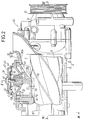
- the mechanical supercharger SC is comprised of a main rotor 7 and a gate rotor 8 which are a pair of screw rotors meshed with each other and rotatably supported in a housing 6. Air is drawn through an intake port 4 provided in one axial end of the housing 6 and is discharged through a discharge port 5 provided in the other axial end by the rotors 7 and 8 which are mechanically rotated by the engine body E.
- the housing 6 is comprised of a cylindrical member 9 formed into a bottomed cylindrical shape with one end closed by an end wall 9a, and an end wall member 10 coupled to the other end of the cylindrical member 9 to cover that open end.
- the cylindrical member 9 is formed to have a cross-sectional shape corresponding to the rotational locus described by the radially outer end of each of the rotors 7 and 8 and has an inner surface 9b which does not come into contact with the rotors 7 and 8.
- the intake port 4 is provided in the end wall 9a.
- the rotors 7 and 8 are secured to rotary shafts 11 and 12, respectively, which are carried at one end on the end wall 9a of the cylindrical member 9 by bearings 13 and 14, respectively, interposed therebetween.
- a cover 15 is coupled to the end wall member 10 to define a gear chamber 16 between the cover 15 itself and the end wall member 10.
- the other ends of the rotary shafts 11 and 12 pass through the end wall member 10 to project into the gear chamber 16.
- a sealing member 17 and a pair of bearings 18 are interposed between the rotary shaft 11 and the end wall member 10, and a sealing member 19 and a pair of bearings 20 are interposed between the rotary shaft 12 and the end wall member 10.
- Gears 22 and 23 which are meshed with each other are fixed to the rotary shafts 11 and 12, respectively, within the gear chamber 16 and in addition to the gear 22, a gear 24 is fixed to the rotary shaft 11.
- a shaft 25 is rotatably supported at one end on the end wall member 10 by a bearing 26 interposed therebetween and has an axis parallel to the rotary shafts 11 and 12.
- the shaft 25 extends through the cover 15 to project outwardly.
- a sealing member 27 and a pair of bearings 28 are interposed between the shaft 25 and the cover 15.
- a gear 29 which is meshed with the gear 24 is fixed to the shaft 25 within the gear chamber 16, and a pulley 30 is fixed to an outer end of the shaft 25 which projects from the cover 15. Power from a crankshaft 21 (see Fig. 1) of the engine E is transmitted to the pulley 30 through an endless belt which is not shown, thereby causing the main rotor 7 and the gate rotor 8 to be meshed with each other for rotation.
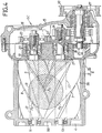
- a piston 31 is disposed on a side of the cylindrical portion 9 in the housing 6 at a location corresponding to meshed portions of the main rotor 7 and the gate rotor 8 for movement between a high-compression position (a position shown by dashed lines in Figs. 2 and 3) inwardly in a moving direction 32 substantially perpendicular to the axes of the screw rotors 7 and 8 and a low-compression position (a position shown by solid lines in Figs. 2 and 3) outwardly in the moving direction 32.
- the cylindrical member 9 is integrally provided at its side with a cylindrical guide portion 33 having a circular cross-section and extending in a direction perpendicular to the axes of the rotors 7 and 8, and the piston 31 is disposed within the cylindrical guide portion 33 for movement in the moving direction 32.
- the piston 31 is formed into a circular shape in cross section with the outside diameter thereof smaller than the inside diameter of the cylindrical guide portion 33 and is not supported by the cylindrical guide portion 33.
- the piston 31 is formed into a bottomed cylindrical shape with a closed end thereof directed into the housing 6 and provided at its opened end, i.e. at its outer end, with a collar 31a projecting radially outwardly.
- a large diameter portion 33a is provided through an outwardly facing step 33b on an inner surface of the cylindrical guide portion 33 at a location closer to the axially outer end thereof to receive the collar 31a and the extreme axial positions of the piston 31 are defined by a case 40 coupled to an outer end of the cylindrical guide portion 33 and by the step 33b.
- An axially extending key 34 is secured at one place in the inner surface of the cylindrical guide portion 33, and the collar 31a of the piston 31 is provided with a notch 31b into which the key 34 is fitted.
- the piston 31 is prevented by the key 34 from being rotated about its axis and is movable for a limited distance in the moving direction 32.
- the discharge port 5 is defined by cooperation of the piston 31 with a lead-out section 35 provided at an axial end of the housing 6 at a location corresponding to the meshed portions of the main rotor 7 and the gate rotor 8.
- the lead-out section 35 is comprised of a protrusion 9c provided at the open end of the cylindrical member 9 of the housing 6 to protrude outwardly from an inner surface 9b and a lead-out tube 36 provided on the end wall member 10.
- the portion of the piston 31 which faces into the housing 6 is formed in such a manner that the distance from the intake port 4 to a discharge starting position P E of the discharge port 5 at the time when the piston 31 is in the inward or high-compression position is larger than the distance from the intake port 4 to discharge starting positions P E ' and P E ' at the time when the piston 31 is in the outward or low-compression position.
- the piston 31 is provided, at the portion facing into the housing 6, with a surface 31c smoothly connected to the inner surface of the housing 6 and a surface 31d smoothly connected to an inner surface 35a of the lead-out section 35 when the piston 31 is in the high-compression position.
- a portion shown by the oblique dashed lines inclined downwardly to the right in Fig. 4 serves as the discharge port 5, and the junction between the surfaces 31c and 31d is the discharge starting position P E .
- a portion shown by the oblique dashed lines inclined both downwardly to the left and to the right in Fig. 4 serves as the discharge port 5 by the fact that the surface 31c is located more outwardly than the inner surface 9b of the housing 6, and the two positions in which grooves in the rotors 7 and 8 first communicate with the discharge port 5 in response to the rotation of the rotors 7 and 8 are the discharge starting positions P E ' and P E '.
- an internal compression ratio ⁇ is 1.0.
- the internal compression ratio ⁇ is, for example, 1.3.
- a drive means 38 is connected to the piston 31 and comprises the case 40 coupled to the outer end of the cylindrical guide portion 33 to define a back pressure chamber 39 between the case 40 itself and the piston 31, a diaphragm 41 housed in the case 40 and clamped at its peripheral edge by the case 40, and a spring 42 mounted in a compressed manner between the diaphragm 41 and the case 40.
- the case 40 is comprised of a pair of case members 43 and 44 coupled to each other, and the peripheral edge of the diaphragm 41 is clamped between the case members 43 and 44.
- the interior of the case 40 is divided by the diaphragm 41 into an atmospheric pressure chamber 45 inwardly in the moving direction 32 of the piston 31 and a control chamber 46 outwardly in the moving direction 32.
- the spring 42 is received in the atmospheric pressure chamber 45 to produce a spring force for biasing the diaphragm 41 in a direction to reduce the volume of the control chamber 46.
- a through hole 47 is provided at the central portion of the case member 44 that partitions the back pressure chamber 39 and the atmospheric pressure chamber 45 in the case 40, and a cylindrical bearing sleeve 48 is fitted and fixed in the through hole 47.
- the piston 31 is integrally provided with a connecting rod 31e extending in the moving direction 32.
- the bearing sleeve 48 slidably supports the connecting rod 31c and is connected to a central portion of the diaphragm 41.
- the piston 31 is not supported by the cylindrical guide portion 33 but rather is supported on the drive means 38 through the connecting rod 31e. This ensures that the sliding contact area of the piston 31 at the time when it is moved in the moving direction 32 can be reduced to minimize the friction loss and to prevent a sticking of the piston 31 within the cylindrical guide portion 33 due to a deformation of the piston 31 by thermal influence because the piston 31 is close to the discharge port 5 which has a relatively high temperature.
- Such drive means 38 allows the piston 31 to be moved inwardly to the high-compression position against the spring force of the spring 42 by increasing the pressure in the control chamber 46, and allows the piston 31 to be moved outwardly to the low-compression position by the spring force of the spring 42 when the pressure in the control chamber 46 is reduced.
- the piston 31 is also provided with a communication hole 49 for putting the back pressure chamber 39 into communication with the discharge port 5, so that the pressure in the back pressure chamber 39 is equal to the discharging pressure in the discharge port 5.
- a conduit 51 is connected to the intake passage 1 at a location corresponding to the point where the bypass passage 3 joins passage 1 downstream of the intercooler IC.
- a conduit 52 is connected to the control chamber 46 in the drive means 38.
- a switchover valve V is provided between a passage 54 opened into the atmosphere through an air cleaner 53 and the conduits 51 and 52 and is capable of alternatively switching-over the connection and disconnection of the passage 54 and the conduits 51 and 52.
- the switchover valve V is a solenoid valve which is capable of being shifted between a state in which the passage 54 is put into communication with the conduit 52 upon energization thereof, i.e., a state in which the atmospheric pressure is introduced into the control chamber 46, and a state in which the conduit 51 is put into communication with the conduit 52 upon de-energization thereof, i.e. a state in which a discharging pressure P 2 is introduced into the control chamber 46.
- the shifting operation of the switchover valve V and the operation of a bypass valve driving means 55 for driving a bypass valve V BP for opening and closing are controlled by a control means C including a microcomputer.
- the control means C controls the operations of the switchover valve V and the bypass valve driving means 55 in accordance with the throttle opening degree ⁇ TH of the throttle valve V TH , the engine revolution rate N E , the bypass opening degree ⁇ BP of the bypass valve V BP and the supercharge pressure P 2 .
- Signals are supplied to the control means C from a revolution rate detecting sensor S NE for detecting the engine revolution rate N E , a throttle opening degree detecting sensor S TH for detecting the throttle opening degree ⁇ TH and a supercharge pressure detecting sensor S P2 located in the middle of the conduit 51.
- a bypass control is possible. More specifically, when the temperature of the intake gas is too low or high, and/or the temperature of the engine-cooling water is too low or high, and/or the engine load is extremely high, the bypass valve V BP is fully opened at a fourth step S4 to stop the bypass control, and, thereafter, the processing is advanced to the twelfth step S12. When the engine is in a more normal operational state outside of the above conditions, the processing is advanced to a fifth step S5 to carry out the bypass control.
- the feed-back control region is established in an area in which the engine revolution rate N E is relatively low and the throttle opening degree ⁇ TH is relatively large.
- the supercharge pressure P 2 is difficult to vary by controlling the opening and closing of the throttle valve V TH , but controlling the opening and closing of the bypass valve V BP is primarily effective and therefore, the feed-back control is carried out.
- the supercharge pressure P 2 can be easily varied by controlling the opening and closing of the throttle valve V TH and, therefore, an open control is carried out. It should be noted that a boundary value between the feed-back control region and the open control region is set to have a hysteresis.
- the processing is advanced to a sixth step S6 at which a target opening degree ⁇ BPO of the bypass valve V BP at the open control is calculated from a map previously established as shown in Fig. 7 and thereafter, the processing is advanced to the twelfth step S12. More specifically, the target opening degree ⁇ BPO corresponding to the throttle opening degree ⁇ TH is previously set for every engine revolution rate N E and hence, the target opening degree ⁇ BPO , which becomes larger as the throttle opening degree ⁇ TH is lower, is calculated at the sixth step S6.
- the processing is advanced to a seventh step S7 at which a target supercharge pressure P 20 in the feed-back control region is calculated from a map previously established as shown in Fig. 8. More specifically, the target supercharge pressure P 20 corresponding to the throttle opening degree ⁇ TH is previously set for every engine revolution rate N E and hence, the target supercharge pressure P 20 corresponding to the engine revolution rate N E and the throttle opening degree ⁇ TH is calculated.
- a next eighth step S8 it is decided whether or not the difference between the target supercharge pressure P 20 calculated at the seventh step S7 and the supercharge pressure P 2 detected in the supercharge pressure detecting sensor S P2 is large. If it has been decided that such difference is large, the bypass valve V BP is fully closed and thereafter, the processing is advanced to the twelfth step S12.
- the processing is advanced to a tenth step S10 at which the target opening degree of the bypass valve V BP is calculated on the basis of the target supercharge pressure P 20 provided at the seventh step S7.
- a calculation of a deviation learning item used in a feed-back calculation is carried out.
- a limit check for judging whether or not the target opening degree of the bypass valve V BP is outside of a predetermined range is carried out.
- the bypass valve V BP is operated at a thirteenth step S13, and thereafter, at a fourteenth step S14, the control of the shifting operation of the switchover valve V is carried out according to a subroutine shown in Fig. 9.
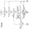
- a first step L1 of the subroutine in Fig 9 it is decided whether or not the throttle opening degree ⁇ TH exceeds a predetermined preset throttle opening degree ⁇ SOLL ( ⁇ TH > ⁇ SOLL ).
- the preset throttle opening degree ⁇ SOLL is used as a judging criterion for forcibly reducing the internal compression ratio on the basis of the fact that when the throttle opening degree ⁇ TH is small, it is not required to increase the internal compression ratio of the supercharger SC and the supercharge pressure P 2 also remains small, because the bypass valve V BP is open.
- the preset throttle opening degree ⁇ SOLL is set, for example, at 15/10 degrees to have a hysteresis.
- the processing is advanced to the second step L2 at which the counting down of a delay timer t that is set, for example, at 3 seconds is started.
- a third step L3 the switchover valve V is energized to permit the atmospheric pressure to be introduced into the control chamber 46.
- the processing is advanced to a fourth step L4 at which it is decided whether or not the engine revolution rate N E exceeds a preset revolution rate N SOL (N E > N SOL ).
- the present revolution rate N SOL is used as a judging criterion for forcibly reducing the internal compression ratio of the supercharger SC, because an increase in supercharge pressure P 2 cannot be expected in a condition in which the engine revolution rate N E is low.
- the preset revolution rate N SOL is set, for example, at 1,200/1,000 rpm to have a hysteresis. If it has been decided that N E ⁇ N SOL , the processing is advanced to the second step L2. On the other hand, if it has been decided that N E > N SOL , the processing is advanced to a fifth step L5.
- the throttle opening degree ⁇ TH exceeds a predetermined preset throttle opening degree ⁇ SOLH ( ⁇ TH > ⁇ SOLH ).
- the preset throttle opening degree ⁇ SOLH is used to judge whether or not the vehicle driver desires to accelerate.
- the preset throttle opening degree ⁇ SOLH is set, for example, at 60/50 degree to have a hysteresis. If it has been decided that ⁇ TH > ⁇ SOLH , the processing is advanced to a sixth step L6 on the basis of the decision that the vehicle driver desires to accelerate. At the sixth step L6, it is decided whether or not the supercharge pressure P 2 exceeds a preset supercharge pressure P SOLH (P 2 > P SOLH ).
- the preset supercharge pressure P SOLH is used to avoid noise that normally is produced due to pulsing when the internal compression ratio of the supercharger SC is in a condition in which a sufficient supercharge pressure P 2 cannot be obtained, even if the driver desires to accelerate.
- the preset supercharge pressure P SOLH is set, for example at 300 mm Hg. If it has been decided that P 2 ⁇ P SOLH , the processing is advanced to the second step L2. On the other hand, if it has been decided that P 2 > P SOLH , the processing is advanced to a thirteenth step L13.
- the processing is advanced to a seventh step L7 at which a searching of a switchover region on the basis of the engine revolution rate N E and the supercharge pressure P 2 is carried out.
- the processing is advanced to the seventh step L7 on conditions that the engine revolution rate N E and the throttle opening degree ⁇ TH are within a range shown by an oblique line inclined downwardly to the left in Fig. 10 on the basis of the decisions up to the fifth step L5, and at the seventh step L7 it is searched from a map established as shown in Fig. 11 whether either the atmospheric pressure or the supercharge pressure P 2 is to be introduced into the control chamber 46 in the drive means 38 within such range.
- a boundary value between an atmospheric pressure introducing region and a supercharge pressure introducing region has a hysteresis, and the supercharger SC in its high-compression state produces the larger supercharge pressure as the engine revolution rate N E is higher. Therefore, the boundary value is set such that the supercharge pressure introducing region is defined to introduce a larger supercharger pressure as the engine revolution rate N E is larger.
- step L8 If it has been decided at an eighth step L8 that the engine revolution rate N E and the supercharge pressure P 2 are in the atmospheric pressure introducing region, the processing is advanced to the second step L2. On the other hand, if it has been decided that the engine revolution rate N E and the supercharge pressure P 2 are in the supercharge introducing region, the processing is advanced to a ninth step L9.
- the processing is advanced to the thirteenth step L13 on the basis of the decision that there is a need to increase the speed of the vehicle. If it has been decided that the variation rate ⁇ ⁇ TH is smaller than the predetermined value, the processing is advanced to a tenth step L10. It is decided at the tenth step L10 whether the throttle opening degree ⁇ TH exceeds a preset throttle opening degree ⁇ DEL , e.g. 40 degree ( ⁇ TH > ⁇ DEL ).
- the processing is advanced to the thirteenth step L13, while if it has been decided that ⁇ TH ⁇ ⁇ DEL , the processing is advanced to an eleventh step Lll. Further, it is decided at the eleventh step Lll whether or not the engine revolution rate N E exceeds a preset revolution rate N DEL , e.g. 5,000 rpm (N E > N DEL ). If it has been decided that N E > N DEL , the processing is advanced to the thirteenth step L13, while if it has been decided that N E ⁇ N DEL , the processing is advanced to a twelfth step L12.
- the processing is advanced to the third step L3, while if it has been decided that the predetermined time has been lapsed and thus, "0" has been reached, the processing is advanced to the thirteenth step L13.
- the delay timer t is reset when the processing is advanced thereto from any of the sixth, ninth, tenth or eleventh steps L6, L9, L10 and Lll.
- the switchover valve V is operated to permit the supercharge pressure P 2 to be introduced into the control chamber 46.
- Such subroutine shown in Figs. 9A and 9B ensures that, as shown in Fig. 10, the operation of the switchover valve V is controlled in accordance with the engine revolution rate N E and the throttle opening degree ⁇ TH , so that the switchover valve V is shifted between the state in which the atmospheric pressure is introduced into the control chamber 46 to provide a compression ratio ⁇ of 1.0 and the state in which the supercharge pressure P 2 is introduced into the control chamber 46 to provide the compression ratio ⁇ of 1.3.
- the operation of the switchover valve V is controlled in a shifted manner according to the map shown in Fig.
- the piston 31 is movable in the moving direction substantially perpendicular to the axes of the main rotor 7 and the gate rotor 8 and hence, an increase in size of the housing 6 is avoided, ensuring that even if a distribution of temperature in an axial direction of the housing is produced, there is no disadvantage due to a difference in thermal expansion amount. In addition, a gas is not circulated and hence, a reduction in efficiency of operation is avoided.
- the provision of the communication hole 49 in the piston 31 for permitting the communication of the discharge port 5 with the back pressure chamber 39 ensures that an equal pressure can be applied to the opposite surfaces of the piston 31 to stably maintain the position of the piston 31, and the operation power required to move the piston 31 during shifting can be reduced.
- the piston 31 is brought into the high-compression position by a pressure discharged from the supercharger SC and, therefore, a dynamic pressure in the supercharger SC that would cause the position of the piston 31 to be unstable is avoided, thereby preventing a reduction in efficiency due to the position of the piston 31 being unstable.
- the piston 31 were brought into the high-compression position by the spring force of the spring 42, the position of the piston 31 would be unstable due to the dynamic pressure in the high-compression state.
- the shifting operation of the switchover valve V i.e., the switching-over of the internal compression rate ⁇ of the supercharger SC, is controlled in accordance with the supercharge pressure P 2 and the engine revolution rate N E and, therefore, pulsing due to a difference between the pressure in the supercharger SC and the supercharge pressure P 2 according to the engine revolution rate N E is avoided, thereby preventing a noise from being produced due to the pulsing.
- the bypass valve V BP In switchover from the low-compression state to the high-compression state, the bypass valve V BP is closed and hence, it is difficult for any noise produced on the discharge side of the supercharger SC to leak through the air cleaner A to the outside. Therefore, even if the switchover is delayed somewhat, the noise cannot leak out.
- the frequency of operation of the piston 31 can be suppressed to a small extent, leading to an improved durability, because the low-compression state cannot be switched over to the high-compression state unless the predetermined time, e.g., at least 3 seconds has elapsed.
- the driver has a strong desire to accelerate, i.e., if ⁇ ⁇ TH is equal to or more than the predetermined value, ⁇ TH > ⁇ DEL and N E > N DEL , the low-compression state is immediately switched over to the high-compression state and hence, there is no problem in the response time.
- bypass valve V BP is opened in switching-over from the high-compression state to the low-compression state, any noise can be prevented from being leaked to the outside by conducting the switching-over without a delay.
- a reference value of the supercharge pressure P 2 for switching-over from the low-compression state to the high-compression state is set such that it is larger as the engine revolution rate N E is larger, it is possible to switch over the internal compression ratio ⁇ to a value appropriately corresponding to the supercharge pressure P 2 , leading to an improvement in efficiency.
Landscapes
- Engineering & Computer Science (AREA)
- Chemical & Material Sciences (AREA)
- Combustion & Propulsion (AREA)
- Mechanical Engineering (AREA)
- General Engineering & Computer Science (AREA)
- Supercharger (AREA)
- Control Of Positive-Displacement Pumps (AREA)
Claims (5)
- Verfahren zum Steuern des Ladedrucks (P2) bei einem Verbrennungsmotor (E) mit einem mechanischen Lader (SC), welcher mit einer Kurbelwelle (21) des Verbrennungsmotors (E) verbunden ist, und mit einem Bypass (3), welcher Bypassventilmittel (VBP) zum Beeinflussen des Ladedrucks (P2) umfaßt, wobei ein Innenkompressionsverhältnis (ε) des mechanischen Laders (SC) zumindest in Abhängigkeit von dem Ladedruck (P2) und einer Motordrehzahl (NE) des Verbrennungsmotors (E) veränderbar ist, wobei das Innenkompressionsverhältnis (ε) des mechanischen Laders (SC) von einem Niederkompressionswert auf einen Hochkompressionswert umgeschaltet wird, wenn der Ladedruck (P2) einen Grenzwert überschritten hat, der mit zunehmender Motordrehzahl (NE) größer wird.
- Verfahren zum Steuern des Ladedrucks bei einem Verbrennungsmotor nach Anspruch 1,
dadurch gekennzeichnet,
daß beim Umschalten des Innenkompressionsverhältnisses (ε) des mechanischen Laders (SC) von dem Niederkompressionswert auf den Hochkompressionswert das Innenkompressionsverhältnis (ε) erhöht wird, nachdem ein Zustand, der eine Bedingung zum Umschalten des Innenkompressionsverhältnisses (ε) erfüllt, für eine vorbestimmte Zeit (t) aufrechterhalten ist. - Verfahren zum Steuern des Ladedrucks bei einem Verbrennungsmotor nach Anspruch 1 oder 2,
dadurch gekennzeichnet,
daß das Innenkompressionsverhältnis (ε) unmittelbar auf den Hochkompressionswert umgeschaltet wird, wenn ein Beschleunigungswunsch eines Fahrers erfaßt wird. - Verfahren zum Steuern des Ladedrucks bei einem Verbrennungsmotor nach Anspruch 1,
dadurch gekennzeichnet,
daß der Niederkompressionswert des Innenkompressionsverhältnisses (ε) 1,0 beträgt. - Verfahren zum Steuern eines Ladedrucks (P2) bei einem Verbrennungsmotor (E) nach einem der Ansprüche 1 bis 4,
dadurch gekennzeichnet,
daß das Innenkompressionverhältnis (ε) zumindest auf Grundlage des Ladedrucks (P2), der Drehzahl (NE) des Motors (E) und der Drosselöffnung (θ) verändert wird, wobeia) in einem ersten Bereich, in dem als erste Bedingungen die Drosselöffnung (θ) kleiner als ein erster gegebener Wert (θSOLL) ist und/oder die Drehzahl (NE) kleiner als ein erster gegebener Wert (NSOL) ist, das Innenkompressionsverhältnis (ε) auf den Niederkompressionswert eingestellt wird,b) in einem zweiten Bereich, in dem als zweite Bedingungen die Drosselöffnung (θ) größer als der erste gegebene Wert (θSOLL), aber kleiner als ein zweiter gegebener Wert (θDEL) ist und die Drehzahl (NE) größer als der erste gegebene Wert (NSOL), aber kleiner als ein zweiter gegebener Wert (NDEL) ist, das Innenkompressionsverhältnis (ε) bei dem Grenzwert von dem Niederkompressionswert auf den Hochkompressionswert am Ende einer vorbestimmten, bei Erfüllung der zweiten Bedingungen beginnenden Zeit (t) umgeschaltet wird, c) in einem dritten Bereich, in dem als dritte Bedingungen die Drosselöffnung (θ) größer als der zweite gegebene Wert (θDEL) ist und/oder die Drehzahl (NE) größer als der zweite gegebene Wert (NDEL) ist, während die ersten Bedingungen nicht erfüllt sind, die Innenkompressionsrate (ε) bei dem Grenzwert ohne Verzögerung auf den Hochkompressionswert umgeschaltet wird.
Applications Claiming Priority (2)
| Application Number | Priority Date | Filing Date | Title |
|---|---|---|---|
| JP300229/90 | 1990-11-06 | ||
| JP2300229A JP2524257B2 (ja) | 1990-11-06 | 1990-11-06 | 内燃機関における過給圧制御方法 |
Publications (3)
| Publication Number | Publication Date |
|---|---|
| EP0484884A2 EP0484884A2 (de) | 1992-05-13 |
| EP0484884A3 EP0484884A3 (en) | 1993-06-16 |
| EP0484884B1 true EP0484884B1 (de) | 1997-08-27 |
Family
ID=17882273
Family Applications (1)
| Application Number | Title | Priority Date | Filing Date |
|---|---|---|---|
| EP91118844A Expired - Lifetime EP0484884B1 (de) | 1990-11-06 | 1991-11-05 | Verfahren zum Steuern des Aufladedruckes einer Brennkraftmaschine |
Country Status (4)
| Country | Link |
|---|---|
| US (1) | US5207206A (de) |
| EP (1) | EP0484884B1 (de) |
| JP (1) | JP2524257B2 (de) |
| DE (1) | DE69127421T2 (de) |
Families Citing this family (7)
| Publication number | Priority date | Publication date | Assignee | Title |
|---|---|---|---|---|
| JPH05231159A (ja) * | 1991-12-26 | 1993-09-07 | Honda Motor Co Ltd | 内燃機関における過給圧制御装置 |
| DE102005014922B4 (de) * | 2005-04-01 | 2017-10-05 | Audi Ag | Mechanischer Lader für eine Verbrennungskraftmaschine |
| US7726285B1 (en) | 2005-04-01 | 2010-06-01 | Hansen Craig N | Diesel engine and supercharger |
| US8539769B2 (en) | 2009-10-14 | 2013-09-24 | Craig N. Hansen | Internal combustion engine and supercharger |
| US8813492B2 (en) * | 2009-10-14 | 2014-08-26 | Hansen Engine Corporation | Internal combustion engine and supercharger |
| US9273619B2 (en) * | 2012-12-10 | 2016-03-01 | Fca Us Llc | Supercharged engine and method of control |
| DE102013213352B4 (de) * | 2013-03-28 | 2015-04-02 | Mtu Friedrichshafen Gmbh | Verfahren zum Betrieb einer Brennkraftmaschine, Regelung für eine Brennkraftmaschine und Brennkraftmaschine |
Family Cites Families (13)
| Publication number | Priority date | Publication date | Assignee | Title |
|---|---|---|---|---|
| DE3144712C2 (de) * | 1981-11-11 | 1984-11-29 | Pierburg Gmbh & Co Kg, 4040 Neuss | Verfahren zur Regelung der Füllung von Brennkraftmaschinen mit Verbrennungsgas sowie Vorrichtung zum Durchführen dieses Verfahrens |
| JPS63239313A (ja) * | 1987-03-25 | 1988-10-05 | Fuji Heavy Ind Ltd | 可変容量型過給機装置 |
| US4887580A (en) * | 1987-03-30 | 1989-12-19 | Pneumofore S.P.A. | Supercharger device for reciprocating internal combustion engines, particularly for motor vehicles |
| US4862144A (en) * | 1987-04-21 | 1989-08-29 | Tao Billy S K | Movement monitor |
| US4826412A (en) * | 1987-05-01 | 1989-05-02 | Kabushiki Kaisha Kobe Seiko Sho | Mechanically driven screw supercharger |
| JPS63285219A (ja) * | 1987-05-14 | 1988-11-22 | Kobe Steel Ltd | スクリュ形機械式過給機 |
| DE3803044A1 (de) * | 1988-02-02 | 1989-08-10 | Gutehoffnungshuette Man | Schiebergeregelte schraubenrotormaschine und damit ausgeruesteter aufgeladener verbrennungsmotor |
| JP2766294B2 (ja) * | 1988-03-31 | 1998-06-18 | マツダ株式会社 | エンジンの過給装置 |
| JPH02221634A (ja) * | 1989-02-23 | 1990-09-04 | Mazda Motor Corp | 過給機付エンジンの制御手段 |
| JPH0318625A (ja) * | 1989-06-14 | 1991-01-28 | Mazda Motor Corp | 機械式過給機付エンジンの制御装置 |
| JP2727662B2 (ja) * | 1989-06-20 | 1998-03-11 | 石川島播磨重工業株式会社 | 機械駆動式過給機 |
| JPH0772495B2 (ja) * | 1989-07-28 | 1995-08-02 | マツダ株式会社 | エンジンの過給装置 |
| JPH0388916A (ja) * | 1989-08-31 | 1991-04-15 | Mazda Motor Corp | 圧縮式過給機の制御装置 |
-
1990
- 1990-11-06 JP JP2300229A patent/JP2524257B2/ja not_active Expired - Fee Related
-
1991
- 1991-11-05 DE DE69127421T patent/DE69127421T2/de not_active Expired - Fee Related
- 1991-11-05 EP EP91118844A patent/EP0484884B1/de not_active Expired - Lifetime
- 1991-11-06 US US07/788,553 patent/US5207206A/en not_active Expired - Fee Related
Also Published As
| Publication number | Publication date |
|---|---|
| US5207206A (en) | 1993-05-04 |
| DE69127421D1 (de) | 1997-10-02 |
| EP0484884A3 (en) | 1993-06-16 |
| DE69127421T2 (de) | 1998-01-02 |
| JPH04175422A (ja) | 1992-06-23 |
| JP2524257B2 (ja) | 1996-08-14 |
| EP0484884A2 (de) | 1992-05-13 |
Similar Documents
| Publication | Publication Date | Title |
|---|---|---|
| US4563997A (en) | Control system and method for comprex supercharger | |
| EP0484885B1 (de) | Schraubenpumpe | |
| US5427079A (en) | Supercharged engine with variable ratio drive supercharger | |
| JP3924510B2 (ja) | 排気タービン過給機の可変ノズル開度制御装置 | |
| EP0484884B1 (de) | Verfahren zum Steuern des Aufladedruckes einer Brennkraftmaschine | |
| US4995347A (en) | Intake device of a two stroke engine with supercharger bypass passage | |
| US4763477A (en) | Method of controlling supercharge pressure and apparatus for realizing the same | |
| CA3063158A1 (en) | Wastegate sizing for turbocharger for a two-stroke engine | |
| US5347972A (en) | Supercharge pressure control system in internal combustion engine | |
| EP0392330B1 (de) | Steuerungssystem für einen Motor mit mechanischem Lader | |
| US12006860B2 (en) | Turbocharger system for a two-stroke engine | |
| KR930005961B1 (ko) | 미끄럼 밸브로 제어되는 스크류 회전자 기계를 구비한 과급식 내연기관 | |
| US5730586A (en) | Supercharger with integral by-pass passage | |
| US4756284A (en) | Intake system for internal combustion engine | |
| EP0151407A1 (de) | Laderantrieb für aufgeladenen Verbrennungsmotor | |
| JP2770364B2 (ja) | 内燃機関の機械式過給装置 | |
| JP2572213Y2 (ja) | スクリュー型ポンプ | |
| JP3247225B2 (ja) | エンジンの過給装置 | |
| EP0877158A2 (de) | Steuerung für Dieselmotor. | |
| JP3137801B2 (ja) | エンジンの過給装置 | |
| JPH0734889A (ja) | 過給機付エンジンの制御方法 | |
| JPH1061452A (ja) | 機械式過給機付エンジンの過給制御装置 | |
| JP2829533B2 (ja) | エンジンの機械式過給機制御装置 | |
| JPS63239313A (ja) | 可変容量型過給機装置 | |
| JPH0734887A (ja) | 過給機付エンジンの制御方法 |
Legal Events
| Date | Code | Title | Description |
|---|---|---|---|
| PUAI | Public reference made under article 153(3) epc to a published international application that has entered the european phase |
Free format text: ORIGINAL CODE: 0009012 |
|
| AK | Designated contracting states |
Kind code of ref document: A2 Designated state(s): DE GB |
|
| PUAL | Search report despatched |
Free format text: ORIGINAL CODE: 0009013 |
|
| AK | Designated contracting states |
Kind code of ref document: A3 Designated state(s): DE GB |
|
| 17P | Request for examination filed |
Effective date: 19930827 |
|
| 17Q | First examination report despatched |
Effective date: 19940826 |
|
| GRAG | Despatch of communication of intention to grant |
Free format text: ORIGINAL CODE: EPIDOS AGRA |
|
| GRAH | Despatch of communication of intention to grant a patent |
Free format text: ORIGINAL CODE: EPIDOS IGRA |
|
| GRAH | Despatch of communication of intention to grant a patent |
Free format text: ORIGINAL CODE: EPIDOS IGRA |
|
| GRAA | (expected) grant |
Free format text: ORIGINAL CODE: 0009210 |
|
| AK | Designated contracting states |
Kind code of ref document: B1 Designated state(s): DE GB |
|
| REF | Corresponds to: |
Ref document number: 69127421 Country of ref document: DE Date of ref document: 19971002 |
|
| PLBE | No opposition filed within time limit |
Free format text: ORIGINAL CODE: 0009261 |
|
| STAA | Information on the status of an ep patent application or granted ep patent |
Free format text: STATUS: NO OPPOSITION FILED WITHIN TIME LIMIT |
|
| 26N | No opposition filed | ||
| PGFP | Annual fee paid to national office [announced via postgrant information from national office to epo] |
Ref country code: GB Payment date: 19981106 Year of fee payment: 8 |
|
| PG25 | Lapsed in a contracting state [announced via postgrant information from national office to epo] |
Ref country code: GB Free format text: LAPSE BECAUSE OF NON-PAYMENT OF DUE FEES Effective date: 19991105 |
|
| GBPC | Gb: european patent ceased through non-payment of renewal fee |
Effective date: 19991105 |
|
| PGFP | Annual fee paid to national office [announced via postgrant information from national office to epo] |
Ref country code: DE Payment date: 20031113 Year of fee payment: 13 |
|
| PG25 | Lapsed in a contracting state [announced via postgrant information from national office to epo] |
Ref country code: DE Free format text: LAPSE BECAUSE OF NON-PAYMENT OF DUE FEES Effective date: 20050601 |