EP0485003A1 - Vorrichtung zum Verändern der Stromversorgung eines ohmschen Verbrauchers, wie z.B. einer Glühlampe - Google Patents
Vorrichtung zum Verändern der Stromversorgung eines ohmschen Verbrauchers, wie z.B. einer Glühlampe Download PDFInfo
- Publication number
- EP0485003A1 EP0485003A1 EP91202747A EP91202747A EP0485003A1 EP 0485003 A1 EP0485003 A1 EP 0485003A1 EP 91202747 A EP91202747 A EP 91202747A EP 91202747 A EP91202747 A EP 91202747A EP 0485003 A1 EP0485003 A1 EP 0485003A1
- Authority
- EP
- European Patent Office
- Prior art keywords
- power
- tmd
- ton
- value
- toff
- Prior art date
- Legal status (The legal status is an assumption and is not a legal conclusion. Google has not performed a legal analysis and makes no representation as to the accuracy of the status listed.)
- Withdrawn
Links
- 125000004122 cyclic group Chemical group 0.000 claims abstract description 4
- 238000001514 detection method Methods 0.000 claims description 6
- 230000003068 static effect Effects 0.000 claims description 6
- 230000001360 synchronised effect Effects 0.000 claims description 4
- 238000013475 authorization Methods 0.000 claims description 3
- 230000000295 complement effect Effects 0.000 claims description 3
- 230000005764 inhibitory process Effects 0.000 claims description 3
- 230000001934 delay Effects 0.000 claims description 2
- 230000010354 integration Effects 0.000 claims description 2
- 238000007493 shaping process Methods 0.000 claims description 2
- 230000003252 repetitive effect Effects 0.000 description 7
- 230000001795 light effect Effects 0.000 description 6
- 230000000630 rising effect Effects 0.000 description 6
- 240000000966 Allium tricoccum Species 0.000 description 4
- 239000003990 capacitor Substances 0.000 description 3
- 238000010586 diagram Methods 0.000 description 3
- 210000000056 organ Anatomy 0.000 description 2
- 230000003321 amplification Effects 0.000 description 1
- 238000000429 assembly Methods 0.000 description 1
- 230000001419 dependent effect Effects 0.000 description 1
- 230000000977 initiatory effect Effects 0.000 description 1
- 238000009434 installation Methods 0.000 description 1
- 238000003199 nucleic acid amplification method Methods 0.000 description 1
- 230000003534 oscillatory effect Effects 0.000 description 1
- 230000000737 periodic effect Effects 0.000 description 1
- 230000001960 triggered effect Effects 0.000 description 1
Images


Classifications
-
- H—ELECTRICITY
- H05—ELECTRIC TECHNIQUES NOT OTHERWISE PROVIDED FOR
- H05B—ELECTRIC HEATING; ELECTRIC LIGHT SOURCES NOT OTHERWISE PROVIDED FOR; CIRCUIT ARRANGEMENTS FOR ELECTRIC LIGHT SOURCES, IN GENERAL
- H05B39/00—Circuit arrangements or apparatus for operating incandescent light sources
- H05B39/04—Controlling
- H05B39/08—Controlling by shifting phase of trigger voltage applied to gas-filled controlling tubes also in controlled semiconductor devices
- H05B39/083—Controlling by shifting phase of trigger voltage applied to gas-filled controlling tubes also in controlled semiconductor devices by the variation-rate of light intensity
Definitions
- the invention relates to a device intended to vary the supply of a resistive load, such as an incandescent lamp, and is particularly intended for obtaining variable light effects which find their application in fields such as advertising, shows. ...
- the present invention aims to overcome this drawback and aims to provide a device for varying the supply of a resistive load providing a very wide range of intensity settings allowing in particular to obtain a wide variety of light effects.
- Another object of the invention is to provide a device which can have several operating modes providing different intensity variations.
- this device comprises a control member adapted to control its operation in static mode allowing manual adjustment of the supply voltage of the load.
- this device further comprises a control member adapted to control its operation in flashing mode corresponding to a negligible rise and fall time TMD.
- This third operating mode therefore corresponds to repetitive operation, apart from the rise and fall times which are negligible compared to the operating frequency of the device.
- the zero and maximum value steps always have durations that can be adjusted separately.
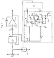
- this device consists of three sub-assemblies: a power supply 2, a triac 3 with its control 4, and a cycle generator 5.
- the power supply module 2 of a type known per se, is adapted to generate voltages +/- 15 Volts DC intended for supplying the various mounting circuits.
- this module provides a signal synchronized with the sector necessary for control 4 of the triac 3.
- the control 4 of the latter also of a type known per se, receives pulses synchronized with the sector. After processing and a function of the voltage level requested by the cycle generator 5, these control pulses generated by the logic make it possible to adjust the triac start time and therefore the supply voltage of the load 1.
- the generator of cycles 5 is intended to supply the continuous reference value V.Ref to the control of the triac 3. It is made up of a generator of ramps 6 with adjustable slopes, a level detection 7 and two time delays 8, 9.
- the ramp generator 6 manages the rise and fall times TMD of the reference voltage V.Ref as well as the maximum value VMAX.
- the level 7 detection triggers the timers 8 or 9 and ensures the cyclic operation.
- the timers 8, 9 allow respectively the setting of the TOFF and TON durations of the stages.
- the cycle generator 5 also manages the device as a function of the cycles requested by the user (static, repetitive, flashing).
- the ramp generator 6 provides the analog output signal, and performs an integration function. It is triggered on rising and falling by authorization signals T1 and T2 delivered respectively by timers 8 and 9 and the slope is automatically inhibited when the output voltage of this generator 6 reaches either the zero value or the VMAX value manually adjusted using an adjustment potentiometer 10.
- This generator 6 comprises connected in series, a hysteresis comparator 11, a manual adjustment potentiometer 12 making it possible to adjust the duration TMD of the slopes as a function of the voltage coming from this potentiometer, and an adjustable integrator 13 comprising a capacity 14.
- the comparator 11 is adapted to deliver an inhibition signal TF either of negative voltage as long as the voltage VMAX is not reached, during the phase of rise of the output voltage of the generator 6, or of positive voltage as long as the zero voltage is not reached, when the output voltage is lowering, or oscillatory voltage when a plateau is reached.
- the timers 8, 9 are made up of flip-flops of type "D" conventionally comprising a clock input C, two outputs Q, Q ⁇ and a Reset R input, and carry out a monostable function making it possible to respectively adjust the durations TON and TOFF of the stages of maximum value and zero value.
- the clock input C of one of these timers 8, conventionally active when it receives a rising edge, receives the inhibition signal TF delivered by the ramp generator 6.
- the clock input C of the other timer 9, for its part, receives a signal complementary to the signal TF, the inversion of this signal being carried out by the detection of peliers consisting of a NAND gate 7.
- each of these timers 8, 9 is connected to the Reset input R of the other timer 9, 8 by means of a diode, respectively 15, 16.
- the timer 8 receives a rising edge corresponding to the VMAX value step, it switches to this rising edge.
- This switching passes through the output Q which, by means of the diode 15, inhibits the other time delay 9.
- the time delay 9 receives a rising edge of the signal complementary to the signal TF corresponding to the zero value level, it switches on this rising edge and inhibits the time delay 8 via the diode 16.
- each timer 8 or 9 causes the charging of a capacity respectively 17, 18, the charging speed and therefore the duration of the maximum and zero value steps is manually determined by means of potentiometers 19, 20.
- potentiometers 19, 20 In each of the circuits comprising a potentiometer 19, 20 and a capacitor 17, 18, there is, in addition, a diode, respectively 21, 22, performing an "OR" function.
- the duration of a plateau of maximum or zero value, adjusted respectively by the potentiometers 19, 20 therefore corresponds to the time taken by the capacitors 17, 18 to reach the input level of the timers 8, 9.
- the Reset R input of these timers 8, 9 is activated, which causes the output Q to reset and the output to switch Q ⁇ which changes to the value 1.
- the timer 8 or 9 concerned then triggers a pulse signal, respectively T1 for timer 8 and T2 for timer 9, which controls the switching of an RS 23 flip-flop which itself switches a controllable switch 24 of the MOSFET type which triggers the ramp generator 6, either on ascent or on descent.
- the device finally comprises, on the one hand, a switch 25 making it possible to select either a static operation or a repetitive operation, and a second switch 26 making it possible to select, in repetitive operating mode, a flashing operation corresponding to the minimum value of the potentiometer 12 for adjusting the TMD duration of the ramps.
- Such a device therefore makes it possible to select on the one hand three different operating modes, static, repetitive and flashing, and in particular in the repeating operating mode to obtain very varied light effects thanks to the possibility of modifying the duration TMD of the ramps , the times TOFF and TON of the stages, and the maximum value VMAX.
Landscapes
- Circuit Arrangement For Electric Light Sources In General (AREA)
Applications Claiming Priority (2)
| Application Number | Priority Date | Filing Date | Title |
|---|---|---|---|
| FR9013646 | 1990-10-31 | ||
| FR9013646A FR2668675B1 (fr) | 1990-10-31 | 1990-10-31 | Dispositif destine a faire varier l'alimentation d'une charge resistive, telle que lampe a incandescence. |
Publications (1)
| Publication Number | Publication Date |
|---|---|
| EP0485003A1 true EP0485003A1 (de) | 1992-05-13 |
Family
ID=9401828
Family Applications (1)
| Application Number | Title | Priority Date | Filing Date |
|---|---|---|---|
| EP91202747A Withdrawn EP0485003A1 (de) | 1990-10-31 | 1991-10-23 | Vorrichtung zum Verändern der Stromversorgung eines ohmschen Verbrauchers, wie z.B. einer Glühlampe |
Country Status (2)
| Country | Link |
|---|---|
| EP (1) | EP0485003A1 (de) |
| FR (1) | FR2668675B1 (de) |
Cited By (2)
| Publication number | Priority date | Publication date | Assignee | Title |
|---|---|---|---|---|
| ES2056725A2 (es) * | 1992-06-09 | 1994-10-01 | Verdu Enrique Aguilar | Temporizador electronico mejorado con seleccion de tiempos por medio de interruptores miniatura. |
| ES2056724A2 (es) * | 1992-06-09 | 1994-10-01 | Verdu Enrique Aguilar | Sistema electronico con funciones de encendido, apagado, y regulacion de alumbrado incandescente, mediante pulsadores. |
Citations (5)
| Publication number | Priority date | Publication date | Assignee | Title |
|---|---|---|---|---|
| US3868546A (en) * | 1973-03-26 | 1975-02-25 | Hunt Electronics Company | Light dimming system for controlling brightness and rate of change of brightness of lights |
| US3898383A (en) * | 1973-07-24 | 1975-08-05 | Charles G Herbits | Automatic dimming and recycleable lamp |
| EP0037315A1 (de) * | 1980-03-28 | 1981-10-07 | ELAM LIMITED Société dite | Steuerungsanordnung der Helligkeitsänderungen einer Lichtanlage im Laufe der Zeit |
| US4389598A (en) * | 1981-02-10 | 1983-06-21 | Smith Robert M | Disco light assembly |
| DE3901877A1 (de) * | 1988-01-22 | 1989-10-19 | Janusz Dziubinski | Methode der elektrischen beleuchtung fuer langwierige, kontinuierliche und anstrengende augenarbeit und schaltung zur steuerung der lichtstaerke der elektrischen beleuchtung fuer langwierige, kontinuierliche und anstrengende augenarbeit |
-
1990
- 1990-10-31 FR FR9013646A patent/FR2668675B1/fr not_active Expired - Fee Related
-
1991
- 1991-10-23 EP EP91202747A patent/EP0485003A1/de not_active Withdrawn
Patent Citations (5)
| Publication number | Priority date | Publication date | Assignee | Title |
|---|---|---|---|---|
| US3868546A (en) * | 1973-03-26 | 1975-02-25 | Hunt Electronics Company | Light dimming system for controlling brightness and rate of change of brightness of lights |
| US3898383A (en) * | 1973-07-24 | 1975-08-05 | Charles G Herbits | Automatic dimming and recycleable lamp |
| EP0037315A1 (de) * | 1980-03-28 | 1981-10-07 | ELAM LIMITED Société dite | Steuerungsanordnung der Helligkeitsänderungen einer Lichtanlage im Laufe der Zeit |
| US4389598A (en) * | 1981-02-10 | 1983-06-21 | Smith Robert M | Disco light assembly |
| DE3901877A1 (de) * | 1988-01-22 | 1989-10-19 | Janusz Dziubinski | Methode der elektrischen beleuchtung fuer langwierige, kontinuierliche und anstrengende augenarbeit und schaltung zur steuerung der lichtstaerke der elektrischen beleuchtung fuer langwierige, kontinuierliche und anstrengende augenarbeit |
Cited By (2)
| Publication number | Priority date | Publication date | Assignee | Title |
|---|---|---|---|---|
| ES2056725A2 (es) * | 1992-06-09 | 1994-10-01 | Verdu Enrique Aguilar | Temporizador electronico mejorado con seleccion de tiempos por medio de interruptores miniatura. |
| ES2056724A2 (es) * | 1992-06-09 | 1994-10-01 | Verdu Enrique Aguilar | Sistema electronico con funciones de encendido, apagado, y regulacion de alumbrado incandescente, mediante pulsadores. |
Also Published As
| Publication number | Publication date |
|---|---|
| FR2668675A1 (fr) | 1992-04-30 |
| FR2668675B1 (fr) | 1993-01-15 |
Similar Documents
| Publication | Publication Date | Title |
|---|---|---|
| EP0058609B1 (de) | Regelverfahren der Speisung eines Gleichstrommotors und Vorrichtung zu dessen Ausführung | |
| EP0037315B1 (de) | Steuerungsanordnung der Helligkeitsänderungen einer Lichtanlage im Laufe der Zeit | |
| EP0788678B1 (de) | Verfahren und schaltungsanordnung zur leistungssteuerung einer last durch ein phasensteuerungssystem | |
| EP0485003A1 (de) | Vorrichtung zum Verändern der Stromversorgung eines ohmschen Verbrauchers, wie z.B. einer Glühlampe | |
| FR2498938A1 (fr) | Circuit de commande pour un bras de billard electronique | |
| CH626759A5 (en) | Device for controlling the speed of a DC motor | |
| FR2490040A1 (fr) | Dephaseur pour decaler a distance les phases de signaux d'entree et de sortie ayant une meme frequence choisie | |
| EP0488881B1 (de) | Regelvorrichtung für die von einem Wechselstromgenerator abgegebene Batteriespannung | |
| FR2468527A1 (fr) | Dispositif de regulation de puissance destine a transmettre l'energie d'une source de courant alternatif a un distributeur vibrant, et ensemble comprenant un tel dispositif et un tel distributeur | |
| FR2631506A1 (fr) | Circuit de securite pour cuisiniere electrique | |
| EP0196960A1 (de) | Steuereinrichtung für schnell zu betätigende elektromagnetische Anordnungen | |
| EP0465381B1 (de) | Regelvorrichtung für die Rotationsgeschwindigkeit eines elektrischen Motors | |
| FR2509488A1 (fr) | Circuit electronique de regulation et de commande pour une source de pression et de vide | |
| EP0424280B1 (de) | Elektronische Ansteuerungsschaltung für einen gleichstromgespeisten Schwingmotor | |
| EP0952680A1 (de) | Übertragung eines Betriebsartsignals über eine Wechselspannungsversorgungsleitung | |
| FR2537804A1 (fr) | Circuit de commande de la base d'un transistor de puissance utilise en commutation a haute tension | |
| FR2494522A1 (fr) | Dispositif de commande d'un moteur a courant continu | |
| EP0068970B1 (de) | Stabilisierte Zweipunkt-Steuervorrichtung mit konstanter Periode, und elektrische Speisevorrichtung versehen mit solch einer Steuervorrichtung | |
| EP0021867A1 (de) | Gegen Schwankungen der Eingangsspannung und der Ausgangsleistung geregelte Zerhacker-Spannungsversorgungsschaltung, insbesondere für Fernsehempfänger | |
| FR1465565A (fr) | Variateur de tension perfectionné | |
| FR2468940A1 (fr) | Regulateur de tension pour alternateur destine a la charge d'une batterie | |
| FR2493067A1 (fr) | Perfectionnements aux dispositifs d'alimentation pour moteurs a vitesse variable | |
| EP0201372A1 (de) | Anordnung zur Erzeugung eines Signals komplexer Form durch lineare Approximation | |
| FR2606229A1 (fr) | Systeme de commande d'un moteur asynchrone monophase destine a l'entrainement d'un objet tel qu'un store du type a lames orientables | |
| FR2471082A1 (fr) | Generateur commutable delivrant de |
Legal Events
| Date | Code | Title | Description |
|---|---|---|---|
| PUAI | Public reference made under article 153(3) epc to a published international application that has entered the european phase |
Free format text: ORIGINAL CODE: 0009012 |
|
| AK | Designated contracting states |
Kind code of ref document: A1 Designated state(s): AT BE CH DE DK ES FR GB GR IT LI LU NL SE |
|
| 17P | Request for examination filed |
Effective date: 19921016 |
|
| 17Q | First examination report despatched |
Effective date: 19940613 |
|
| STAA | Information on the status of an ep patent application or granted ep patent |
Free format text: STATUS: THE APPLICATION IS DEEMED TO BE WITHDRAWN |
|
| 18D | Application deemed to be withdrawn |
Effective date: 19941102 |