EP0485088B1 - Gasbrenner - Google Patents
Gasbrenner Download PDFInfo
- Publication number
- EP0485088B1 EP0485088B1 EP91309785A EP91309785A EP0485088B1 EP 0485088 B1 EP0485088 B1 EP 0485088B1 EP 91309785 A EP91309785 A EP 91309785A EP 91309785 A EP91309785 A EP 91309785A EP 0485088 B1 EP0485088 B1 EP 0485088B1
- Authority
- EP
- European Patent Office
- Prior art keywords
- burner
- flame
- electrodes
- gas burner
- gas
- Prior art date
- Legal status (The legal status is an assumption and is not a legal conclusion. Google has not performed a legal analysis and makes no representation as to the accuracy of the status listed.)
- Expired - Lifetime
Links
- 239000007789 gas Substances 0.000 claims description 64
- 239000011810 insulating material Substances 0.000 claims description 13
- 230000002093 peripheral effect Effects 0.000 claims description 10
- 239000000203 mixture Substances 0.000 claims description 7
- 239000012777 electrically insulating material Substances 0.000 claims description 6
- 239000004020 conductor Substances 0.000 claims description 5
- 230000000694 effects Effects 0.000 claims description 4
- 239000002737 fuel gas Substances 0.000 claims description 4
- 230000001419 dependent effect Effects 0.000 claims 4
- 239000002184 metal Substances 0.000 description 7
- 238000001514 detection method Methods 0.000 description 6
- 238000005273 aeration Methods 0.000 description 2
- 230000002159 abnormal effect Effects 0.000 description 1
- 230000008033 biological extinction Effects 0.000 description 1
- 229910010293 ceramic material Inorganic materials 0.000 description 1
- 238000002485 combustion reaction Methods 0.000 description 1
- 238000009833 condensation Methods 0.000 description 1
- 230000005494 condensation Effects 0.000 description 1
- 229910052878 cordierite Inorganic materials 0.000 description 1
- 238000010586 diagram Methods 0.000 description 1
- JSKIRARMQDRGJZ-UHFFFAOYSA-N dimagnesium dioxido-bis[(1-oxido-3-oxo-2,4,6,8,9-pentaoxa-1,3-disila-5,7-dialuminabicyclo[3.3.1]nonan-7-yl)oxy]silane Chemical compound [Mg++].[Mg++].[O-][Si]([O-])(O[Al]1O[Al]2O[Si](=O)O[Si]([O-])(O1)O2)O[Al]1O[Al]2O[Si](=O)O[Si]([O-])(O1)O2 JSKIRARMQDRGJZ-UHFFFAOYSA-N 0.000 description 1
- 230000009977 dual effect Effects 0.000 description 1
- 239000000428 dust Substances 0.000 description 1
- 238000010892 electric spark Methods 0.000 description 1
- 239000004519 grease Substances 0.000 description 1
- 230000014759 maintenance of location Effects 0.000 description 1
- 238000004088 simulation Methods 0.000 description 1
- 239000004071 soot Substances 0.000 description 1
Images

Classifications
-
- F—MECHANICAL ENGINEERING; LIGHTING; HEATING; WEAPONS; BLASTING
- F23—COMBUSTION APPARATUS; COMBUSTION PROCESSES
- F23Q—IGNITION; EXTINGUISHING-DEVICES
- F23Q3/00—Igniters using electrically-produced sparks
- F23Q3/006—Details
-
- F—MECHANICAL ENGINEERING; LIGHTING; HEATING; WEAPONS; BLASTING
- F23—COMBUSTION APPARATUS; COMBUSTION PROCESSES
- F23D—BURNERS
- F23D14/00—Burners for combustion of a gas, e.g. of a gas stored under pressure as a liquid
- F23D14/02—Premix gas burners, i.e. in which gaseous fuel is mixed with combustion air upstream of the combustion zone
- F23D14/04—Premix gas burners, i.e. in which gaseous fuel is mixed with combustion air upstream of the combustion zone induction type, e.g. Bunsen burner
- F23D14/06—Premix gas burners, i.e. in which gaseous fuel is mixed with combustion air upstream of the combustion zone induction type, e.g. Bunsen burner with radial outlets at the burner head
-
- F—MECHANICAL ENGINEERING; LIGHTING; HEATING; WEAPONS; BLASTING
- F23—COMBUSTION APPARATUS; COMBUSTION PROCESSES
- F23N—REGULATING OR CONTROLLING COMBUSTION
- F23N5/00—Systems for controlling combustion
- F23N5/24—Preventing development of abnormal or undesired conditions, i.e. safety arrangements
- F23N5/242—Preventing development of abnormal or undesired conditions, i.e. safety arrangements using electronic means
-
- F—MECHANICAL ENGINEERING; LIGHTING; HEATING; WEAPONS; BLASTING
- F24—HEATING; RANGES; VENTILATING
- F24C—DOMESTIC STOVES OR RANGES ; DETAILS OF DOMESTIC STOVES OR RANGES, OF GENERAL APPLICATION
- F24C3/00—Stoves or ranges for gaseous fuels
- F24C3/10—Arrangement or mounting of ignition devices
- F24C3/103—Arrangement or mounting of ignition devices of electric ignition devices
Definitions
- the present invention relates to gas burners and, more particularly, to gas burners having automatic reignition systems which, when the burner flame is extinguished while air/gas mixture is being supplied to the burner, are energised in order to reignite the air/gas mixture.
- the invention is especially, thought not exclusively, applicable to toroidal aerated gas burners of the kind in which a mixture of gas and air is supplied to a burner head and issues from main burner ports formed in the outer wall thereof where, commonly, secondary air is entrained or available for providing a gas/air ratio suitable for automatic ignition and combustion when a control for the burner is turned on, and in which such burners include a detachable cover plate disposed over the central air spaced bounded by the toroidal burner body and supported in spaced relationship with respect to the burner head so as to provide an annular gap therebetween through which secondary air from the central air space can be entrained at the main burner ports, and to provide protection for the ignition source of an electric spark ignition system.
- This kind of burner will hereinafter be referred to as a toroidal aerated gas burner as hereinbefore described.
- US-A-2152790 discloses an automatic safety pilot burner associated with a main burner.
- the pilot burner comprises a plurality of equally spaced metal electrodes which define a spark gap with a generally central terminal part of the burner.
- a spark generating means is energised manually by the pressing of a push button in an associated electrical circuit to produce a spark at the spark gap to ignite fuel gas supplied to the pilot burner. If the flame of the pilot burner is accidentally extinguished the gas supply to the pilot burner and also to the main burner is shut off automatically.
- DE-A-1962708 discloses a fuel gas burner arrangement providing for ignition across a spark gap of the burner and, in the case of an abnormal extinguishing of the flame, the generation of a number of re-ignition impulses followed, if re-ignition is unsuccessful, by shut off of the gas to the burner and actuation of a warning device.
- the spark gap is defined between the actual burner body and a single electrode mounted in the immediate vicinity of the burner body. This single electrode fulfils a dual purpose: on the one hand, serving as part of the ignition system to produce sparks to ignite the gas at the burner; and on the other hand, serving to determine changes in the flame ionization in the spark gap due to the presence or absence of a flame.
- An object of the present invention is to provide a gas burner arrangement in which the occurrence of nuisance sparking is reduced.
- the invention consists in a gas burner arrangement comprising a gas burner wherein spark-gaps are defined between a plurality of flame electrodes and opposing electrode means, a spark generator and a flame failure sensing means which is electrically connected to the flame electrodes in order to sense the absence of flame only when there is an absence of flame extending from each flame electrode to the opposing electrode means at the same time and, in response to such absence of flame, the flame failure means initiates energisation of the spark generator to effect sparking and reignition of the burner.
- the flame failure sensing means may employ either flame rectification or flame conduction, each of which is well known to those skilled in the art of flame failure sensing means.
- flame rectification is preferred. This is because in connection with single sparking electrode burners it has been found that condensation or a build up of deposits of dust, grease or soot on a burner may occur and, if so, bridge the sparking gap to cause electrical tracking which in the case where flame conduction is utilised simulates the presence of a flame and flame conduction with the result that reignition sparking can be suppressed when required on the extinction of a flame; whereas in the case where flame rectification is utilised, such electrical tracking does not produce such problems and thus the required reignition sparking can be more reliable should the flame be extinguished.
- the gas burner arrangement may incorporate or be associated with other equipment such as safety devices and/or control devices or systems which are energised or operated either in response to the cessation of energisation of the spark generator when successful ignition or reignition of the burner has occurred, or in response to failure of ignition or reignition of the burner to occur within a predetermined sparking time period from the start of the energisation of the spark generator.
- safety devices and/or control devices or systems which are energised or operated either in response to the cessation of energisation of the spark generator when successful ignition or reignition of the burner has occurred, or in response to failure of ignition or reignition of the burner to occur within a predetermined sparking time period from the start of the energisation of the spark generator.
- an extractor fan or cooker hood may be energised and in addition, or alternatively, if the burner fails to ignite or re-ignite after the predetermined period a valve, such as a solenoid valve, may be operated so as to close
- the gas burner may comprise an annular burner head which has main burner ports around the periphery thereof and opening outwardly of the burner head.
- the gas burner may be a toroidal aerated gas burner of the kind hereinbefore described having a detachable cover plate which comprises an electrically insulating material from which the plurality of electrodes depend, an electrical contact region about which the electrodes are disposed, and electrically conducting means substantially concealed by the insulating material and connecting the electrodes with the electrical contact region, and wherein the burner head provides the opposing electrode means.
- the dimensioning and arrangement of the electrodes and burner ports are such that, when the burner is in use, the electrodes are bathed in the flames from the main ports, even when the burner is turned down to simmer rate, whereby there is a reliable sufficient flame current which facilitates good flame rectification response.
- connection means comprises a plurality of lengths of electrically conducting material equal in number to the number of electrodes with each conducting length connected to a respective one of the electrodes.
- Each conducting length may extend through a respective passageway in the insulating material.
- the passageway may extend from, or from closely adjacent to, the peripheral edge of the cover plate.
- the electrical contact region may comprise an electrical conducting projection or spigot which depends from the insulating material.
- the electrically conducting projection or spigot is fitted into a socket mounted within the central air space of the toroidal burner, with the socket having electrical conducting means which is contacted by the projection thereby providing an electrical connection connecting the plurality of electrodes to the spark ignition/reignition system and flame failure sensing means.
- the electrical conducting means may comprise a metallised layer on the internal surface of the socket.
- the electrodes lie on an imaginary circle, are substantially equally spaced from each other, and are substantially equi-distant from the electrical contact region.
- the invention also consists in a cover plate for use in a gas burner arrangement wherein the gas burner is of the kind hereinbefore described, the cover plate comprising an electrically insulating material, a plurality of electrodes which depend from the insulating material and which are disposed about an electrical contact region, and electrically conducting means substantially concealed by the insulating material and connecting the electrodes with the electrical contact region.
- the invention consists in a cooker hob plate having mounted thereon at least one gas burner arrangement according to this invention, and also in a gas cooker incorporating such a hob plate or otherwise comprising one or more gas burner arrangements according to this invention.
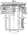
- the annular ring 3 supports the burner head 5 which is located by an annular boss 9 on the toroidal body 2.
- the annular ring 3 is located in position on the shoulder of the body 2 so as to define an annular gap 10 which communicates with an annular space 11 of the toroidal body through slots 12 formed in the lower edge of the ring 3 for the emission of an air/gas mixture for producing a small flame ring designed to retain and stabilise the main burner flame at the ports 6.
- the air/gas mixture can be supplied to the burner through an inlet 13 which communicates with the annular space 11.
- the spillage cap 7 (shown also in Figure 1) is comprised of an electrically insulating material, for example a ceramic material, such as cordierite and three flame electrodes 15 depend from the underside and adjacent the periphery of, the cap.
- the electrodes 15 are disposed about a central recess 16 in the underside of the cap so as to lie on an imaginary circle, be substantially equally spaced from each other and be substantially equi-distant from the central recess.
- a cylindrical metal projection or spigot 17 is located in the recess 16 to form an electrical contact region, the function of which will be described below.
- each length 18 is integral with respective electrode 15 and extends through a respective bore or channel 19 formed in the insulating material 14.
- the bores 19 form passageways which extend radially from the recess 16 to the peripheral edge 19 of the cap 7.
- the three passageways 19 lie substantially in a common plane.
- the projection 17 has three openings or recesses 17a at 120° intervals around its circumference which, when the projection is located in the recess 16, are aligned with the radially inner ends 19a of the bores 19 which open into the recess. This enables the lengths 18 of electrically conducting material to be inserted at the periphery of the cap into the bores 19 and push fitted into the recesses 17a in the projection 17.
- the burner arrangement as shown in the present embodiment has three spark gaps 20. Each spark gap is defined between a respective one of the flame electrodes 15 and an opposing portion 5a of the metal burner head 5 which serves as the opposing electrode means.
- each electrode 15 a respective orifice 23 extends through the outer wall of the burner from the inner peripheral surface 24 in the direction upwardly and outwardly to the outer peripheral surface 22 of the outer wall towards the electrode.
- air/gas mixture to be combusted is directed from the toroidal body 2 towards the electrodes 15 by the respective orifices 23 to produce ignition flames which ignite the air/gas misture issuing from the main burner ports 6.
- the underside of the cap comprises recesses 25 for fitting over the upstanding projections 8 on the top of the burner head to ensure that the cap and burner head are mounted in a correct relative orientation so that the ignition flame orifices 23 are aligned with the electrodes 15.
- the depths of the recesses 25 are less than the heights of the upstanding projections 8 and thus the underside 7b of the spillage cap 7 is in spaced relationship above the upper surface 5b of the burner head 5.
- the metal projection 17 is fitted into a socket 26 which is made of an electrically insulating material and mounted within the central air space of the toroidal burner by means of a bracket 27 projecting inwardly from the inner wall of the toroidal burner.
- the internal surface of the socket comprises a metallised layer 28 which provides electrical connection between the projection 17 and a terminal 29 which extends through the base 30 of the socket 26 and is also in contact with the metallised layer.
- High tension voltage is supplied to the electrodes 15 via the terminal 29 which is connected to a spark generator 31 to effect sparking across the spark gaps 20 to ignite the burner when the supply of gas is turned on and a flame failure sensing means 32 using the flame rectification principle to sense the presence/absence of flame across the spark gaps.
- spark generator 31 and flame failure sensing means 32 are commonly manufactured as a single unit.
- the flame failure sensing means 32 senses the absence of flame only when there is an absence of flame extending from each flame electrode 15 to the burner head 5 at the same time. In response to such absence of flame the flame failure sensing means 32 initiates energisation of the spark generator 31 to effect sparking again and reignition of the burner. In the present embodiment, Applicants have found that ignition and reignition may occur across any of the three spark gaps.
- the flame electrodes 15 are bathed in the flames from the main burner ports 6 and this results in desired relatively high flame currents being sensed by the flame rectification detection system.
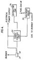
- FIG. 4 there is shown in schematic form an electric circuit in which the spark generator/flame failure sensing unit 31,32 is connected to a timer/control unit 33 which is connected to and sends electrical signals to an extractor fan 34 associated with a gas cooker (not shown) in which the burner arrangement is incorporated and a solenoid valve 35 located in a fuel gas supply pipe leading to the burner.
- Unit 31,32 and timer/control unit 33 are also connected to an electrical power supply.
- the circuit is so designed that when the energisation of the spark generator ceases on the completion of successful ignition or re-ignition of the burner, the extractor fan is activated, and if the burner fails to ignite or re-ignite within a predetermined time period from the start of the energisation of the spark generator, the solenoid valve is operated to close off the supply of gas through the pipe to the burner.
- the operations of the extractor fan and solenoid valve are under the control of the timer/control unit 33 which in turn receives signals at the appropriate times from the spark generator/flame failure sensing unit.
- the flame electrodes may be located outwardly of the periphery of an annular burner head with generally radially outwardly facing main burner ports.
- the burner head may again serve to provide the opposing electrode means.
- each flame electrode may be operably associated with its own specific opposing electrode which is separate from the burner head.
Landscapes
- Engineering & Computer Science (AREA)
- Chemical & Material Sciences (AREA)
- Combustion & Propulsion (AREA)
- Mechanical Engineering (AREA)
- General Engineering & Computer Science (AREA)
- Gas Burners (AREA)
- Control Of Combustion (AREA)
Claims (26)
- Gasbrenneranordnung, mit einem Gasbrenner, bei dem Funkenstrecken (20) zwischen einer Vielzahl von Flammenelektroden (15) und einer gegenüberliegenden Elektrodeneinrichtung (5) definiert sind, einem Funkengenerator (31) und einer Flammenausfallerfassungseinrichtung (32), die elektrisch mit den Flammenelektroden verbunden ist, um das Fehlen der Flamme nur dann zu erfassen, wenn ein Fehlen der Flamme gleichzeitig zwischen jeder Flammenelektrode (15) und der gegenüberliegenden Elektrodeneinrichtung (5) vorliegt, wobei als Antwort auf ein solches Fehlen der Flamme die Flammenausfallerfassungseinrichtung (32) das Aktivieren des Funkengenerators (31) auslöst, um die Funkenbildung und die Wiederzündung des Brenners zu bewirken.
- Gasbrenneranordnung nach Anspruch 1, bei der der Gasbrenner einen ringförmigen Brennerkopf (5) aufweist, der Hauptbrennerdurchgangsöffnungen (6) um die Peripherie desselben herum besitzt, die sich zur Außenseite des Brennerkopfes hin öffnen.
- Gasbrenneranordnung nach Anspruch 2, bei der der Gasbrenner ein ringförmiger, belüfteter Gasbrenner der oben beschriebenen Art mit einer ablösbaren Abdeckplatte (7) ist, welche ein elektrisch isolierendes Material, aus dem die Vielzahl der Elektroden (15) nach unten vorspringt, einen elektrischen Kontaktbereich (17), um den die Elektroden angeordnet sind, und elektrisch leitende Mittel (18) aufweist, die von dem isolierenden Material im wesentlichen umschlossen sind und die Elektroden (15) mit dem elektrischen Kontaktbereich (17) verbinden, und wobei der Brennerkopf (5) die gegenüberliegende Elektrodeneinrichtung bereitstellt.
- Gasbrenneranordnung nach Anspruch 3, bei der die Verbindungsmittel (18) eine Vielzahl von Längen aus elektrisch leitendem Material aufweisen, die zahlenmäßig der Anzahl der Elektroden (15) entsprechen, wobei jede leitende Länge an eine entsprechende Elektrode der genannten Elektroden angeschlossen ist.
- Gasbrenneranordnung nach Anspruch 4, bei der sich jede leitende Länge (18) durch einen entsprechenden Durchgang (19) im isolierenden Material erstreckt.
- Gasbrenneranordnung nach irgendeinem Anspruch 3 bis 5, bei der der elektrische Kontaktbereich (17) einen elektrisch leitenden Vorsprung aufweist, der aus dem isolierenden Material nach unten vorspringt.
- Gasbrenneranordnung nach Anspruch 6, bei der der elektrisch leitende Vorsprung (17) in eine Buchse (26) eingepaßt ist, welche im zentralen Luftraum des ringförmigen Brenners montiert ist, wobei die Buchse eine elektrisch leitende Einrichtung (28) besitzt, die von dem Vorsprung berührt wird, wodurch ein elektrischer Anschluß geschaffen wird, der die Vielzahl der Elektroden (15) mit dem Funkenzündung-/Wiederzündungssystem (31) und der Flammenausfallerfassungseinrichtung (32) verbindet.
- Gasbrenneranordnung nach Anspruch 6 oder 7, rückbezogen auf Anspruch 4 oder 5, bei der der leitende Vorsprung (17) und die leitenden Längen (18) aneinander befestigt sind.
- Gasbrenneranordnung nach irgendeinem vorhergehenden Anspruch, bei dem die Elektroden (15) auf einem gedachten Kreis liegen und im wesentlichen gleichmäßig untereinander beabstandet sind.
- Gasbrenneranordnung nach irgendeinem der Ansprüche 3 bis 8, oder nach Anspruch 9, rückbezogen auf irgendeinen der Ansprüche 3 bis 8, bei der die Elektroden (15) zum elektrischen Kontaktbereich (17) hin im wesentlichen gleichen Abstand haben.
- Gasbrenneranordnung nach Anspruch 3 oder nach irgendeinem der Ansprüche 4 bis 10, direkt oder indirekt rückbezogen auf Anspruch 3, bei der sich für jede Elektrode (15) eine entsprechende Öffnung (23) durch die äußere Wand des Brennerkopfes (5) von der inneren peripheren Oberfläche in eine allgemein zur zugehörigen Elektrode hin weisende Richtung erstreckt, so daß bei in Betrieb befindlicher Brenneranordnung die zu verbrennende Luft/Gas-Mischung vom ringförmigen Körper her durch die entsprechende Öffnung zur zugehörigen Elektrode gerichtet wird.
- Gasbrenneranordnung nach Anspruch 11, bei der die Spitze jeder Elektrode (15) an einer Stelle endet, die außerhalb der äußeren peripheren Oberfläche (22) der äußeren Wand (21) des Brennerkopfes (5) liegt, und bei der sich jede Öffnung (23) nach oben hin in ihre jeweilige Richtung weg vom Brennerkopf erstreckt.
- Gasbrenneranordnung nach Anspruch 12, bei der sich jede Öffnung (23) von der inneren peripheren Oberfläche (24) zur äußeren peripheren Oberfläche (22) der äußeren Wand (21) des Brennerkopfes (5) erstreckt.
- Gasbrenneranordnung nach irgendeinem vorhergehenden Anspruch, bei dem die Flammenausfallerfassungseinrichtung (32) das Flammenausrichtungsprinzip benutzt, um das Fehlen oder das Vorhandensein der Flamme zu erfassen oder abzutasten.
- Gasbrenneranordnung nach irgendeinem vorhergehenden Anspruch in Kombination mit einem Ventil (35), das in einer Brenngasversorgungsleitung zur Lieferung von Gas an den Brenner angeordnet ist, wobei das Ventil zum Absperren der Versorgungsleitung und somit der Gaszufuhr zum Brenner bedienbar ist, und zwar als Antwort auf das Versagen des Brenners, nach einer vorbestimmten Periode versuchten Zündens zu zünden oder wiederzuzünden.
- Gasbrenneranordnung nach irgendeinem vorhergehenden Anspruch in Kombination mit einem Sauglüfter (34) oder einer Kochhaube, welche veranlaßt werden, als Antwort auf das Zünden oder Wiederzünden des Brenners in Betrieb zu gehen.
- Abdeckplatte zur Verwendung bei der Gasbrenneranordnung nach Anspruch 3, die ein elektrisch isolierendes Material, eine Vielzahl von Elektroden (15), welche aus dem isolierenden Material vorspringen und um einen elektrischen Kontaktbereich (17) angeordnet sind, und elektrisch leitende Einrichtungen (18) aufweist, die im wesentlichen vom isolierenden Material umschlossen sind und die Elektroden mit dem elektrischen Kontaktbereich verbinden.
- Abdeckplatte nach Anspruch 17, bei der die Verbindungseinrichtungen (18) eine Vielzahl von Längen elektrisch leitenden Materials umfassen, die zahlenmäßig der Anzahl der Elektroden (15) entsprechen, wobei jede leitende Länge mit einer entsprechenden Elektrode der genannten Elektroden verbunden ist.
- Abdeckplatte nach Anspruch 17 oder 18, bei der der elektrische Kontaktbereich (17) einen elektrisch leitenden Vorsprung aufweist, der nach unten aus dem isolierenden Material vorspringt.
- Abdeckplatte nach Anspruch 19, rückbezogen auf Anspruch 18, bei der der leitende Vorsprung (17) und die leitenden Längen (18) aneinander befestigt sind.
- Abdeckplatte nach irgendeinem der Ansprüche 17 bis 20, bei der die Elektroden (15) auf einem gedachten Kreis liegen und untereinander gleichmäßig beabstandet sind.
- Abdeckplatte nach irgendeinem der Ansprüche 17 bis 21, bei der die Elektroden (15) vom elektrischen Kontaktbereich (17) im wesentlichen gleichen Abstand haben.
- Abdeckplatte nach irgendeinem der Ansprüche 17 bis 22, die dazu bestimmt ist, als Überlaufkappe zu dienen.
- Kochertragplatte, auf der mindestens eine einzelne Gasbrenneranordnung nach irgendeinem der Ansprüche 1 bis 16 montiert ist.
- Gasbrenneranordnung, die eine oder mehrere Gasbrenneranordnungen gemäß irgendeinem der Ansprüche 1 bis 16 in sich aufnimmt.
- Gaskocher, der eine Tragplatte nach Anspruch 24 in sich aufnimmt.
Applications Claiming Priority (2)
| Application Number | Priority Date | Filing Date | Title |
|---|---|---|---|
| GB9023452 | 1990-10-29 | ||
| GB9023452A GB2249381B (en) | 1990-10-29 | 1990-10-29 | Gas burners |
Publications (2)
| Publication Number | Publication Date |
|---|---|
| EP0485088A1 EP0485088A1 (de) | 1992-05-13 |
| EP0485088B1 true EP0485088B1 (de) | 1994-11-23 |
Family
ID=10684488
Family Applications (1)
| Application Number | Title | Priority Date | Filing Date |
|---|---|---|---|
| EP91309785A Expired - Lifetime EP0485088B1 (de) | 1990-10-29 | 1991-10-23 | Gasbrenner |
Country Status (4)
| Country | Link |
|---|---|
| EP (1) | EP0485088B1 (de) |
| DE (1) | DE69105257T2 (de) |
| ES (1) | ES2064922T3 (de) |
| GB (2) | GB2249381B (de) |
Families Citing this family (6)
| Publication number | Priority date | Publication date | Assignee | Title |
|---|---|---|---|---|
| US5119802A (en) * | 1991-09-09 | 1992-06-09 | Cherry David N | Gas cooktop appliance for use with downdraft ventilation system |
| IT1260828B (it) * | 1992-07-13 | 1996-04-22 | Defendi Srl Off Mec | Bruciatore a gas con termocoppia di controllo |
| ES2188332B1 (es) * | 2000-09-22 | 2004-11-16 | Bsh Fabricacion, S.A. | Sistema de fijacion del cuerpo encendedor en encimeras de gas. |
| US7850447B1 (en) * | 2004-07-30 | 2010-12-14 | Wolf Appliance, Inc. | Dual disc electrode |
| IL199631A0 (en) * | 2008-07-07 | 2010-04-29 | Diehl Bgt Defence Gmbh & Co Kg | Microwave generator |
| EP3640540B1 (de) | 2018-10-16 | 2021-04-21 | Orkli, S. Coop. | Kochgerät |
Family Cites Families (11)
| Publication number | Priority date | Publication date | Assignee | Title |
|---|---|---|---|---|
| US2152790A (en) * | 1936-09-17 | 1939-04-04 | Partlow Corp | Automatic safety pilot burner |
| DE1529135A1 (de) * | 1966-09-02 | 1970-01-29 | Edgar Frank | Gasherdzuendbrenner |
| FR1598786A (de) * | 1968-12-27 | 1970-07-06 | ||
| GB1344610A (en) * | 1969-11-29 | 1974-01-23 | Cannon Ind Ltd | Boiling burners for hotplates of domestic gas cookers |
| GB1473959A (en) * | 1975-08-14 | 1977-05-18 | Aeromatic Co Ltd | Natural gas burners |
| GB1543618A (en) * | 1977-02-18 | 1979-04-04 | British Gas Corp | Gas burners |
| GB1579829A (en) * | 1977-07-29 | 1980-11-26 | Bray & Co Ltd Geo | Gas burners |
| GB2082752B (en) * | 1980-08-21 | 1984-03-14 | British Gas Corp | Burner igniter/detector |
| FR2598486B1 (fr) * | 1986-05-12 | 1988-08-12 | Sourdillon Airindex Sa | Bruleur a gaz de type plat, notamment pour appareil menager, agence pour etre premuni contre les effets de fluctuation de la pression de l'air primaire |
| AU589320B2 (en) * | 1987-06-18 | 1989-10-05 | Matsushita Electric Industrial Co., Ltd. | Heating apparatus |
| FR2620199B1 (fr) * | 1987-09-08 | 1992-02-28 | Sourdillon Airindex Sa | Perfectionnements apportes aux bruleurs a gaz a flamme pilote et chapeau de bruleur pour ces bruleurs perfectionnes |
-
1990
- 1990-10-29 GB GB9023452A patent/GB2249381B/en not_active Expired - Fee Related
-
1991
- 1991-10-23 EP EP91309785A patent/EP0485088B1/de not_active Expired - Lifetime
- 1991-10-23 ES ES91309785T patent/ES2064922T3/es not_active Expired - Lifetime
- 1991-10-23 DE DE69105257T patent/DE69105257T2/de not_active Expired - Fee Related
-
1994
- 1994-05-24 GB GB9410352A patent/GB2276233B/en not_active Expired - Fee Related
Also Published As
| Publication number | Publication date |
|---|---|
| GB2276233A (en) | 1994-09-21 |
| GB9410352D0 (en) | 1994-07-13 |
| GB2276233B (en) | 1995-01-18 |
| DE69105257D1 (de) | 1995-01-05 |
| GB2249381A (en) | 1992-05-06 |
| EP0485088A1 (de) | 1992-05-13 |
| GB2249381B (en) | 1995-01-11 |
| GB9023452D0 (en) | 1990-12-12 |
| DE69105257T2 (de) | 1995-03-30 |
| ES2064922T3 (es) | 1995-02-01 |
Similar Documents
| Publication | Publication Date | Title |
|---|---|---|
| US5468145A (en) | Sealed gas burner assembly | |
| US6322352B1 (en) | Gas burner system | |
| US5119802A (en) | Gas cooktop appliance for use with downdraft ventilation system | |
| US5924860A (en) | Thickwall gas burner assembly | |
| EP0331815B1 (de) | Gasbrenner mit Funkenzündung | |
| US20030064335A1 (en) | Flame burner ignition system | |
| US5492469A (en) | Gaseous fuel burner and dual probe spark electrode therefor | |
| US20020034713A1 (en) | Ignition flame for gas cooking burners | |
| US5961311A (en) | Burner re-ignition system having a plurality of flame sensors | |
| CN112178699B (zh) | 燃气灶的燃烧器、燃气灶及燃气灶的点火装置 | |
| US5246365A (en) | Reignition device for a gas burner | |
| US5765542A (en) | Cooktop gas burner | |
| EP0485088B1 (de) | Gasbrenner | |
| GB2153988A (en) | Gas burner | |
| US4561840A (en) | Safety device for oil burner | |
| US5498154A (en) | Burner with over surface ignitor and high limit control | |
| US5934896A (en) | Method and apparatus for generating dual point top burner spark for gas range and dual port burner incorporating same | |
| JP4299456B2 (ja) | こんろ用バーナ | |
| US5275555A (en) | Holding and covering a gas pilot | |
| JPS61285317A (ja) | ガスバ−ナ | |
| US3844704A (en) | Burner and ignition system | |
| CN223782843U (zh) | 燃烧器及灶具 | |
| KR200328477Y1 (ko) | 깔때기형점화기가설치된파일럿버너 | |
| KR0133638Y1 (ko) | 오방전 방지용 버너 | |
| JP3464303B2 (ja) | ガスバーナ |
Legal Events
| Date | Code | Title | Description |
|---|---|---|---|
| PUAI | Public reference made under article 153(3) epc to a published international application that has entered the european phase |
Free format text: ORIGINAL CODE: 0009012 |
|
| AK | Designated contracting states |
Kind code of ref document: A1 Designated state(s): BE DE ES FR GB IT NL |
|
| 17P | Request for examination filed |
Effective date: 19920518 |
|
| 17Q | First examination report despatched |
Effective date: 19920921 |
|
| GRAA | (expected) grant |
Free format text: ORIGINAL CODE: 0009210 |
|
| AK | Designated contracting states |
Kind code of ref document: B1 Designated state(s): BE DE ES FR GB IT NL |
|
| ITF | It: translation for a ep patent filed | ||
| REF | Corresponds to: |
Ref document number: 69105257 Country of ref document: DE Date of ref document: 19950105 |
|
| REG | Reference to a national code |
Ref country code: ES Ref legal event code: FG2A Ref document number: 2064922 Country of ref document: ES Kind code of ref document: T3 |
|
| ET | Fr: translation filed | ||
| PLBE | No opposition filed within time limit |
Free format text: ORIGINAL CODE: 0009261 |
|
| STAA | Information on the status of an ep patent application or granted ep patent |
Free format text: STATUS: NO OPPOSITION FILED WITHIN TIME LIMIT |
|
| 26N | No opposition filed | ||
| REG | Reference to a national code |
Ref country code: GB Ref legal event code: 732E |
|
| PGFP | Annual fee paid to national office [announced via postgrant information from national office to epo] |
Ref country code: FR Payment date: 19980911 Year of fee payment: 8 |
|
| PGFP | Annual fee paid to national office [announced via postgrant information from national office to epo] |
Ref country code: NL Payment date: 19980923 Year of fee payment: 8 |
|
| PGFP | Annual fee paid to national office [announced via postgrant information from national office to epo] |
Ref country code: DE Payment date: 19980925 Year of fee payment: 8 |
|
| PGFP | Annual fee paid to national office [announced via postgrant information from national office to epo] |
Ref country code: ES Payment date: 19981009 Year of fee payment: 8 |
|
| PGFP | Annual fee paid to national office [announced via postgrant information from national office to epo] |
Ref country code: BE Payment date: 19981016 Year of fee payment: 8 |
|
| PGFP | Annual fee paid to national office [announced via postgrant information from national office to epo] |
Ref country code: GB Payment date: 19981117 Year of fee payment: 8 |
|
| PG25 | Lapsed in a contracting state [announced via postgrant information from national office to epo] |
Ref country code: GB Free format text: LAPSE BECAUSE OF NON-PAYMENT OF DUE FEES Effective date: 19991023 |
|
| PG25 | Lapsed in a contracting state [announced via postgrant information from national office to epo] |
Ref country code: ES Free format text: LAPSE BECAUSE OF NON-PAYMENT OF DUE FEES Effective date: 19991024 |
|
| PG25 | Lapsed in a contracting state [announced via postgrant information from national office to epo] |
Ref country code: BE Free format text: LAPSE BECAUSE OF NON-PAYMENT OF DUE FEES Effective date: 19991031 |
|
| BERE | Be: lapsed |
Owner name: BG PUBLIC LIMITED COMPANY Effective date: 19991031 |
|
| PG25 | Lapsed in a contracting state [announced via postgrant information from national office to epo] |
Ref country code: NL Free format text: LAPSE BECAUSE OF NON-PAYMENT OF DUE FEES Effective date: 20000501 |
|
| GBPC | Gb: european patent ceased through non-payment of renewal fee |
Effective date: 19991023 |
|
| PG25 | Lapsed in a contracting state [announced via postgrant information from national office to epo] |
Ref country code: FR Free format text: LAPSE BECAUSE OF NON-PAYMENT OF DUE FEES Effective date: 20000630 |
|
| NLV4 | Nl: lapsed or anulled due to non-payment of the annual fee |
Effective date: 20000501 |
|
| PG25 | Lapsed in a contracting state [announced via postgrant information from national office to epo] |
Ref country code: DE Free format text: LAPSE BECAUSE OF NON-PAYMENT OF DUE FEES Effective date: 20000801 |
|
| REG | Reference to a national code |
Ref country code: FR Ref legal event code: ST |
|
| REG | Reference to a national code |
Ref country code: ES Ref legal event code: FD2A Effective date: 20001113 |
|
| PG25 | Lapsed in a contracting state [announced via postgrant information from national office to epo] |
Ref country code: IT Free format text: LAPSE BECAUSE OF NON-PAYMENT OF DUE FEES;WARNING: LAPSES OF ITALIAN PATENTS WITH EFFECTIVE DATE BEFORE 2007 MAY HAVE OCCURRED AT ANY TIME BEFORE 2007. THE CORRECT EFFECTIVE DATE MAY BE DIFFERENT FROM THE ONE RECORDED. Effective date: 20051023 |