EP0485098A1 - Appareil de transport et de l'alignement de feuilles - Google Patents
Appareil de transport et de l'alignement de feuilles Download PDFInfo
- Publication number
- EP0485098A1 EP0485098A1 EP91309955A EP91309955A EP0485098A1 EP 0485098 A1 EP0485098 A1 EP 0485098A1 EP 91309955 A EP91309955 A EP 91309955A EP 91309955 A EP91309955 A EP 91309955A EP 0485098 A1 EP0485098 A1 EP 0485098A1
- Authority
- EP
- European Patent Office
- Prior art keywords
- sheet
- alignment device
- sheet transport
- sheets
- roll
- Prior art date
- Legal status (The legal status is an assumption and is not a legal conclusion. Google has not performed a legal analysis and makes no representation as to the accuracy of the status listed.)
- Withdrawn
Links
- 239000002184 metal Substances 0.000 claims abstract description 14
- 230000037431 insertion Effects 0.000 claims 1
- 238000003780 insertion Methods 0.000 claims 1
- 229910000831 Steel Inorganic materials 0.000 description 5
- 239000010959 steel Substances 0.000 description 5
- 239000002245 particle Substances 0.000 description 2
- 239000004809 Teflon Substances 0.000 description 1
- 229920006362 Teflon® Polymers 0.000 description 1
- 238000007792 addition Methods 0.000 description 1
- 230000010365 information processing Effects 0.000 description 1
- 238000012986 modification Methods 0.000 description 1
- 230000004048 modification Effects 0.000 description 1
- 238000006467 substitution reaction Methods 0.000 description 1
- 238000011144 upstream manufacturing Methods 0.000 description 1
Images


Classifications
-
- B—PERFORMING OPERATIONS; TRANSPORTING
- B65—CONVEYING; PACKING; STORING; HANDLING THIN OR FILAMENTARY MATERIAL
- B65H—HANDLING THIN OR FILAMENTARY MATERIAL, e.g. SHEETS, WEBS, CABLES
- B65H3/00—Separating articles from piles
- B65H3/44—Simultaneously, alternately, or selectively separating articles from two or more piles
-
- B—PERFORMING OPERATIONS; TRANSPORTING
- B65—CONVEYING; PACKING; STORING; HANDLING THIN OR FILAMENTARY MATERIAL
- B65H—HANDLING THIN OR FILAMENTARY MATERIAL, e.g. SHEETS, WEBS, CABLES
- B65H5/00—Feeding articles separated from piles; Feeding articles to machines
- B65H5/06—Feeding articles separated from piles; Feeding articles to machines by rollers or balls, e.g. between rollers
- B65H5/062—Feeding articles separated from piles; Feeding articles to machines by rollers or balls, e.g. between rollers between rollers or balls
-
- B—PERFORMING OPERATIONS; TRANSPORTING
- B65—CONVEYING; PACKING; STORING; HANDLING THIN OR FILAMENTARY MATERIAL
- B65H—HANDLING THIN OR FILAMENTARY MATERIAL, e.g. SHEETS, WEBS, CABLES
- B65H5/00—Feeding articles separated from piles; Feeding articles to machines
- B65H5/36—Article guides or smoothers, e.g. movable in operation
- B65H5/38—Article guides or smoothers, e.g. movable in operation immovable in operation
Definitions
- the present invention relates to a sheet transport and alignment device particularly suitable for an image-reproducing machine, such as a laser printer, an electro-photocopier or other similar office machinery.
- the present invention relates to a device for conveying sheets of paper coming selectively from more than one direction to the register rolls or sheet alignment rolls, in such a way that each sheet is correctly positioned against the register or alignment rolls in the direction of advance.
- American Patent No. 4403851 discloses a copier in which the sheets of paper are taken selectively from different paper stacks, such as a first and a second cassette of conventional type, each containing around 250 sheets each, a large cassette positioned under the copier and containing about 1000 sheets, and a channel for the manual introduction of one sheet at a time, also known as a "by-pass".
- the sheets of paper are conveyed along three channels all leading to a zone immediately upstream of a pair of register rolls.
- a preferred embodiment provides a device for transporting sheets of paper arriving from different stacks or directions to a registration device for alignment of the sheet.
- a feed device takes sheets from a cassette and forwards them to a common registration device along a feed path.
- the adjacent roll is formed of rubber.
- the sheet transport device is introduced, for example, into a laser printer 10. It should be understood that this device may be fitted either to an electro-photocopier or to any office information processing machine in which the information is to be printed on sheets arriving from different stacks.
- the information to be printed is mostly in the form of images and/or text prepared by writing means or a personal computer, or input on a keyboard. These are not shown in the figures but may be connected to the printer by a cable.
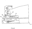
- the printer 10 can be supplied selectively with sheets 12 contained either in a main cassette 14 located inside the printer 10, or in an auxiliary cassette 15 (Fig. 4) arranged underneath the printer 10 and enclosed in a suitable unit 17 which acts as a support for the printer.
- the sheets can also be introduced by hand through a slot 18 in the left-hand side (Fig. 1) of the printer 10.
- the printer 10 comprises a developer unit DU of known type for developing, by means of a toner, the information supplied by a logical processing unit LU and transmitted to the developer unit DU by means of a laser beam LR emitted by a laser generator LG.
- the developed information is transferred to each sheet in a transfer station TS facing the developer unit DU.
- the sheet 12 runs through a fixing station FU formed by two fusing rolls 80, 81 which fix the toner particles to the sheet by heat.
- the sheet is advanced along guides 83 and then transported by rolls R into a delivery tray T at the top of the printer.
- the cassette 14 can be taken out for refilling with fresh sheets through an opening 22 on the left in Fig. 1 after opening a door 23.
- the sheets 12 are taken from the cassette 14 one at a time by means of a clockwise rotating sheet separator roll 24 interacting with a friction block 25 to block the path of second sheets that may be stuck to the required sheet 12.
- the roll 24 is mounted on an auxiliary frame 26, hinged to the structure of the printer at a point 27.
- the frame 26 can be swung up in the direction of the arrow 28, to allow the cassette 14 to be taken out.
- the sheet 12 pushed by the sheet separator roll 24 enters a first channel 30 that curves upwards towards a pair of register rolls 32 and 34 lying a short distance ahead of the developer unit DU, in the direction of advance of the sheet.
- the roll 32 is covered with a soft rubber sheet 35, while the roll 34 is of ground and polished steel.
- the rolls 32 and 34 are pressed against each other to define a registration or contact zone into which the front edge of a sheet is introduced in order correctly to align the sheet with respect to the direction of advance.
- the rolls 32 and 34 are normally stationary, but after a sheet has been introduced into the registration zone, they are rotated in order to pass the sheet towards the developer unit DU.
- the sheet 12′ When information is to be printed on a sheet 12′ inserted manually into the slot 18, the sheet 12′ is pushed manually against a pair of rotatable rolls 36, 37 that press against each other.
- the roll 36 is started by its own electric motor 38, while the roll 37 is idle.
- a sensor 40 is placed immediately before the point of contact of the rolls 36, 37 so as to signal the presence of the sheet 12′ to a logic unit LCU which controls all the operations performed by the printer 10.
- the unit LCU On a signal from the sensor 40, first starts the motor 38 for a short time so that the sheet 12′ is drawn a short way in, for example 20 mm, past the point of contact of the rolls 36, 37. The motor 38 is then stopped in order to hold the sheet 12′ still until the operator presses a button (not shown) to start the print cycle.
- the sheet 12′ does not need supporting either by the operator or by a projecting bracket, and the absence of such a bracket enables the size of the printer to be reduced.
- the motor 38 starts again and forwards the sheet 12′ to the register rolls 32, 34 through a second channel 44 that curves upwards towards the rolls 32, 34.
- the sheets 12 ⁇ which it contains, and which may be of a different format from those in the main cassette 14 are forwarded to the register rolls 32, 34 by a sheet separator roll 45 and by a pair 47 of forwarding rolls.
- the rolls 47 push a sheet 12 ⁇ along a third channel 50 (Fig. 1) delimited by a guide 51 and by the outer surface of a projection 52 of the cassette 14.
- the third channel 50 joins up with the second channel 44 downstream of the roll 36.
- the first and second channels arrive from two substantially opposite directions and join up in a single channel 54 leading to the zone of contact of the rolls 32, 34 in a direction substantially perpendicular to the direction of the first and second channels.
- the channel 54 (Fig. 2) is delimited by two end portions 55 and 56 of two walls or guides 57 and 58 respectively delimiting the first channel 30 and the second channel 44.
- the channels 30 and 44 are in turn separated by a part 60 of substantially triangular cross-section and having a vertex 62 in the lower part 63 of the channel 54.
- the part 60 delimits the channel 30 with a curved wall 64 which encourages the front edge 65 of a sheet 12 pushed by the sheet separator roll 24 to slide toward the channel 54.
- the block 25 is moved angularly in the direction of rotation of the roll 24 by an angle " ⁇ " of approximately 25° in such a way that the sheet 12 slides up the wall 64 with an incidence of less than 40°.
- the sheet then moves up the channel 30 guided by a curved projection 48 from the frame 26 and by the wall 57 and so enters the channel 54.
- the channel 54 is directed towards the steel roll 34.
- the front edge of the sheet were to touch the rubber roll 32 before reaching the registration or contact zone between the rolls 32 and 34, the sheet could misalign itself with the direction of advance and so bring about a jam.
- the front edge of the sheet touches the steel roll first, the sheet slides on its surface and feeds itself exactly into the registration zone between the rolls 32 and 34. In this way the sheet aligns itself correctly with respect to the direction of advance with a further push from the sheet separator roll 24.
- the wall 56 is inclined towards the steel roll 34 in order that an imaginary projection 70 of the internal surface 71 passes at a distance "b" from the contact or registration zone between the rolls 32, 34.
- the distance “b” is between 1 and 2 mm and is measured along the radius "R" of the roll 34 passing through the registration zone.
- the walls 55 and 56 may be parallel with each other, but preferably converge upwards at an angle of convergence " ⁇ " of between 4° and 6°, with a gap between them forming an exit slot 74 whose width is between 0.8 and 1.2 mm.
- the distance "c" between the vertex 62 of the part 60 and the straight line joining the axes A1 and A2 of the rolls 32 and 34 should be between 13 and 18 mm, while the length "l” of the channel 54 should be not less than 8 mm. In every case it is preferable for the distance "d" between the edge 56′ of the wall 56 and the roll 34 to be not less than 1.5 mm.
- the rolls 36, 37 (Fig. 2) are arranged so as to push the sheet 12′ in an upwardly inclined direction at an angle " ⁇ " of approximately 15°, so that the front edge 77 slides without sticking over the wall 78 of the part 60.
- the rolls 36, 37 push the sheet 12′ along the wall 78, through the channel 54 and finally up against the steel rolls 34.
- the front edge 77 of the sheet 12′ feeds itself between the stationary rolls 32 and 34, where it is correctly positioned by the thrust from the rolls 36, 37 in the same way as described for the sheet 12.
- the toner particles transferred in the station TS (Fig. 1) onto one side of the sheet 12 are fixed to the paper by heat by means of two rotating rolls 80 and 81 pressing against each other, between which the sheet 12 is passed.
- the roll 80 is of rubber and comes into contact with the back of the sheet.
- the roll 81 is of Teflon-coated metal (M.R.) and is heated to approximately 180°C.
- Sheets emerging from the fixing station FU are then forwarded by guides 83 and rolls R to the delivery tray T.
Landscapes
- Engineering & Computer Science (AREA)
- Mechanical Engineering (AREA)
- Registering Or Overturning Sheets (AREA)
- Auxiliary Devices For And Details Of Packaging Control (AREA)
Applications Claiming Priority (2)
| Application Number | Priority Date | Filing Date | Title |
|---|---|---|---|
| IT6783790 | 1990-10-30 | ||
| IT67837A IT1241307B (it) | 1990-10-30 | 1990-10-30 | Dispositivo per il trasporto e l'allineamento di fogli |
Publications (1)
| Publication Number | Publication Date |
|---|---|
| EP0485098A1 true EP0485098A1 (fr) | 1992-05-13 |
Family
ID=11305685
Family Applications (1)
| Application Number | Title | Priority Date | Filing Date |
|---|---|---|---|
| EP91309955A Withdrawn EP0485098A1 (fr) | 1990-10-30 | 1991-10-29 | Appareil de transport et de l'alignement de feuilles |
Country Status (2)
| Country | Link |
|---|---|
| EP (1) | EP0485098A1 (fr) |
| IT (1) | IT1241307B (fr) |
Cited By (4)
| Publication number | Priority date | Publication date | Assignee | Title |
|---|---|---|---|---|
| EP0650843A3 (fr) * | 1993-10-29 | 1995-07-26 | Hewlett Packard Co | Imprimante à fonctions multiples avec une trajectoire commune de sortie et d'alimentation. |
| WO2006000297A1 (fr) * | 2004-06-28 | 2006-01-05 | Eastman Kodak Company | Dispositif de manipulation pour support d'impression |
| US20090185846A1 (en) * | 2008-01-22 | 2009-07-23 | Ricoh Company, Ltd. | Sheet transfer apparatus and image forming apparatus |
| JP2023060474A (ja) * | 2021-10-18 | 2023-04-28 | セイコーエプソン株式会社 | 媒体搬送装置及び記録装置 |
Citations (3)
| Publication number | Priority date | Publication date | Assignee | Title |
|---|---|---|---|---|
| US4403851A (en) * | 1979-03-09 | 1983-09-13 | Ricoh Company, Ltd. | Electrostatic copying machine comprising improved arrangement of operating units |
| DE3317910A1 (de) * | 1982-05-31 | 1983-12-01 | Tokyo Shibaura Denki K.K., Kawasaki | Papierfoerdervorrichtung |
| EP0367201A2 (fr) * | 1988-10-31 | 1990-05-09 | Canon Kabushiki Kaisha | Dispositif d'alimentation de feuilles |
-
1990
- 1990-10-30 IT IT67837A patent/IT1241307B/it active IP Right Grant
-
1991
- 1991-10-29 EP EP91309955A patent/EP0485098A1/fr not_active Withdrawn
Patent Citations (3)
| Publication number | Priority date | Publication date | Assignee | Title |
|---|---|---|---|---|
| US4403851A (en) * | 1979-03-09 | 1983-09-13 | Ricoh Company, Ltd. | Electrostatic copying machine comprising improved arrangement of operating units |
| DE3317910A1 (de) * | 1982-05-31 | 1983-12-01 | Tokyo Shibaura Denki K.K., Kawasaki | Papierfoerdervorrichtung |
| EP0367201A2 (fr) * | 1988-10-31 | 1990-05-09 | Canon Kabushiki Kaisha | Dispositif d'alimentation de feuilles |
Non-Patent Citations (5)
| Title |
|---|
| PATENT ABSTRACTS OF JAPAN vol. 12, no. 121 (M-686)(2968) 15 April 1988 & JP-A-62 249 842 ( RISO KAGAKU CORP. ) 30 October 1987 * |
| PATENT ABSTRACTS OF JAPAN vol. 12, no. 260 (M-720)(3107) 21 July 1988 & JP-A-63 041 338 ( CANON INC. ) 22 February 1988 * |
| PATENT ABSTRACTS OF JAPAN vol. 12, no. 31 (M-663)(2878) 29 January 1988 & JP-A-62 185 653 ( HITACHI LTD ) 14 August 1987 * |
| PATENT ABSTRACTS OF JAPAN vol. 14, no. 351 (M-1003)(4294) 30 July 1990 & JP-A-2 123 042 ( CANON INC ) 10 May 1990 * |
| PATENT ABSTRACTS OF JAPAN vol. 9, no. 245 (M-418)(1968) 2 October 1985 & JP-A-60 097 150 ( TOSHIBA K.K. ) 30 May 1985 * |
Cited By (5)
| Publication number | Priority date | Publication date | Assignee | Title |
|---|---|---|---|---|
| EP0650843A3 (fr) * | 1993-10-29 | 1995-07-26 | Hewlett Packard Co | Imprimante à fonctions multiples avec une trajectoire commune de sortie et d'alimentation. |
| WO2006000297A1 (fr) * | 2004-06-28 | 2006-01-05 | Eastman Kodak Company | Dispositif de manipulation pour support d'impression |
| US20090185846A1 (en) * | 2008-01-22 | 2009-07-23 | Ricoh Company, Ltd. | Sheet transfer apparatus and image forming apparatus |
| US9207617B2 (en) * | 2008-01-22 | 2015-12-08 | Ricoh Company, Ltd. | Sheet transfer apparatus and image forming apparatus |
| JP2023060474A (ja) * | 2021-10-18 | 2023-04-28 | セイコーエプソン株式会社 | 媒体搬送装置及び記録装置 |
Also Published As
| Publication number | Publication date |
|---|---|
| IT9067837A0 (it) | 1990-10-30 |
| IT1241307B (it) | 1994-01-10 |
| IT9067837A1 (it) | 1992-04-30 |
Similar Documents
| Publication | Publication Date | Title |
|---|---|---|
| US4639125A (en) | Automatic duplex copying type copying apparatus | |
| EP0485098A1 (fr) | Appareil de transport et de l'alignement de feuilles | |
| EP1783561B1 (fr) | Unité de transport et refroidissement des feuilles pour appareil de formation d'image | |
| JP2561666B2 (ja) | 画像形成装置 | |
| JP2821011B2 (ja) | 原稿自動給送装置 | |
| CN119630537A (zh) | 图像形成装置 | |
| JP2803674B2 (ja) | 画像形成装置 | |
| JPH0710324A (ja) | 複写機等の用紙の搬送及び整列装置 | |
| JPH07128921A (ja) | デュプレックスユニット | |
| JP2002211789A (ja) | 画像形成装置 | |
| JP2602572B2 (ja) | シート排出装置 | |
| US5483315A (en) | Apparatus for wet processing photographic sheets | |
| JP2821009B2 (ja) | 原稿自動給送装置 | |
| JP2575700B2 (ja) | 原稿自動搬送装置 | |
| JP2505708Y2 (ja) | 用紙搬送路切換機構 | |
| JPH10109447A (ja) | 両面印刷装置 | |
| JP2001097622A (ja) | 画像形成装置 | |
| JP2638958B2 (ja) | 用紙搬送装置 | |
| JPS61130161A (ja) | 用紙搬送路用分岐装置 | |
| JP3113640B2 (ja) | 用紙搬送装置 | |
| JP3178851B2 (ja) | 両面画像形成装置 | |
| JP2833234B2 (ja) | 用紙反転装置 | |
| JP2858187B2 (ja) | シート材搬送装置 | |
| JPH0228444A (ja) | シート搬送装置 | |
| JPH10207142A (ja) | 循環型原稿搬送装置 |
Legal Events
| Date | Code | Title | Description |
|---|---|---|---|
| PUAI | Public reference made under article 153(3) epc to a published international application that has entered the european phase |
Free format text: ORIGINAL CODE: 0009012 |
|
| AK | Designated contracting states |
Kind code of ref document: A1 Designated state(s): DE FR GB NL |
|
| 17P | Request for examination filed |
Effective date: 19921009 |
|
| 17Q | First examination report despatched |
Effective date: 19940824 |
|
| STAA | Information on the status of an ep patent application or granted ep patent |
Free format text: STATUS: THE APPLICATION IS DEEMED TO BE WITHDRAWN |
|
| 18D | Application deemed to be withdrawn |
Effective date: 19950104 |