EP0485183A2 - Hochleistungsmikrowellenverstärker mit Unterdrückung von Intermodulationsprodukten - Google Patents
Hochleistungsmikrowellenverstärker mit Unterdrückung von Intermodulationsprodukten Download PDFInfo
- Publication number
- EP0485183A2 EP0485183A2 EP91310239A EP91310239A EP0485183A2 EP 0485183 A2 EP0485183 A2 EP 0485183A2 EP 91310239 A EP91310239 A EP 91310239A EP 91310239 A EP91310239 A EP 91310239A EP 0485183 A2 EP0485183 A2 EP 0485183A2
- Authority
- EP
- European Patent Office
- Prior art keywords
- signal
- error
- input signal
- amplifier
- amplified
- Prior art date
- Legal status (The legal status is an assumption and is not a legal conclusion. Google has not performed a legal analysis and makes no representation as to the accuracy of the status listed.)
- Withdrawn
Links
- 230000001629 suppression Effects 0.000 title abstract description 5
- 230000003466 anti-cipated effect Effects 0.000 claims description 7
- 230000003362 replicative effect Effects 0.000 claims 6
- 230000000903 blocking effect Effects 0.000 claims 1
- 230000008878 coupling Effects 0.000 description 5
- 238000010168 coupling process Methods 0.000 description 5
- 238000005859 coupling reaction Methods 0.000 description 5
- 238000013461 design Methods 0.000 description 3
- 238000010586 diagram Methods 0.000 description 2
- 238000010276 construction Methods 0.000 description 1
- 230000009977 dual effect Effects 0.000 description 1
- 230000000694 effects Effects 0.000 description 1
- 238000002474 experimental method Methods 0.000 description 1
- 238000004519 manufacturing process Methods 0.000 description 1
- 238000000034 method Methods 0.000 description 1
- 238000012986 modification Methods 0.000 description 1
- 230000004048 modification Effects 0.000 description 1
- 238000005457 optimization Methods 0.000 description 1
- 238000005549 size reduction Methods 0.000 description 1
- 238000011144 upstream manufacturing Methods 0.000 description 1
- 229910000859 α-Fe Inorganic materials 0.000 description 1
Images

Classifications
-
- H—ELECTRICITY
- H03—ELECTRONIC CIRCUITRY
- H03F—AMPLIFIERS
- H03F1/00—Details of amplifiers with only discharge tubes, only semiconductor devices or only unspecified devices as amplifying elements
- H03F1/32—Modifications of amplifiers to reduce non-linear distortion
- H03F1/3223—Modifications of amplifiers to reduce non-linear distortion using feed-forward
- H03F1/3229—Modifications of amplifiers to reduce non-linear distortion using feed-forward using a loop for error extraction and another loop for error subtraction
-
- H—ELECTRICITY
- H03—ELECTRONIC CIRCUITRY
- H03F—AMPLIFIERS
- H03F2201/00—Indexing scheme relating to details of amplifiers with only discharge tubes, only semiconductor devices or only unspecified devices as amplifying elements covered by H03F1/00
- H03F2201/32—Indexing scheme relating to modifications of amplifiers to reduce non-linear distortion
- H03F2201/3218—Indexing scheme relating to modifications of amplifiers to reduce non-linear distortion the main amplifier or error amplifier being a feedforward amplifier
Definitions
- the present invention relates to a low distortion, feed-forward microwave amplifier apparatus including an out-of-band intermodulation product suppression arrangement which enables the amplifier to operate with increased power and efficiency.
- Feed-forward techniques are finding increasing use in a variety of microwave communications systems.
- a particular application in which feed-forward amplifiers are especially useful is in multichannel amplitude modulated link (AML) transmitters for community antenna television (CATV) systems.
- AML amplitude modulated link
- CATV community antenna television
- Typical feed-forward amplifier arrangements are designed to cancel distortion introduced by a main power amplifier. Samples of the signal being processed are obtained before and after the main amplifier, and are compared to obtain an error signal. The error signal is amplified in an auxiliary amplifier and combined with the distortion-containing signal from the main amplifier such that cancellation of the distortion components occurs. An additional distortion cancellation stage may be added when improved performance is desired.
- the basic principles of the feed-forward amplifier arrangement are presented in a paper entitled "A Microwave Feed-Forward Experiment", by H. Seidel, in the Bell System Technical Journal, vol. 50, no. 9, Nov. 1971, pp. 2879-2916.
- FIG. 1 A practical feed-forward microwave amplifier apparatus is disclosed by the present inventor in U.S. Patent no. 4,782,307, entitled “FEED-FORWARD MICROWAVE AMPLIFIER ARRANGEMENT WITH FERRITE TEMPERATURE COMPENSATION", issued Nov. 1, 1988 and assigned to Hughes Aircraft Company, the assignee of the present invention.
- the basic arrangement of the amplifier is illustrated in FIG. 1.
- the apparatus is generally designated as 10, and includes a four port directional coupler 12 for receiving a microwave input signal IN at an input port 12b thereof.
- the input signal IN passes through the coupler 12 to an output port 12d thereof, and further through a variable phase shifter 14 to an input port 16b of a second directional coupler 16.
- the input signal IN also passes through the coupler 12 to an output port 12c thereof, and further through a variable attenuator 18 to the input of a main power amplifier 20.
- the coupler 12 has another input port 12a which is connected to a termination 22.
- the output of the amplifier 20 is connected to an input port 16a of the directional coupler 16.
- the output signal from the amplifier 20 passes through the directional coupler 16 to an output port 16c thereof with negligible attenuation, and through a variable phase shifter 24 to an input port 26a of a third directional coupler 26.
- the output signal from the amplifier 20 also passes through the coupler 16 to an output port 16d thereof, and further through a variable attenuator 28 and an auxiliary or error amplifier 30 to an input port 26b of the coupler 26.
- the apparatus 10 provides an output signal OUT with amplified power at an output port 26c of the coupler 26.
- the coupler 26 has another output port 26d which is connected to a termination 32.
- the output signal from the phase shifter 24 passes through the coupler 26 to the output port 26c with small attenuation, while the output signal from the amplifier 30 passes through the coupler 26 to the output port 26c with predetermined attenuation.
- the directional couplers 12, 16 and 26 may be of conventional construction, with the desired signal attenuation determined by the coupling ratio.
- the gain of the feedforward amplifier is equal to the coupling ratio of the coupler 16, less the loss between 12b and 16b and the loss between 16c and 26c.
- the coupling ratios of the couplers 12 and 16 are selected, and the variable attenuator 18 adjusted, such that the signal attenuation from the input port 12b of the coupler 12 to the output port 16d of the coupler 16, through the attenuator 18, amplifier 20, and coupler 16, is equal to the attenuation from the input port 12b of the coupler 12 to the output port 16d of the coupler 16, through the phase shifter 14 and coupler 16.
- the coupling ratios of the couplers 16 and 26 are selected, and the variable attenuator 28 adjusted, such that the signal attenuation from the input port 16a of the coupler 16 to the output port 26c of the coupler 26 (through the attenuator 28, amplifier 30, and coupler 26) is equal to the signal attenuation from the input port 16a of the coupler 16 to the output port 26c of the coupler 26 (through the phase shifter 24 and coupler 26).
- the directional coupler 12 samples the input signal IN and feeds a replica of the input signal along the output port 12d to the variable phase shifter 14, which is adjusted to cancel the signal at 16d which proceeds through 12c.
- the phase shifter 14 and directional coupler 16 in combination constitute a first comparator or subtractor 34 which subtracts the replica signal from the amplified version of the input signal IN which is produced or output at the output of the main power amplifier 20. More specifically, the amplified input signal and inverted replica signal are combined in the directional coupler 16. Due to the phase delay and resulting logical inversion of the replica signal, the signal combination in the coupler 16 results in the replica signal being subtracted from the amplified input signal.
- the amplified input signal appearing at the input port 16a will include distortions introduced by the amplifier 20.
- the purpose of the feed-forward arrangement is to eliminate these distortions by cancellation.
- the amplified input signal passes through the output port 16c of the coupler 16 to the phase shifter 24 with the distortions unaffected.
- the inverted replica signal will be subtracted from the amplified input signal in the branch of the coupler 16 terminating at the output port 16d, such that the remaining signal at the output port 16d ideally consists of only the distortions.
- the signal passing from the output port 16d of the coupler 16 through the attenuator 28 to the error amplifier 30 may be considered as an error signal, since it consists of the distortions or errors introduced into the input signal in the main power amplifier 20.
- the error signal is amplified in the amplifier 30, and applied to the input port 26b of the coupler 26.
- the phase shifter 24 and directional coupler 26 in combination constitute a second comparator or subtractor 36 which subtracts the error signal from the amplified and distorted input signal. More specifically, the amplified input signal and error signal are combined in the directional coupler 26. Due to the phase delay and resulting logical inversion of the amplified input signal in the phase shifter 24, the signal combination in the coupler 26 results in the error signal being subtracted from the amplified input signal.
- Microwave systems are expensive, and subject to thermal and mechanical constraints. It is therefore desirable to obtain the highest level of efficiency from each system component.
- Attempts to optimize the conventional feed-forward amplifier arrangement include providing the error amplifier with a lower power handling capability than the main power amplifier, which is therefore less expensive. This is possible since the amplified error signal has substantially lower power than the amplified input signal. Further attempts at optimization include driving the main power amplifier at as close to its saturation level as possible in order to maximize the output power.
- the error amplifier introduces distortions of its own into the error signal when the main amplifier is driven to a very high level such that the associated error signal becomes very large. This effect can become the performance limitation, particularly in feedforward amplifiers utilizing dual cancellation stages.
- the present invention overcomes the limitations inherent in the conventional feed-forward amplifier design by exploiting the realization that the secondary distortions introduced in the error amplifier at high drive power levels partially result from the generation of out-of-band intermodulation products in the main power amplifier.
- the input signal will be a multiplexed CATV signal consisting of, for example 80 channels within a bandwidth of 12.7 to 13.2 GHz.
- the signals in the individual channels mix with each other to produce high order intermodulation products which are outside the bandwidth of the input signal.
- these intermodulation products are applied to the error amplifier along with the in-band error signal.
- the out-of-band intermodulation products have significant power.
- the error amplifier will be overdriven and introduce additional distortions into the error signal.
- the out-of-band intermodulation products thereby impose an undesired burden on the error amplifier, especially at high drive power levels, which limits the size reduction of the error amplifier and maximum drive level of the main power amplifier.
- the present invention overcomes the problem created by these out-of-band intermodulation products by preventing them from being applied to the error amplifier. More specifically, a replica of a microwave input signal is subtracted from an amplified version of the input signal produced by a main power amplifier to produce an error signal corresponding to distortions introduced into the input signal by the power amplifier which are within the bandwidth of the input signal. The error signal is amplified by an error amplifier, and subtracted from the amplified input signal to produce an output signal in which the distortions have been canceled.
- a bandpass filter is provided between the power amplifier and the error amplifier to suppress or block intermodulation products generated in the power amplifier which are outside the bandwidth of the input signal and which could overload the error amplifier and thus generate further distortion. Suppression of the out-of-band intermodulation products enables operation of the power amplifier very close to its saturation limit with high efficiency.
- One or more additional error cancellation branches may be provided to produce further reduction of distortion, and may include additional bandpass filters.
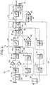
- FIG. 2 A feed-forward amplifier apparatus embodying the present invention is illustrated in FIG. 2, and generally designated as 50.
- the apparatus 50 includes the elements of the conventional apparatus 10 illustrated in FIG. 1, which are designated by the same reference numerals.
- the amplifier 20 may be replaced by two amplifiers 52a and 52b connected in parallel, with each amplifier 52a and 52b having the same power handling capability as the amplifier 20 shown in FIG. 1.
- the apparatus 50 thereby has twice the power handling capability of the apparatus 10.
- the two amplifiers 52a and 52b may be replaced with a single amplifier having higher, for example twice, the power handling capability of each individual amplifier 52a and 52b, although not specifically illustrated.
- the error amplifiers 30 and 68 may have a power handling capability which is lower than that of the combined main power amplifiers 52a and 52b, for example one-half thereof.
- the amplifiers 52a, 52b, 30 and 68 may be identical units, thereby simplifying the manufacture of the apparatus 50 by reducing the number of different components which must be provided.
- a bandpass filter 54 is provided between the combined outputs of the main power amplifiers 52a and 52b, and the input port 16a of the coupler 16.
- the bandpass filter 54 has a bandpass which is comparable to the anticipated bandwidth of the input signal IN, and thereby removes out-of-band intermodulation products from the amplified input signal applied to the input port 16a of the coupler 16.
- the bandpass filter 54 suppresses and prevents the out-of-band intermodulation products from appearing in the output signal OUT, and further prevents the out-of-band intermodulation products from reaching and overdriving the error amplifier 30. Since the error amplifier 30 is not overdriven by the out-of-band intermodulation products, it will not introduce additional distortions into the error signal. This achieves the present goals of enabling the size of the error amplifier 30 to be reduced, and the input drive level of the amplifiers 52a and 52b to be increased.
- the bandpass of the bandpass filter 54 is selected to be comparable, and preferably substantially equal, to the bandwidth of input signal IN. Maximum performance will be attained if the bandpass filter 54 provides sharp attenuation beyond the upper and lower frequency limits of the signal bandwidth. However, the term "substantially equal” should be given considerable latitude within the scope of the present invention.
- the primary constraint on the bandpass of the filter 54 is that it include the bandwidth of the input signal IN and exclude at least the bulk of the out-of-band intermodulation products.
- the bandpass filter 54 may be of any known type which fulfills the design requirements of a particular application. Numerous types of bandpass filters which are suitable for practicing the present invention are described in detail in a textbook entitled “Microwave Filters, Impedance-Matching Networks and Coupling Structures", by G. Matthaei et al, McGraw-Hill 1964, pp. 421-724.
- the bandpass filter 54 may be a conventional obstacle-coupled waveguide cavity filter, which is a coupled resonator filter of the type described in the Matthaei reference on pages 427 to 433, designed to produce an attenuation of 8 dB at frequencies 100 MHz above and below the bandwidth of the input signal.
- the apparatus 50 may include an additional error cancellation stage or branch to further improve the performance thereof.
- the general concept of an additional error cancellation stage is known, but not with the out-of-band intermodulation product suppression feature of the present invention.
- a splitter 56 samples the input signal IN and feeds a second replica signal to a third comparator or subtractor 58 which includes a variable phase shifter 60, an attenuator 62, and a directional coupler 64.
- the phase-inverted second replica signal is applied to an input port 64b and subtracted in the coupler 64 from the once corrected input signal from the coupler 26 applied to an input port 64a to produce or output a second error signal at an output port 64d which represents residual distortions introduced in the main power amplifiers 52a and 52b, as well as any additional distortions introduced in the error amplifier 30.
- the out-of-band intermodulation products would be relatively enhanced relative to the in-band intermodulation products in the second error signal since the efficacy of the cancellation of the first error signal is typically bandwidth limited by imperfect amplitude and phase matching.
- the filter 54 is particularly useful in avoiding overload of the amplifier 68.
- the second error signal is passed through a variable attenuator 66 and second error amplifier 68 to an input port 70b of a directional coupler 70.
- the once corrected input signal is passed from an output port 64c of the coupler 64 through a phase shifter 72 to an input port 70a of the coupler 70.
- the phase shifter 72 and coupler 70 in combination constitute a fourth comparator or subtractor 74, which subtracts the second error signal from the once corrected amplified input signal to produce or output a twice corrected output signal at an output port 70c with the residual distortions removed.
- the attenuator 66 is adjusted so as to attain equal attenuation of the once corrected input signal and the second error signal. Further illustrated is a termination 76 connected to an output port 70d of the coupler 70. Although not illustrated, one or more additional distortion cancellation stages may be added to the configuration of FIG. 2.
- the performance of the apparatus 50 may be improved by providing an additional bandpass filter 78 and/or a bandpass filter 80 to ensure a good phase and amplitude match over the full signal band to better replicate the intermodulation-free portion of the amplified and bandpassed signal at 16a.
- the bandpass filters 78 and 80 should be of the same design as the filter 54, connected in circuit downstream of the phase shifters 14 and 60 as illustrated. Although not shown, the filters 78 and 80 may alternatively be connected upstream of the respective phase shifters 14 and 60.
Landscapes
- Physics & Mathematics (AREA)
- Nonlinear Science (AREA)
- Engineering & Computer Science (AREA)
- Power Engineering (AREA)
- Amplifiers (AREA)
Applications Claiming Priority (2)
| Application Number | Priority Date | Filing Date | Title |
|---|---|---|---|
| US612166 | 1984-05-21 | ||
| US07/612,166 US5117197A (en) | 1990-11-09 | 1990-11-09 | High-power feed-forward microwave amplifier apparatus with out-of-band intermodulation product suppression |
Publications (2)
| Publication Number | Publication Date |
|---|---|
| EP0485183A2 true EP0485183A2 (de) | 1992-05-13 |
| EP0485183A3 EP0485183A3 (en) | 1992-12-16 |
Family
ID=24452007
Family Applications (1)
| Application Number | Title | Priority Date | Filing Date |
|---|---|---|---|
| EP19910310239 Withdrawn EP0485183A3 (en) | 1990-11-09 | 1991-11-05 | High power feed-forward microwave amplifier with out-of-band intermodulation product suppression |
Country Status (2)
| Country | Link |
|---|---|
| US (1) | US5117197A (de) |
| EP (1) | EP0485183A3 (de) |
Cited By (7)
| Publication number | Priority date | Publication date | Assignee | Title |
|---|---|---|---|---|
| WO1996019864A1 (en) * | 1994-12-21 | 1996-06-27 | University Of Bristol | Receiver circuit |
| WO1999027645A1 (en) * | 1997-11-21 | 1999-06-03 | Telefonaktiebolaget Lm Ericsson (Publ) | An amplifier and a method of power amplification |
| EP0797868A4 (de) * | 1995-10-17 | 1999-08-04 | Motorola Inc | Verstärkerschaltung für kodfrequenzsystem |
| EP1003278A3 (de) * | 1998-11-18 | 2001-10-10 | Lucent Technologies Inc. | Geschachteltes vorwärtsgekoppeltes System zur Reduzierung von Verzerrungen |
| EP1315288A1 (de) * | 2001-09-27 | 2003-05-28 | Hitachi Kokusai Electric Inc. | Verstärker mit Verzerrungskompensation |
| EP1030441A3 (de) * | 1999-02-16 | 2004-03-17 | Matsushita Electric Industrial Co., Ltd. | Vorwärtskopplungsverstärker |
| US20230080916A1 (en) * | 2021-09-09 | 2023-03-16 | Hughes Network Systems, Llc | Q-band block down converter |
Families Citing this family (16)
| Publication number | Priority date | Publication date | Assignee | Title |
|---|---|---|---|---|
| US5304945A (en) * | 1993-04-19 | 1994-04-19 | At&T Bell Laboratories | Low-distortion feed-forward amplifier |
| US5455537A (en) * | 1994-08-19 | 1995-10-03 | Radio Frequency Systems, Inc. | Feed forward amplifier |
| US5489875A (en) * | 1994-09-21 | 1996-02-06 | Simon Fraser University | Adaptive feedforward linearizer for RF power amplifiers |
| JP3360464B2 (ja) * | 1995-02-13 | 2002-12-24 | 松下電器産業株式会社 | フィードフォワード増幅器 |
| US5471164A (en) * | 1995-02-23 | 1995-11-28 | Penny; James R. | Microwave amplifier linearizer |
| US5606286A (en) * | 1995-07-27 | 1997-02-25 | Bains; Devendar S. | Predistortion linearization |
| US5619168A (en) * | 1995-08-07 | 1997-04-08 | Lucent Technologies Inc. | Distortion creation and reduction circuit |
| US5742201A (en) * | 1996-01-30 | 1998-04-21 | Spectrian | Polar envelope correction mechanism for enhancing linearity of RF/microwave power amplifier |
| US5892397A (en) * | 1996-03-29 | 1999-04-06 | Spectrian | Adaptive compensation of RF amplifier distortion by injecting predistortion signal derived from respectively different functions of input signal amplitude |
| KR100362925B1 (ko) * | 1999-03-31 | 2002-11-29 | 가부시키가이샤 엔.티.티.도코모 | 피드포워드 증폭기 |
| KR100426618B1 (ko) * | 2001-12-13 | 2004-04-13 | 한국전자통신연구원 | 수동 혼변조 제거장치 및 그 방법 |
| US6794938B2 (en) | 2002-03-19 | 2004-09-21 | The University Of North Carolina At Charlotte | Method and apparatus for cancellation of third order intermodulation distortion and other nonlinearities |
| US6657490B2 (en) * | 2002-03-28 | 2003-12-02 | Motorola, Inc. | Feedforward signal generation for combined amplifiers |
| US6744314B2 (en) * | 2002-06-20 | 2004-06-01 | Harris Corporation | Wideband power amplifier linearization technique |
| US8583049B2 (en) * | 2009-09-08 | 2013-11-12 | Bae Systems Information And Electronic Systems Integration Inc. | Self-optimizing integrated RF converter |
| US9641138B2 (en) | 2015-04-09 | 2017-05-02 | Analog Devices, Inc. | Multipath feedforward band pass amplifier |
Family Cites Families (4)
| Publication number | Priority date | Publication date | Assignee | Title |
|---|---|---|---|---|
| US3471798A (en) * | 1967-12-26 | 1969-10-07 | Bell Telephone Labor Inc | Feed-forward amplifier |
| US4394624A (en) * | 1981-08-07 | 1983-07-19 | The United States Of America As Represented By The Secretary Of The Navy | Channelized feed-forward system |
| US4617522A (en) * | 1984-03-20 | 1986-10-14 | General Instrument Corporation | Temperature regulated feedforward amplifier |
| US4560945A (en) * | 1984-09-04 | 1985-12-24 | Westinghouse Electric Corp. | Adaptive feedforward cancellation technique that is effective in reducing amplifier harmonic distortion products as well as intermodulation distortion products |
-
1990
- 1990-11-09 US US07/612,166 patent/US5117197A/en not_active Expired - Fee Related
-
1991
- 1991-11-05 EP EP19910310239 patent/EP0485183A3/en not_active Withdrawn
Cited By (14)
| Publication number | Priority date | Publication date | Assignee | Title |
|---|---|---|---|---|
| WO1996019864A1 (en) * | 1994-12-21 | 1996-06-27 | University Of Bristol | Receiver circuit |
| EP0797868A4 (de) * | 1995-10-17 | 1999-08-04 | Motorola Inc | Verstärkerschaltung für kodfrequenzsystem |
| WO1999027645A1 (en) * | 1997-11-21 | 1999-06-03 | Telefonaktiebolaget Lm Ericsson (Publ) | An amplifier and a method of power amplification |
| US6163213A (en) * | 1997-11-21 | 2000-12-19 | Telefonaktiebolget Lm Ericsson | Amplifier and a method of power amplification |
| KR100553251B1 (ko) * | 1997-11-21 | 2006-02-20 | 텔레폰악티에볼라겟엘엠에릭슨(펍) | 전력 증폭기 및 증폭 방법 |
| EP1003278A3 (de) * | 1998-11-18 | 2001-10-10 | Lucent Technologies Inc. | Geschachteltes vorwärtsgekoppeltes System zur Reduzierung von Verzerrungen |
| EP1030441A3 (de) * | 1999-02-16 | 2004-03-17 | Matsushita Electric Industrial Co., Ltd. | Vorwärtskopplungsverstärker |
| US6727751B2 (en) | 2001-09-27 | 2004-04-27 | Hitachi Kokusai Electric Inc. | Distortion compensation amplifier |
| EP1315288A1 (de) * | 2001-09-27 | 2003-05-28 | Hitachi Kokusai Electric Inc. | Verstärker mit Verzerrungskompensation |
| US20230080916A1 (en) * | 2021-09-09 | 2023-03-16 | Hughes Network Systems, Llc | Q-band block down converter |
| US11909429B2 (en) * | 2021-09-09 | 2024-02-20 | Hughes Network Systems, Llc | Q-band block down converter |
| US20240348275A1 (en) * | 2021-09-09 | 2024-10-17 | Hughes Network Systems, Llc | Q-band block down converter |
| US12237856B2 (en) | 2021-09-09 | 2025-02-25 | Hughes Network Systems, Llc | Q-band block down converter |
| US20250233606A1 (en) * | 2021-09-09 | 2025-07-17 | Hughes Network Systems, Llc | Q-band block down converter |
Also Published As
| Publication number | Publication date |
|---|---|
| US5117197A (en) | 1992-05-26 |
| EP0485183A3 (en) | 1992-12-16 |
Similar Documents
| Publication | Publication Date | Title |
|---|---|---|
| US5117197A (en) | High-power feed-forward microwave amplifier apparatus with out-of-band intermodulation product suppression | |
| US5157346A (en) | Rf wideband high power amplifier | |
| EP0411180B1 (de) | Verzerrungskorrektionsschaltung mit Vorwärtskopplung | |
| US4581595A (en) | Phase shift network with minimum amplitude ripple | |
| US4629996A (en) | Feed-forward microwave power amplifier with difference signal distortion cancellation circuit | |
| US7183847B2 (en) | Multi-band look-up table type predistorter | |
| KR19980042391A (ko) | 입력 신호 주파수에 상관없이 안정한 비선형 특성을 갖는 자동프리디스토션 조정 회로 | |
| US4595882A (en) | Phase adjusted feedforward error correction | |
| US20020130716A1 (en) | Linearization circuit and technique for a power combining network, or diplexer; especially as may use high temperature superconducting filters | |
| EP0552059B1 (de) | Leistungsverstärkervorrichtung | |
| US4258328A (en) | Feed forward microwave amplifier for communication systems | |
| US3873936A (en) | Apparatus for reducing distortion in a repeatered transmission system | |
| US4092616A (en) | Traveling wave power combining apparatus | |
| US6285252B1 (en) | Apparatus and method for broadband feedforward predistortion | |
| US4532478A (en) | Phase adjusted feedforward system utilizing a single amplitude/phase equalizer | |
| US5258722A (en) | Amplifier circuit with distortion cancellation | |
| Bennett et al. | Feedforward—An alternative approach to amplifier linearization | |
| US5363056A (en) | Circuit for linearization of amplified electronic signals | |
| EP1475887A2 (de) | Mehrtor-Verstärker mit Eingangshybridnetzwerk für digitale Quadraturbasisbandsignale | |
| GB2107540A (en) | Feedforward amplifiers | |
| KR20000035437A (ko) | 네스트된 피드포워드 왜곡 감소 시스템 | |
| US3771064A (en) | Bidirectional signal processing means | |
| US4168511A (en) | Common amplification system for video and audio frequency signals | |
| US5428314A (en) | Odd/even order distortion generator and distortion cancellation circuit | |
| US3993961A (en) | Overcompensated feedforward method and apparatus using overdistorted main amplifiers |
Legal Events
| Date | Code | Title | Description |
|---|---|---|---|
| PUAI | Public reference made under article 153(3) epc to a published international application that has entered the european phase |
Free format text: ORIGINAL CODE: 0009012 |
|
| AK | Designated contracting states |
Kind code of ref document: A2 Designated state(s): DE FR GB |
|
| PUAL | Search report despatched |
Free format text: ORIGINAL CODE: 0009013 |
|
| AK | Designated contracting states |
Kind code of ref document: A3 Designated state(s): DE FR GB |
|
| 17P | Request for examination filed |
Effective date: 19930525 |
|
| 17Q | First examination report despatched |
Effective date: 19950316 |
|
| STAA | Information on the status of an ep patent application or granted ep patent |
Free format text: STATUS: THE APPLICATION IS DEEMED TO BE WITHDRAWN |
|
| 18D | Application deemed to be withdrawn |
Effective date: 19950727 |