EP0485231A1 - Betätigungseinrichtung für ein electromagnetisches Ventil - Google Patents
Betätigungseinrichtung für ein electromagnetisches Ventil Download PDFInfo
- Publication number
- EP0485231A1 EP0485231A1 EP91310353A EP91310353A EP0485231A1 EP 0485231 A1 EP0485231 A1 EP 0485231A1 EP 91310353 A EP91310353 A EP 91310353A EP 91310353 A EP91310353 A EP 91310353A EP 0485231 A1 EP0485231 A1 EP 0485231A1
- Authority
- EP
- European Patent Office
- Prior art keywords
- valve
- magnetic pole
- driving
- supply
- secondary coils
- Prior art date
- Legal status (The legal status is an assumption and is not a legal conclusion. Google has not performed a legal analysis and makes no representation as to the accuracy of the status listed.)
- Granted
Links
Images


Classifications
-
- F—MECHANICAL ENGINEERING; LIGHTING; HEATING; WEAPONS; BLASTING
- F01—MACHINES OR ENGINES IN GENERAL; ENGINE PLANTS IN GENERAL; STEAM ENGINES
- F01L—CYCLICALLY OPERATING VALVES FOR MACHINES OR ENGINES
- F01L9/00—Valve-gear or valve arrangements actuated non-mechanically
- F01L9/20—Valve-gear or valve arrangements actuated non-mechanically by electric means
-
- F—MECHANICAL ENGINEERING; LIGHTING; HEATING; WEAPONS; BLASTING
- F01—MACHINES OR ENGINES IN GENERAL; ENGINE PLANTS IN GENERAL; STEAM ENGINES
- F01L—CYCLICALLY OPERATING VALVES FOR MACHINES OR ENGINES
- F01L9/00—Valve-gear or valve arrangements actuated non-mechanically
- F01L9/20—Valve-gear or valve arrangements actuated non-mechanically by electric means
- F01L9/21—Valve-gear or valve arrangements actuated non-mechanically by electric means actuated by solenoids
- F01L2009/2115—Moving coil actuators
Definitions
- the present invention relates to an electromagnetic force valve driving apparatus for capable of driving opening and closing a supply / exhaust valve of an engine by an electromagnetic force.
- the supply / exhaust valves adapted to always be biased in closing direction by spring are driven of their opening and closing by depressing each shaft end face of the valves through a link mechanism such as a locker arm, a pushing rod and the like from a cam surface of a cam shaft which is driven by an output shaft of an engine and is rotating synchrononsly in phase with rotation of the engine.
- An engine configuration of the opening / closing drive apparatus requires as described above a larger size engine due to provision of the cam shaft and link mechanism within the engine. Also friction resistance on driving the cam shaft and link mechanism canses provides partial dissipation of engine output, lowering effective engine-output.
- the open / close timing of the supply / exhaust valve Since the open / close timing of the supply / exhaust valve is impossible to vary easily during operation of the engine, the open / close timing of valve must be adjusted to optimize its running condition at a specific rotation speed of the engine. Accordingly when running at a rotation speed differing from the specified one, it is impossible to obtain satisfactory output and efficiency which the engine intrinsically exhibits.
- valve drive apparatuses are disclosed in the Japanese Patent Application Laid Opens No.183805 in 1983 and No.76713 in 1986, such that the valve drive apparatuses are adapted to open and close the supply / exhaust valve capable of varying the opening / closing timing thereof by means of attracting movable magnetic poles connected to the supply / exhaust valve using an electromagnetic force of magnet fixed on the engine.
- a requirement of generating very strong magnetic force results in enlarging a magnetic flux density and thus expanding a cross section of magnetic path.
- the expanded cross sections of magnetic path, or enlarge the drive apparatuses creates a problem that because an interference arises by the adjacent drive apparatuses of the supply / exhaust valves being overlapped, these adjacent drive apparatuses can not be accommodated in an engine.
- the present invention is made in the light of the problems described above, and an object of the invention is to provide an apparatus for electromagnetic force valve driving apparatus capable of generating very strong electromagnetic force even when in a narrow pitch for installation of the supply / exhaust valve and in assembling within a narrow space due to a barrier or an interfering object.
- An apparatus for driving an electromagnetic force valve in accordance with the present invention drives a supply / exhaust valve by an electromagnetic force acting between primary coil and secondary coils, the primary coil being fixed on an engine and generating magnetic flux, the secondary coils capable of reciprocating movement being connected to the supply / exhaust valve and capable of inducing current by the flux
- the invention is to provide an electromagnetic force valve driving apparatus characterized by comprising: a fixed magnetic pole which is wound with the primary coils and opposingly disposed embracing the secondary coils in the perpendicular direction to the reciprocating movement direction of the secondary coils; an air gap adjacent with a tip end of the fixed magnetic pole and provided on any position of a magnetic flux path generated from the primary coil; a movable element made of magnetic substance, and movable reciprocatingly in the air gap , to form part of the magnetic flux path, and to contain the secondary coils.
- An electromagnetic force valve driving apparatus provided with the constitution as hereinbefore described, since a fixed magnetic pole is provided opposingly embracing the primary coil, width of the perpendicular direction to the opposing direction of the fixed magnetic pole is reduced to enable installation in a narrower space and a very strong electromagnetic force is allowed to exert on the movable element in good balance.
- the present invention can provide an apparatus for driving valve by electromagnetic force capable of generating a very strong electromagnetic force even in the arrangement of the supply/ exhaust valve with narrower installation pitch or in assembling in a very narrow space due to an interfering object because the width of the perpendicular direction to the opposing direction of the fixed magnetic pole is reduced to enable installation in the narrower space. And allowing a very strong electromagnetic force to be exerted on the movable element in good balance since the fixed magnetic pole is opposingly arranged embracing the primary coil.
- Figure 1 is a block diagram showing the constitution of an electromagnetic force valve driving apparatus according to the present invention.
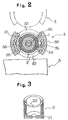
- Figure 2 is a sectional view taken along line II-II in figure 1.
- Figure 3 is a sectional perspective view of a moving element of an electromagnetic force valve driving apparatus
- Figure 4 is illustration showing magnetic flux exerting on a movable magnetic pole of an apparatus for driving an electromagnetic force valve driving apparatus according to the invention.
- Figure 1 is a block diagram showing constitution of an apparatus for driving valve by electromagnetic force according to the invention.
- Figure 2 is a sectional view taken along line II-II in figure 1.
- a supply valve and an exhaust valve are provided in an engine as hereinbefore described.
- the driving apparatus in accordance with the present invention can be applied to both of the supply valve and the exhaust valves, then hereinafter the apparatus for opening and closing the supply valve will be essentially described.
- Numeral 1 is a supply valve made of ceramic material such as silicon nitride etc which is light in weight and excellent in strength in higher temperature.
- a movable magnetic pole 11 of disk shape is connected to a shaft end of the supply valve 1.
- the movable magnetic pole 11 is formed to be thinner in thickness as the distance from its center toward peripheral portions increases.
- the area of magnetic path formed between the movable magnetic pole 11 and a fixed magnetic pole described later is set uniform from the center to the peripheral portions.
- the supply valve 1 is pivotally supported capable of freely reciprocating by a valve guide 12, and during the closing of the supply valve 1 an umbrella-shape portion of the supply valve 1 sits on a valve seat 14 to close a supply port.
- a movable element 2 as described later is connected in the vicinity of center of a shaft portion of the supply valve 1. During the time when the engine is not operated, the movable element 2 is biased in the closing direction by a spring 13 to prevent the supply valve 1 from coming down.
- Numeral 3 depicts a drive assembly.
- the upper end portion is provided with a fixed magnetic pole 31 of ring shape opposing to the lower center portion of the movable magnetic pole 11 and a fixed magnetic pole 32 of ring shape opposing to the lower face peripheral portion of the movable magnetic pole 11.
- the fixed magnetic poles 31 and 32 are concentrically disposed.
- An exciting coil 33 for exciting the magnetic poles 31 and 32 are arranged in a ring shape groove formed by the magnetic poles 31 and 32.
- the fixed magnetic pole 31 is peripherally disposed with very small space apart from the outer circumference surface of the shaft portion of the supply valve 1.
- a center magnetic pole 34 is provided extending in the lower direction of the fixed magnetic pole 31.
- the center magnetic pole 34 is formed in a cylindrical configuration and is arranged at a portion surrounding the shaft of the supply valve 1. The outer circumference of the center magnetic pole 34 is opposed to the inner circumference of the movable element 2.
- stator magnetic poles 35 In the drive assembly 3, there are provided two rows of stator magnetic poles 35 opposing each other at two positions through the outer circumference of the center magnetic pole 34 and the movable element 2, or opposing each other embracing the movable element 2.
- the stator magnetic poles 35 are provided in a plurality of stages in the reciprocating direction of the movable element 2.
- the stator magnetic poles 35 are wound with a primary coil 36 and flux density and flux direction respectively passing through the stator magnetic poles 35 are controlled at the respective stage basis.
- Figure 1 shows part of the flux flow generated from the stator magnetic poles 35 with an arrow mark.
- Numeral 4 depicts a controller comprising an input / output interface taking charge of input / output of signals, ROM storing previously program or various related maps, CPU executing computation with reference to the program stored in said ROM, RAM temporarily storing computed result or data, a control memory controlling signal flow within the controller 4, and others.
- An initial drive apparatus 41 and a speed adjustment apparatus 42 are connected to the controller 4.
- the initial drive apparatus 41 is connected to the exciting coil 33.
- the exciting coil 33 receives power and excites the fixed magnetic poles 31 and 32.
- the speed adjustment apparatus 42 is connected in each stage basis to the primary coil 36. With the speed control signals being inputted from the controller 4, the speed adjustment apparatus 42 supplies AC power of different phases in every stage of the primary coil 36 to form a travelling magnetic field by the flux passing through the stator magnetic poles 35, the travelling magnetic field being controlled of its travelling speed and direction.
- numeral 3′ depicts another supply valve provided adjacent with the supply valve 1 or the drive assembly for driving the supply valve.
- the drive assembly 3 and the drive assembly 3′ are juxtaposed so that respective lines including points where the fixed magnetic poles 35 are located may be in parallel as shown in the drawing. Thus, the installation pitch of the drive assemblies 3 and 3′ may be reduced.
- Numeral 5 depicts a barrier limiting a location in mounting the drive assembly 3. As in the drawing, the location the supply valve 1 may be neared to the barrier 5 by making the lines connecting the fixed magnetic poles 35 are parallel with the wall face of the barrier 5.
- Figure 3 is a perspective sectional view of the movable element.
- the movable element 2 is in a cup configuration or in the form of cylindrical shape with a bottom.
- the movable element 2 comprises: a core 21 made of composite material including magnetic substance powder and plastic; a plurality of secondary coils 22 with closing ring configurations held by the core 21.
- the magnetic substance powder included in the core 21 is formed of, for example, short fibre of silicon steel or fine grain of the same.
- the magnetic substance powder being kneaded with the plastic before hardening of the plastic, and resultant mixed substance is filled in the mold arranged with the second coils 22 on specified positions, to form the movable element 2.
- the movable element 2 may also be formed, alternatively, by means of heating the plastic to melt after filling into mold by mixing plastic powder of thermal plasticity with magnetic substance powder.
- the secondary coils 22 are formed of, for example, electrically conductive metallic material such as aluminium and the like having smaller specific gravity or otherwise of conductive ceramic.
- the movable element 2 thus produced has excellent magnetic permeability with light weight, therefore inertia mass of reciprocating drive system of the supply valve 1 may be greatly reduced.
- the controller 4 is always continuing to detect rotation phase of the engine and its load, a computation being made for the opening / closing timing and the lift amount of the supply valve corresponding to the engine load.
- the controller 4 outputs control signals to an initial drive apparatus 41.
- the exciting coil 33 receives power to excite the fixed magnetic poles 31 and 32.
- Figure 4 illustrates a profile where the fixed magnetic pole 31 is excited to S polarity and the magnetic pole 32 to N polarity.
- Figure 4 is an illustration of the flux exerting on a movable magnetic pole.
- arrow mark B indicates flux travelling.
- the fixed magnetic pole 32 emits the flux which travels through inside the movable magnetic pole 11 to form magnetic path continuing into the fixed magnetic pole 31. From this operation, the movable magnetic pole 11 is attracted to all the circumferences of the fixed magnetic poles 31 and 32, a very strong initial driving force may thus be produced even when the diameter of the movable magnetic pole 11 is smaller than the external diameter where the stator magnetic poles 35 are provided.
- the reciprocating movement system of the supply valve 1 has a reduced inertia mass, so that a larger acceleration is thus realized.
- the exciting coil 33 receives electric power and initially drives the supply valve 1, the supply valve is driven up to the lift amount computed as hereinbefore described.
- the supply valve 1 is adjusted of its moving speed so as to sit the supply valve 1 on the valve seat 14 using the closing timing further calculated.
- An adjustment of moving speed is performed by outputting speed control, signals to the speed adjustment apparatus 42 from the controller 4 as described above.
- the spring 14 holding the supply valve 1 at a closing state has a biasing force being set satisfactorily smaller against the electromagnetic force.
Landscapes
- Engineering & Computer Science (AREA)
- Mechanical Engineering (AREA)
- General Engineering & Computer Science (AREA)
- Valve Device For Special Equipments (AREA)
- Magnetically Actuated Valves (AREA)
- Output Control And Ontrol Of Special Type Engine (AREA)
Applications Claiming Priority (2)
| Application Number | Priority Date | Filing Date | Title |
|---|---|---|---|
| JP2303236A JPH04175408A (ja) | 1990-11-08 | 1990-11-08 | 電磁力バルブ駆動装置 |
| JP303236/90 | 1990-11-08 |
Publications (2)
| Publication Number | Publication Date |
|---|---|
| EP0485231A1 true EP0485231A1 (de) | 1992-05-13 |
| EP0485231B1 EP0485231B1 (de) | 1996-05-22 |
Family
ID=17918516
Family Applications (1)
| Application Number | Title | Priority Date | Filing Date |
|---|---|---|---|
| EP91310353A Expired - Lifetime EP0485231B1 (de) | 1990-11-08 | 1991-11-08 | Betätigungseinrichtung für ein electromagnetisches Ventil |
Country Status (4)
| Country | Link |
|---|---|
| US (1) | US5406241A (de) |
| EP (1) | EP0485231B1 (de) |
| JP (1) | JPH04175408A (de) |
| DE (1) | DE69119703T2 (de) |
Cited By (8)
| Publication number | Priority date | Publication date | Assignee | Title |
|---|---|---|---|---|
| DE19723923A1 (de) * | 1997-06-06 | 1998-12-10 | Gruendl & Hoffmann | Ventilanordnung für einen ventilgesteuerten Verbrennungsmotor |
| WO2002008579A1 (de) * | 2000-07-24 | 2002-01-31 | Compact Dynamics Gmbh | Gaswechselventilantrieb für einen ventilgesteuerten verbrennungsmotor |
| DE10035973C2 (de) * | 2000-07-24 | 2003-06-05 | Compact Dynamics Gmbh | Gaswechselventil für einen ventilgesteuerten Verbrennungsmotor |
| DE10044789C2 (de) * | 2000-09-11 | 2003-06-12 | Compact Dynamics Gmbh | Antiebsvorrichtung eines Gaswechselventils für einen ventilgesteuerten Verbrennungsmotor |
| DE10341698A1 (de) * | 2003-05-26 | 2004-12-16 | Continental Teves Ag & Co. Ohg | Ventilantrieb für ein Gaswechselventil |
| DE102005017482A1 (de) * | 2005-04-15 | 2006-11-02 | Compact Dynamics Gmbh | Gaswechselventilaktor für einen ventilgesteuerten Verbrennungsmotor |
| US7989991B2 (en) | 2005-04-15 | 2011-08-02 | Compact Dynamics, GmbH | Linear actuator |
| CN101676526B (zh) * | 2008-09-16 | 2012-01-04 | 金健 | 一种电动气门总成 |
Families Citing this family (11)
| Publication number | Priority date | Publication date | Assignee | Title |
|---|---|---|---|---|
| US5622351A (en) * | 1994-05-31 | 1997-04-22 | Daewoo Electronics Co., Ltd. | Water-supply valve of a washing machine |
| US6039014A (en) * | 1998-06-01 | 2000-03-21 | Eaton Corporation | System and method for regenerative electromagnetic engine valve actuation |
| JP2001351812A (ja) * | 2000-06-06 | 2001-12-21 | Mikuni Corp | 電磁アクチュエータ及びこれを用いた弁駆動装置並びに位置又は速度センサ |
| WO2004104380A1 (de) * | 2003-05-26 | 2004-12-02 | Continental Teves Ag & Co. Ohg | Ventilantrieb für ein gaswechselventil |
| DE102004042925A1 (de) * | 2004-09-02 | 2006-03-09 | Heinz Leiber | Federnde Aktuatorankopplung |
| DE102005017483B4 (de) * | 2005-04-15 | 2007-04-05 | Compact Dynamics Gmbh | Linearaktor in einem Elektro-Schlagwerkzeug |
| US7270093B2 (en) * | 2005-04-19 | 2007-09-18 | Len Development Services Corp. | Internal combustion engine with electronic valve actuators and control system therefor |
| US8037853B2 (en) * | 2005-04-19 | 2011-10-18 | Len Development Services Usa, Llc | Internal combustion engine with electronic valve actuators and control system therefor |
| US20070069172A1 (en) * | 2005-04-26 | 2007-03-29 | Parker-Hannifin Corporation | Magnetic repulsion actuator and method |
| US11004587B2 (en) * | 2018-07-16 | 2021-05-11 | The Florida State University Research Foundation, Inc. | Linear actuator for valve control and operating systems and methods |
| CN109854323A (zh) * | 2019-03-12 | 2019-06-07 | 北方工业大学 | 低功耗响应迅速的活塞发动机气门装置 |
Family Cites Families (11)
| Publication number | Priority date | Publication date | Assignee | Title |
|---|---|---|---|---|
| DE3307070C2 (de) * | 1983-03-01 | 1985-11-28 | FEV Forschungsgesellschaft für Energietechnik und Verbrennungsmotoren mbH, 5100 Aachen | Stelleinrichtung für ein zwischen zwei Endstellungen verstellbares Schaltelement |
| JPS61142708A (ja) * | 1984-12-15 | 1986-06-30 | Diesel Kiki Co Ltd | 電磁アクチュエ−タ |
| US4829947A (en) * | 1987-08-12 | 1989-05-16 | General Motors Corporation | Variable lift operation of bistable electromechanical poppet valve actuator |
| JP2526651B2 (ja) * | 1988-12-22 | 1996-08-21 | いすゞ自動車株式会社 | 内燃機関 |
| JPH02173306A (ja) * | 1988-12-26 | 1990-07-04 | Isuzu Motors Ltd | 電磁力駆動バルブ制御装置 |
| JP2652802B2 (ja) * | 1988-12-28 | 1997-09-10 | 株式会社いすゞセラミックス研究所 | 電磁力バルブ駆動装置 |
| JP2596459B2 (ja) * | 1989-03-30 | 1997-04-02 | 株式会社いすゞセラミックス研究所 | バルブの電磁力駆動装置 |
| JP2610187B2 (ja) * | 1989-04-28 | 1997-05-14 | 株式会社いすゞセラミックス研究所 | バルブの駆動装置 |
| JP2709737B2 (ja) * | 1989-09-01 | 1998-02-04 | 株式会社いすゞセラミックス研究所 | 電磁力バルブ駆動装置 |
| JP2707141B2 (ja) * | 1989-09-01 | 1998-01-28 | 株式会社いすゞセラミックス研究所 | 電磁力バルブ駆動装置 |
| JP3040784B2 (ja) * | 1989-09-01 | 2000-05-15 | 株式会社いすゞセラミックス研究所 | 誘導式電磁力バルブ駆動装置 |
-
1990
- 1990-11-08 JP JP2303236A patent/JPH04175408A/ja active Pending
-
1991
- 1991-11-08 EP EP91310353A patent/EP0485231B1/de not_active Expired - Lifetime
- 1991-11-08 DE DE69119703T patent/DE69119703T2/de not_active Expired - Fee Related
-
1993
- 1993-05-27 US US08/068,612 patent/US5406241A/en not_active Expired - Fee Related
Non-Patent Citations (4)
| Title |
|---|
| PATENT ABSTRACTS OF JAPAN vol. 14, no. 436 (M-102)18 September 1990 & JP-A-2 173 306 ( ISUZU MOTORS LTD ) 4 July 1990 * |
| PATENT ABSTRACTS OF JAPAN vol. 15, no. 272 (M-113)10 July 1991 & JP-A-3 092 517 ( ISUZU CERAMICS KENKYUSHO KK ) 17 April 1991 * |
| PATENT ABSTRACTS OF JAPAN vol. 15, no. 272 (M-113)10 July 1991 & JP-A-3 092 518 ( ISUZU CERAMICS KENKYUSHO KK ) 17 April 1991 * |
| PATENT ABSTRACTS OF JAPAN vol. 15, no. 272 (M-113)10 July 1991 & JP-A-3 092 520 ( ISUZU CERAMICS KENKYUSHO KK ) 17 April 1991 * |
Cited By (15)
| Publication number | Priority date | Publication date | Assignee | Title |
|---|---|---|---|---|
| DE19723923A1 (de) * | 1997-06-06 | 1998-12-10 | Gruendl & Hoffmann | Ventilanordnung für einen ventilgesteuerten Verbrennungsmotor |
| WO1998055741A1 (de) * | 1997-06-06 | 1998-12-10 | Gründl und Hoffmann GmbH Gesellschaft für elektrotechnische Entwicklungen | Ventilanordnung für einen ventilgesteuerten verbrennungsmotor |
| DE19723923C2 (de) * | 1997-06-06 | 2000-06-21 | Gruendl & Hoffmann | Ventilanordnung für einen ventilgesteuerten Verbrennungsmotor |
| US6755161B2 (en) | 2000-07-24 | 2004-06-29 | Compact Dynamics Gmbh | Gas exchange valve drive for a valve-controlled combustion engine |
| DE10035973C2 (de) * | 2000-07-24 | 2003-06-05 | Compact Dynamics Gmbh | Gaswechselventil für einen ventilgesteuerten Verbrennungsmotor |
| WO2002008579A1 (de) * | 2000-07-24 | 2002-01-31 | Compact Dynamics Gmbh | Gaswechselventilantrieb für einen ventilgesteuerten verbrennungsmotor |
| EP1445433A1 (de) * | 2000-07-24 | 2004-08-11 | Compact Dynamics GmbH | Ventilantrieb für einen ventilgesteuerten Verbrennungsmotor |
| EP1445432A1 (de) * | 2000-07-24 | 2004-08-11 | Compact Dynamics GmbH | Ventilantrieb für einen ventilgesteuerten Verbrennungsmotor |
| DE10044789C2 (de) * | 2000-09-11 | 2003-06-12 | Compact Dynamics Gmbh | Antiebsvorrichtung eines Gaswechselventils für einen ventilgesteuerten Verbrennungsmotor |
| DE10341698A1 (de) * | 2003-05-26 | 2004-12-16 | Continental Teves Ag & Co. Ohg | Ventilantrieb für ein Gaswechselventil |
| DE102005017482A1 (de) * | 2005-04-15 | 2006-11-02 | Compact Dynamics Gmbh | Gaswechselventilaktor für einen ventilgesteuerten Verbrennungsmotor |
| DE102005017482B4 (de) * | 2005-04-15 | 2007-05-03 | Compact Dynamics Gmbh | Gaswechselventilaktor für einen ventilgesteuerten Verbrennungsmotor |
| US7841309B2 (en) | 2005-04-15 | 2010-11-30 | Compact Dynamics Gmbh | Gas exchange valve actuator for a valve-controlled internal combustion engine |
| US7989991B2 (en) | 2005-04-15 | 2011-08-02 | Compact Dynamics, GmbH | Linear actuator |
| CN101676526B (zh) * | 2008-09-16 | 2012-01-04 | 金健 | 一种电动气门总成 |
Also Published As
| Publication number | Publication date |
|---|---|
| EP0485231B1 (de) | 1996-05-22 |
| JPH04175408A (ja) | 1992-06-23 |
| DE69119703T2 (de) | 1996-10-02 |
| US5406241A (en) | 1995-04-11 |
| DE69119703D1 (de) | 1996-06-27 |
Similar Documents
| Publication | Publication Date | Title |
|---|---|---|
| US5406241A (en) | Electromagnetic valve actuating system | |
| EP0395450B1 (de) | Antriebsvorrichtung für Einlass- oder Auslassventile | |
| JP3629362B2 (ja) | エンジンバルブ駆動用電磁バルブの駆動方法 | |
| JPH03189311A (ja) | 電磁力バルブ駆動装置 | |
| US4984541A (en) | Valve stepping drive apparatus | |
| JPH01249508A (ja) | シヨツクアブソーバ | |
| JP2001520499A (ja) | リニア運動を発生する電磁装置 | |
| KR20030065455A (ko) | 밸브-제어형 내연기관용 가스 교환 밸브 드라이브 | |
| JP2606740B2 (ja) | バルブのステッピング駆動装置 | |
| US4529898A (en) | Electrodynamic generator for generating seismic pulses | |
| JP2673370B2 (ja) | バルブの駆動装置 | |
| JPH1181938A (ja) | 機関弁用電磁駆動装置 | |
| JP2824667B2 (ja) | 電磁力バルブ駆動装置 | |
| JP2802540B2 (ja) | 電磁力バルブ駆動装置 | |
| JP2709737B2 (ja) | 電磁力バルブ駆動装置 | |
| JP2606739B2 (ja) | バルブの駆動装置 | |
| JPH0466706A (ja) | 電磁力バルブ駆動装置 | |
| JP2759358B2 (ja) | 誘導式電磁力バルブ駆動装置 | |
| JP2772569B2 (ja) | 電磁力バルブ駆動装置 | |
| JP3040784B2 (ja) | 誘導式電磁力バルブ駆動装置 | |
| JPH0392518A (ja) | 電磁力バルブ駆動装置 | |
| JP2009019619A (ja) | 電磁駆動バルブ装置 | |
| JPH0466705A (ja) | 電磁力バルブ駆動装置 | |
| JP2789119B2 (ja) | 誘導式電磁力バルブ駆動装置 | |
| JPH0347414A (ja) | 電磁力バルブ駆動装置 |
Legal Events
| Date | Code | Title | Description |
|---|---|---|---|
| PUAI | Public reference made under article 153(3) epc to a published international application that has entered the european phase |
Free format text: ORIGINAL CODE: 0009012 |
|
| AK | Designated contracting states |
Kind code of ref document: A1 Designated state(s): DE FR GB |
|
| 17P | Request for examination filed |
Effective date: 19920924 |
|
| 17Q | First examination report despatched |
Effective date: 19930126 |
|
| GRAH | Despatch of communication of intention to grant a patent |
Free format text: ORIGINAL CODE: EPIDOS IGRA |
|
| GRAA | (expected) grant |
Free format text: ORIGINAL CODE: 0009210 |
|
| AK | Designated contracting states |
Kind code of ref document: B1 Designated state(s): DE FR GB |
|
| REF | Corresponds to: |
Ref document number: 69119703 Country of ref document: DE Date of ref document: 19960627 |
|
| ET | Fr: translation filed | ||
| PLBE | No opposition filed within time limit |
Free format text: ORIGINAL CODE: 0009261 |
|
| STAA | Information on the status of an ep patent application or granted ep patent |
Free format text: STATUS: NO OPPOSITION FILED WITHIN TIME LIMIT |
|
| 26N | No opposition filed | ||
| PGFP | Annual fee paid to national office [announced via postgrant information from national office to epo] |
Ref country code: GB Payment date: 19991103 Year of fee payment: 9 |
|
| PGFP | Annual fee paid to national office [announced via postgrant information from national office to epo] |
Ref country code: DE Payment date: 19991108 Year of fee payment: 9 |
|
| PGFP | Annual fee paid to national office [announced via postgrant information from national office to epo] |
Ref country code: FR Payment date: 19991109 Year of fee payment: 9 |
|
| PG25 | Lapsed in a contracting state [announced via postgrant information from national office to epo] |
Ref country code: GB Free format text: LAPSE BECAUSE OF NON-PAYMENT OF DUE FEES Effective date: 20001108 |
|
| GBPC | Gb: european patent ceased through non-payment of renewal fee |
Effective date: 20001108 |
|
| PG25 | Lapsed in a contracting state [announced via postgrant information from national office to epo] |
Ref country code: FR Free format text: LAPSE BECAUSE OF NON-PAYMENT OF DUE FEES Effective date: 20010731 |
|
| PG25 | Lapsed in a contracting state [announced via postgrant information from national office to epo] |
Ref country code: DE Free format text: LAPSE BECAUSE OF NON-PAYMENT OF DUE FEES Effective date: 20010801 |
|
| REG | Reference to a national code |
Ref country code: FR Ref legal event code: ST |