EP0485276A1 - Wellenlängenmultiplexer - Google Patents
Wellenlängenmultiplexer Download PDFInfo
- Publication number
- EP0485276A1 EP0485276A1 EP91402962A EP91402962A EP0485276A1 EP 0485276 A1 EP0485276 A1 EP 0485276A1 EP 91402962 A EP91402962 A EP 91402962A EP 91402962 A EP91402962 A EP 91402962A EP 0485276 A1 EP0485276 A1 EP 0485276A1
- Authority
- EP
- European Patent Office
- Prior art keywords
- wavelength
- optical
- fibers
- interaction
- wave
- Prior art date
- Legal status (The legal status is an assumption and is not a legal conclusion. Google has not performed a legal analysis and makes no representation as to the accuracy of the status listed.)
- Withdrawn
Links
- 230000003993 interaction Effects 0.000 claims abstract description 41
- 230000008878 coupling Effects 0.000 claims abstract description 29
- 238000010168 coupling process Methods 0.000 claims abstract description 29
- 238000005859 coupling reaction Methods 0.000 claims abstract description 29
- 230000003287 optical effect Effects 0.000 claims abstract description 29
- 239000000835 fiber Substances 0.000 claims description 57
- 239000013307 optical fiber Substances 0.000 claims description 12
- 238000005498 polishing Methods 0.000 claims description 3
- 239000000758 substrate Substances 0.000 claims description 3
- 238000005253 cladding Methods 0.000 abstract description 2
- VYPSYNLAJGMNEJ-UHFFFAOYSA-N Silicium dioxide Chemical compound O=[Si]=O VYPSYNLAJGMNEJ-UHFFFAOYSA-N 0.000 description 4
- 238000000034 method Methods 0.000 description 4
- 230000005540 biological transmission Effects 0.000 description 3
- 238000011161 development Methods 0.000 description 2
- 230000004907 flux Effects 0.000 description 2
- 238000004519 manufacturing process Methods 0.000 description 2
- 239000000377 silicon dioxide Substances 0.000 description 2
- XUIMIQQOPSSXEZ-UHFFFAOYSA-N Silicon Chemical compound [Si] XUIMIQQOPSSXEZ-UHFFFAOYSA-N 0.000 description 1
- 238000004026 adhesive bonding Methods 0.000 description 1
- 238000013461 design Methods 0.000 description 1
- 238000006073 displacement reaction Methods 0.000 description 1
- 230000004927 fusion Effects 0.000 description 1
- 239000011521 glass Substances 0.000 description 1
- 239000007788 liquid Substances 0.000 description 1
- GQYHUHYESMUTHG-UHFFFAOYSA-N lithium niobate Chemical compound [Li+].[O-][Nb](=O)=O GQYHUHYESMUTHG-UHFFFAOYSA-N 0.000 description 1
- 239000000463 material Substances 0.000 description 1
- 238000005259 measurement Methods 0.000 description 1
- 238000005457 optimization Methods 0.000 description 1
- 229910052710 silicon Inorganic materials 0.000 description 1
- 239000010703 silicon Substances 0.000 description 1
- 238000012546 transfer Methods 0.000 description 1
- 238000003466 welding Methods 0.000 description 1
Images
Classifications
-
- G—PHYSICS
- G02—OPTICS
- G02B—OPTICAL ELEMENTS, SYSTEMS OR APPARATUS
- G02B6/00—Light guides; Structural details of arrangements comprising light guides and other optical elements, e.g. couplings
- G02B6/24—Coupling light guides
- G02B6/26—Optical coupling means
- G02B6/28—Optical coupling means having data bus means, i.e. plural waveguides interconnected and providing an inherently bidirectional system by mixing and splitting signals
- G02B6/293—Optical coupling means having data bus means, i.e. plural waveguides interconnected and providing an inherently bidirectional system by mixing and splitting signals with wavelength selective means
- G02B6/29331—Optical coupling means having data bus means, i.e. plural waveguides interconnected and providing an inherently bidirectional system by mixing and splitting signals with wavelength selective means operating by evanescent wave coupling
- G02B6/29332—Wavelength selective couplers, i.e. based on evanescent coupling between light guides, e.g. fused fibre couplers with transverse coupling between fibres having different propagation constant wavelength dependency
-
- G—PHYSICS
- G02—OPTICS
- G02B—OPTICAL ELEMENTS, SYSTEMS OR APPARATUS
- G02B6/00—Light guides; Structural details of arrangements comprising light guides and other optical elements, e.g. couplings
- G02B6/24—Coupling light guides
- G02B6/26—Optical coupling means
- G02B6/28—Optical coupling means having data bus means, i.e. plural waveguides interconnected and providing an inherently bidirectional system by mixing and splitting signals
- G02B6/2804—Optical coupling means having data bus means, i.e. plural waveguides interconnected and providing an inherently bidirectional system by mixing and splitting signals forming multipart couplers without wavelength selective elements, e.g. "T" couplers, star couplers
- G02B6/2821—Optical coupling means having data bus means, i.e. plural waveguides interconnected and providing an inherently bidirectional system by mixing and splitting signals forming multipart couplers without wavelength selective elements, e.g. "T" couplers, star couplers using lateral coupling between contiguous fibres to split or combine optical signals
Definitions
- the invention relates to a wavelength multiplexer.
- optical fiber wavelength multiplexers have already been proposed. They allow for example the simultaneous transmission of different information in the same fiber.
- EP-0079.196 and EP-103.382 describe such a multiplexer produced with two single-mode optical fibers.
- the hearts of the fibers are placed close to one another in an area called the interaction area.
- each fiber is removed and each fiber is placed in a block which gives it its shape in the interaction zone.
- the relative position of the blocks determines the relative position of the hearts.
- an interaction length which depends on the thickness of the optical cladding of each fiber which has been removed, the respective curvatures of each of the fibers in the interaction zone and their relative position.
- Optical waves of respective wavelength ⁇ 1 and ⁇ 2 are coupled in the first and second fibers.
- a coupling length is also defined for each wavelength ⁇ 1 and ⁇ 2.
- the relative quantity of energy coupled into each of the fibers for each wavelength depends on the relative values, on the interaction length L, on the coupling length L1 to ⁇ 1 and on the coupling length L2 to ⁇ 2.
- US Pat. No. 4,963,832 describes a coupling device for an Erbium-doped optical fiber amplifier.
- a dichroic coupler avoids coupling of the pump signal to the transmission fiber.
- the object of the present invention is the production of a wavelength multiplexer which can be used for coupling the wave at very different wavelengths and supporting, that, at the input, the guides are not monomode for the lowest wavelength.
- the invention relates to a wavelength multiplexer, with optical waveguides by coupling of evanescent waves, of two input optical waves of respective wavelength ⁇ 1 and ⁇ 2 comprising a first single-mode optical guide at the wavelength ⁇ 1 and a second optical guide guiding the input wave of wavelength ⁇ 2 the first and second guides having a core and an optical sheath and converging in an interaction zone, the hearts of the first and second guides being close to each other and defining an interaction length and coupling lengths for each wavelength ⁇ 1, ⁇ 2.
- ⁇ 1 is greater than ⁇ 2 and the interaction length is equal to the coupling length for ⁇ 1.
- optical guides are fibers.
- one of the fibers is doped, the wave at the wavelength ⁇ 1 carries a signal and the wave at the wavelength ⁇ 2 is a pump wave.
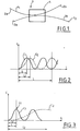
- Figure 1 is a schematic representation of the multiplexer according to the invention.
- FIG. 2 is a representation of the coupling rate proposed according to a technique of the prior art.
- FIG. 3 is a representation of the coupling rate of each of the waves as a function of the interaction length.
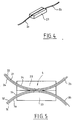
- Figure 4 is the representation of a fiber positioned in its support block.
- FIG. 5 is the representation of a multiplexer according to the invention produced with support blocks.
- the multiplexer 1 of the invention can be a fiber component or an integrated optical component produced for example on a glass or lithium niobate substrate or with silica guides on silicon substrate.
- the device of the invention is a multiplexer 1 comprising two optical fibers 2, 3 referenced 2a and 3a at the input, 2b and 3b at the output.
- a light wave of wavelength ⁇ 1 is coupled into the fiber 2a and an optical wave of wavelength ⁇ 2 is coupled into the fiber 3a.
- an optical wave of wavelength ⁇ 2 is coupled into the fiber 3a.
- the two waves of respective wavelengths ⁇ 1 and ⁇ 2 or at least most of the energy of these two waves are coupled to the fiber 3b.
- the fibers 2 and 3 each have a core respectively referenced 21 and 31 and an optical sheath referenced respectively 22 and 32.
- their mechanical protection is generally ensured by an external sheath which we will not consider here and which is not shown on the figures.
- the fibers 2 and 3 are shaped and maintained so that in the interaction zone 4 their respective hearts 21 and 31 are sufficiently close to each other so that a coupling by evanescent wave of the light waves coupled to each fibers, towards each other occurs.
- this approximation can be obtained by fusion welding and drawing. It can also be obtained by partial removal of the optical sheaths 22 and 32, holding the fibers in position in blocks 23 and 33 then bringing these blocks together. We will limit the description which follows to this latter embodiment.
- the blocks 23 and 33 are made of a material whose geometric properties are stable such as silica.
- each of these blocks a groove 24, 34 is formed, the section of which has a shape and a dimension such that it allows the fibers 21 and 31 to be positioned precisely in this groove.
- the section of this groove can have a shape of - U - or a shape of - V -.
- Each of these grooves has its central axis contained in a plane and a greater depth at the ends of the block than in the central part.
- the fibers 21 and 31 placed in these grooves 24 and 34 are close to each other in the vicinity of the centers of the blocks 21, 23 and 33.
- the depth of the grooves 24, 34 defines the curvature of the fibers in the interaction zone.
- the fibers 2 and 3 from which part of the optical sheath 22, 32 has been removed is flush with the surface of the blocks 23 and 33. This removal is carried out by lateral polishing.
- the contacting of the blocks 23 and 33 generates the contacting of the fibers, by their sheaths and defines an interaction zone.
- Such a device produces the coupling of the input waves by evanescent wave. More precisely, the light energy contained in the light wave, coupled at the input to one of the optical fibers is transferred, more or less completely, to the other fiber.
- the transfer rate shown in Figure 2 is a function of the interaction length of the fibers with respect to each other.
- This interaction length L is a function of the geometric parameters of the system, that is to say the distance h of the fibers, the offset d and the radii of curvature R1 and R2.
- the coupling rate c is defined as being the energy ratio between the outgoing flow by the optical fiber different from the input fiber over the coupled flow in the input fiber.
- This rate c varies sinusoidally as a function of the interaction length L.
- the length of interaction L1 is the smallest for which the coupling rate c is maximum.
- the coupling rate of the wave at wavelength ⁇ 1 is c1 and the coupling rate of the wave at length ⁇ 2 is c2.
- the coupling lengths L1 and L2 are close to each other on the other and it was proposed to carry out a multiplexer by choosing an interaction length L which is an even multiple of L1 and an odd multiple of L2.
- the energy of the light wave at the wavelength ⁇ 1 is maintained in the input fiber, that is to say in the first fiber, while the light energy of the wave at the length of ⁇ 2 wave is transferred from the input fiber (the second fiber) to the other fiber (the first).
- This determination of the interaction length can be carried out with a certain uncertainty and the adjustments which are necessary are therefore relatively simple and a good quality of the multiplexing can reasonably be obtained.
- optimization of the interaction length is achieved by relative displacement of the blocks 23 and 33 by means of mechanical precision movement and by observing the intensity of the outgoing flows by the fibers 2b and 3b.
- part of the optical sheath of the fibers 2 and 3 is removed after positioning the fiber in the block by polishing the assembly.
- the blocks 23 and 33 are preferably fixed relative to each other by gluing.
- an index liquid is interposed between the blocks 23 and 33 so as to improve the coupling.
- the multiplexer of the invention is used to amplify a light signal carried by the first optical wave at the wavelength ⁇ 1.
- the first fiber specially doped with rare earths is single mode at the wavelength ⁇ 1.
- the wave at wavelength ⁇ 2 is called the pump wave. It has a wavelength ⁇ 2 generally significantly less than the wavelength ⁇ 1, preferably ⁇ 1 is greater than or equal to 1.5 ⁇ 2.
- a pump wave with a wavelength equal to 0.532 ⁇ m, 0.820 ⁇ m or 0.980 ⁇ m can be used.
- optical fibers 2 and 3 are birefringent fibers.
Landscapes
- Physics & Mathematics (AREA)
- General Physics & Mathematics (AREA)
- Optics & Photonics (AREA)
- Optical Communication System (AREA)
- Mechanical Coupling Of Light Guides (AREA)
- Optical Integrated Circuits (AREA)
Applications Claiming Priority (2)
| Application Number | Priority Date | Filing Date | Title |
|---|---|---|---|
| FR9013663A FR2668868B1 (fr) | 1990-11-05 | 1990-11-05 | Multiplexeur en longueur d'onde. |
| FR9013663 | 1990-11-05 |
Publications (1)
| Publication Number | Publication Date |
|---|---|
| EP0485276A1 true EP0485276A1 (de) | 1992-05-13 |
Family
ID=9401841
Family Applications (1)
| Application Number | Title | Priority Date | Filing Date |
|---|---|---|---|
| EP91402962A Withdrawn EP0485276A1 (de) | 1990-11-05 | 1991-11-05 | Wellenlängenmultiplexer |
Country Status (4)
| Country | Link |
|---|---|
| EP (1) | EP0485276A1 (de) |
| JP (1) | JPH06201944A (de) |
| CA (1) | CA2054904A1 (de) |
| FR (1) | FR2668868B1 (de) |
Citations (4)
| Publication number | Priority date | Publication date | Assignee | Title |
|---|---|---|---|---|
| EP0103382A2 (de) * | 1982-08-11 | 1984-03-21 | The Board Of Trustees Of The Leland Stanford Junior University | Fiberoptischer Verstärker |
| US4834481A (en) * | 1985-11-12 | 1989-05-30 | Gould Inc. | In-line single-mode fiber optic multiplexer/demultiplexer |
| EP0322744A2 (de) * | 1987-12-25 | 1989-07-05 | Hitachi, Ltd. | Optischer Wellenleiter |
| US4963832A (en) * | 1989-08-08 | 1990-10-16 | At&T Bell Laboratories | Erbium-doped fiber amplifier coupling device |
-
1990
- 1990-11-05 FR FR9013663A patent/FR2668868B1/fr not_active Expired - Fee Related
-
1991
- 1991-11-04 CA CA 2054904 patent/CA2054904A1/en not_active Abandoned
- 1991-11-05 JP JP34935391A patent/JPH06201944A/ja active Pending
- 1991-11-05 EP EP91402962A patent/EP0485276A1/de not_active Withdrawn
Patent Citations (4)
| Publication number | Priority date | Publication date | Assignee | Title |
|---|---|---|---|---|
| EP0103382A2 (de) * | 1982-08-11 | 1984-03-21 | The Board Of Trustees Of The Leland Stanford Junior University | Fiberoptischer Verstärker |
| US4834481A (en) * | 1985-11-12 | 1989-05-30 | Gould Inc. | In-line single-mode fiber optic multiplexer/demultiplexer |
| EP0322744A2 (de) * | 1987-12-25 | 1989-07-05 | Hitachi, Ltd. | Optischer Wellenleiter |
| US4963832A (en) * | 1989-08-08 | 1990-10-16 | At&T Bell Laboratories | Erbium-doped fiber amplifier coupling device |
Non-Patent Citations (1)
| Title |
|---|
| ELECTRONICS LETTERS. vol. 21, no. 10, Mai 1985, STEVENAGE GB pages 415 - 416; J. YOKOHAMA ET AL.: 'Fibre-optic polarising beam splitter employing birefringent-fibre coupler' * |
Also Published As
| Publication number | Publication date |
|---|---|
| FR2668868A1 (fr) | 1992-05-07 |
| JPH06201944A (ja) | 1994-07-22 |
| CA2054904A1 (en) | 1992-05-06 |
| FR2668868B1 (fr) | 1993-06-18 |
Similar Documents
| Publication | Publication Date | Title |
|---|---|---|
| FR2537733A1 (fr) | Dispositif guide d'ondes optique | |
| EP2286289B1 (de) | Vorrichtung zum kuppeln einer glasfaser und einer nanophotonischen komponente | |
| EP0825464B1 (de) | Verfahren zur Herstellung und Montage von einem kollektiven optischen Kopplungselement am Ende eines Bündels von mehreren Monomodenfasern | |
| EP0005093B1 (de) | Optische integrierte Demultiplexieranordnung und Verfahren zu seiner Herstellung | |
| EP0220439A2 (de) | Aufgeweitetes Faserende und hiermit realisierte Koppelanordnungen | |
| FR2595477A1 (fr) | Circuit optique de demultiplexage/multiplexage | |
| FR2558607A1 (fr) | Demultiplexeur optique de longueurs d'ondes | |
| FR2544883A1 (fr) | Multiplexeur/demultiplexeur optique | |
| EP0069054A2 (de) | Vorrichtung zur Verbindung von optischen Fasern und Verfahren zu ihrer Herstellung | |
| EP0346232B1 (de) | Verfahren und System zur Verbindung von Glasfasern ohne Fresnel-Reflexion, veränderlicher optischer Abschwächer und System unter Verwendung desselben zur Messung des Einflusses des Reflexionsgrads auf eine optische Uebertragungsstrecke | |
| Winzer et al. | Single-mode and multimode all-fiber directional couplers for WDM | |
| US20110110629A1 (en) | Planar optical waveguide | |
| EP0665615B1 (de) | Optischer Verstärker aus Fluoridglasfasern und Verfahren zu seiner Herstellung | |
| EP1058138A1 (de) | Multiplexer/Demultiplexer mit drei Wellenleitern | |
| CA2160217C (fr) | Coupleur optique selectif en longueur d'onde | |
| EP0485276A1 (de) | Wellenlängenmultiplexer | |
| JPS61282803A (ja) | 光合波分波装置 | |
| FR2731573A1 (fr) | Multiplexeur-demultiplexeur de longueurs d'onde optique | |
| EP0703475A1 (de) | Wellenlängenselektiver optischer Koppler mit Mehrfachkernlichleitfaser | |
| EP1538469B1 (de) | Lichtempfindlicher optischer Wellenleiter | |
| EP1359442B1 (de) | Apodisierter komplexer Filter | |
| EP1433006B1 (de) | Optische komponente für die spektrale separation von licht verschiedener wellenlängen | |
| EP1151334B1 (de) | Dämpfungsglied für monomodefaser und zugehöriges herstellungsverfahren | |
| Reichelt et al. | Wavelength-division multi demultiplexers for two-channel single-mode transmission systems | |
| US12164149B2 (en) | Multichannel optical tap devices |
Legal Events
| Date | Code | Title | Description |
|---|---|---|---|
| PUAI | Public reference made under article 153(3) epc to a published international application that has entered the european phase |
Free format text: ORIGINAL CODE: 0009012 |
|
| AK | Designated contracting states |
Kind code of ref document: A1 Designated state(s): DE GB IT NL |
|
| 17P | Request for examination filed |
Effective date: 19920810 |
|
| 17Q | First examination report despatched |
Effective date: 19940722 |
|
| STAA | Information on the status of an ep patent application or granted ep patent |
Free format text: STATUS: THE APPLICATION IS DEEMED TO BE WITHDRAWN |
|
| 18D | Application deemed to be withdrawn |
Effective date: 19950202 |