EP0485344B1 - Dispositif d'emmagasinage temporaire pour récipients, en particulier pour bouteilles en PET ou PVC - Google Patents
Dispositif d'emmagasinage temporaire pour récipients, en particulier pour bouteilles en PET ou PVC Download PDFInfo
- Publication number
- EP0485344B1 EP0485344B1 EP91830355A EP91830355A EP0485344B1 EP 0485344 B1 EP0485344 B1 EP 0485344B1 EP 91830355 A EP91830355 A EP 91830355A EP 91830355 A EP91830355 A EP 91830355A EP 0485344 B1 EP0485344 B1 EP 0485344B1
- Authority
- EP
- European Patent Office
- Prior art keywords
- tracks
- track
- duct
- containers
- movement
- Prior art date
- Legal status (The legal status is an assumption and is not a legal conclusion. Google has not performed a legal analysis and makes no representation as to the accuracy of the status listed.)
- Expired - Lifetime
Links
- 238000003860 storage Methods 0.000 title claims description 25
- 230000007246 mechanism Effects 0.000 claims description 10
- 244000027321 Lychnis chalcedonica Species 0.000 claims description 5
- 239000007788 liquid Substances 0.000 claims description 4
- 230000000844 anti-bacterial effect Effects 0.000 claims description 2
- 239000003599 detergent Substances 0.000 claims description 2
- 238000000071 blow moulding Methods 0.000 description 11
- 238000004519 manufacturing process Methods 0.000 description 6
- 238000009434 installation Methods 0.000 description 5
- 238000000034 method Methods 0.000 description 5
- 229920003023 plastic Polymers 0.000 description 5
- 239000004033 plastic Substances 0.000 description 5
- 229920000915 polyvinyl chloride Polymers 0.000 description 4
- 239000004800 polyvinyl chloride Substances 0.000 description 4
- 230000000694 effects Effects 0.000 description 3
- 230000008569 process Effects 0.000 description 3
- 230000008901 benefit Effects 0.000 description 2
- 239000000463 material Substances 0.000 description 2
- 230000002411 adverse Effects 0.000 description 1
- 239000003899 bactericide agent Substances 0.000 description 1
- 230000005540 biological transmission Effects 0.000 description 1
- 230000008859 change Effects 0.000 description 1
- 239000003638 chemical reducing agent Substances 0.000 description 1
- 238000010276 construction Methods 0.000 description 1
- 230000001419 dependent effect Effects 0.000 description 1
- 239000000945 filler Substances 0.000 description 1
- 238000012544 monitoring process Methods 0.000 description 1
- 229920000573 polyethylene Polymers 0.000 description 1
- 230000009467 reduction Effects 0.000 description 1
- 238000005728 strengthening Methods 0.000 description 1
- 230000000007 visual effect Effects 0.000 description 1
- 239000002699 waste material Substances 0.000 description 1
Images




Classifications
-
- B—PERFORMING OPERATIONS; TRANSPORTING
- B65—CONVEYING; PACKING; STORING; HANDLING THIN OR FILAMENTARY MATERIAL
- B65G—TRANSPORT OR STORAGE DEVICES, e.g. CONVEYORS FOR LOADING OR TIPPING, SHOP CONVEYOR SYSTEMS OR PNEUMATIC TUBE CONVEYORS
- B65G47/00—Article or material-handling devices associated with conveyors; Methods employing such devices
- B65G47/34—Devices for discharging articles or materials from conveyor
- B65G47/46—Devices for discharging articles or materials from conveyor and distributing, e.g. automatically, to desired points
- B65G47/51—Devices for discharging articles or materials from conveyor and distributing, e.g. automatically, to desired points according to unprogrammed signals, e.g. influenced by supply situation at destination
- B65G47/5104—Devices for discharging articles or materials from conveyor and distributing, e.g. automatically, to desired points according to unprogrammed signals, e.g. influenced by supply situation at destination for articles
- B65G47/5109—Devices for discharging articles or materials from conveyor and distributing, e.g. automatically, to desired points according to unprogrammed signals, e.g. influenced by supply situation at destination for articles first In - First Out systems: FIFO
- B65G47/5113—Devices for discharging articles or materials from conveyor and distributing, e.g. automatically, to desired points according to unprogrammed signals, e.g. influenced by supply situation at destination for articles first In - First Out systems: FIFO using endless conveyors
-
- B—PERFORMING OPERATIONS; TRANSPORTING
- B29—WORKING OF PLASTICS; WORKING OF SUBSTANCES IN A PLASTIC STATE IN GENERAL
- B29C—SHAPING OR JOINING OF PLASTICS; SHAPING OF MATERIAL IN A PLASTIC STATE, NOT OTHERWISE PROVIDED FOR; AFTER-TREATMENT OF THE SHAPED PRODUCTS, e.g. REPAIRING
- B29C2949/00—Indexing scheme relating to blow-moulding
- B29C2949/07—Preforms or parisons characterised by their configuration
- B29C2949/0715—Preforms or parisons characterised by their configuration the preform having one end closed
-
- B—PERFORMING OPERATIONS; TRANSPORTING
- B29—WORKING OF PLASTICS; WORKING OF SUBSTANCES IN A PLASTIC STATE IN GENERAL
- B29C—SHAPING OR JOINING OF PLASTICS; SHAPING OF MATERIAL IN A PLASTIC STATE, NOT OTHERWISE PROVIDED FOR; AFTER-TREATMENT OF THE SHAPED PRODUCTS, e.g. REPAIRING
- B29C49/00—Blow-moulding, i.e. blowing a preform or parison to a desired shape within a mould; Apparatus therefor
- B29C49/02—Combined blow-moulding and manufacture of the preform or the parison
- B29C49/06—Injection blow-moulding
-
- B—PERFORMING OPERATIONS; TRANSPORTING
- B29—WORKING OF PLASTICS; WORKING OF SUBSTANCES IN A PLASTIC STATE IN GENERAL
- B29C—SHAPING OR JOINING OF PLASTICS; SHAPING OF MATERIAL IN A PLASTIC STATE, NOT OTHERWISE PROVIDED FOR; AFTER-TREATMENT OF THE SHAPED PRODUCTS, e.g. REPAIRING
- B29C49/00—Blow-moulding, i.e. blowing a preform or parison to a desired shape within a mould; Apparatus therefor
- B29C49/42—Component parts, details or accessories; Auxiliary operations
- B29C49/4273—Auxiliary operations after the blow-moulding operation not otherwise provided for
- B29C49/42808—Filling the article
-
- B—PERFORMING OPERATIONS; TRANSPORTING
- B65—CONVEYING; PACKING; STORING; HANDLING THIN OR FILAMENTARY MATERIAL
- B65G—TRANSPORT OR STORAGE DEVICES, e.g. CONVEYORS FOR LOADING OR TIPPING, SHOP CONVEYOR SYSTEMS OR PNEUMATIC TUBE CONVEYORS
- B65G2201/00—Indexing codes relating to handling devices, e.g. conveyors, characterised by the type of product or load being conveyed or handled
- B65G2201/02—Articles
- B65G2201/0235—Containers
- B65G2201/0244—Bottles
-
- B—PERFORMING OPERATIONS; TRANSPORTING
- B65—CONVEYING; PACKING; STORING; HANDLING THIN OR FILAMENTARY MATERIAL
- B65G—TRANSPORT OR STORAGE DEVICES, e.g. CONVEYORS FOR LOADING OR TIPPING, SHOP CONVEYOR SYSTEMS OR PNEUMATIC TUBE CONVEYORS
- B65G2201/00—Indexing codes relating to handling devices, e.g. conveyors, characterised by the type of product or load being conveyed or handled
- B65G2201/02—Articles
- B65G2201/0235—Containers
- B65G2201/0244—Bottles
- B65G2201/0247—Suspended bottles
-
- B—PERFORMING OPERATIONS; TRANSPORTING
- B65—CONVEYING; PACKING; STORING; HANDLING THIN OR FILAMENTARY MATERIAL
- B65G—TRANSPORT OR STORAGE DEVICES, e.g. CONVEYORS FOR LOADING OR TIPPING, SHOP CONVEYOR SYSTEMS OR PNEUMATIC TUBE CONVEYORS
- B65G51/00—Conveying articles through pipes or tubes by fluid flow or pressure; Conveying articles over a flat surface, e.g. the base of a trough, by jets located in the surface
- B65G51/02—Directly conveying the articles, e.g. slips, sheets, stockings, containers or workpieces, by flowing gases
- B65G51/03—Directly conveying the articles, e.g. slips, sheets, stockings, containers or workpieces, by flowing gases over a flat surface or in troughs
- B65G51/035—Directly conveying the articles, e.g. slips, sheets, stockings, containers or workpieces, by flowing gases over a flat surface or in troughs for suspended articles, e.g. bottles
Definitions
- the present invention relates to a device for the temporary storage of containers, and in particular for containers moulded in PET or PVC.
- Containers or bottles fashioned in polyethene and polyvinyl chloride are markedly light and instable when empty, especially bottles with petaloid bases.
- plastic bottles are moulded with a strengthening ring or collar around the neck, in such a way as to facilitate handling in conveying systems of the type where the bottles are suspended freely from the neck and propelled in the required direction by forced air.
- bottles have been created with a cup glued to the base, which can be conveyed on belts, or on pierced chains through which a soft suction is generated; such bottles betray the drawback of a somewhat high cost, however.
- a correctly proportioned in-line storage facility enables the filling machine to continue operation even in the event that the blow-moulding equipment should pause occasionally, and in the event of an interruption at the filling machine, likewise, will enable the blow-moulder to continue operating or at least to complete the production cycle on those bottles already in process.
- an advantageous device will be one that can ensure continuity in production at either machine for at least three minutes.
- the device Given that a bottling line of the type in question will turn out an average 30,000 bottles per hour, the device will need to accommodate at least 1,500 bottles, and with 1.5 litre bottles measuring some 88mm in diameter, this would signify a conventional air conveyor over 130 metres in length.
- a further drawback is that of the need for frequent renewal or replacement of the filters associated with such fan units.
- US-A-4 635 784 discloses a storage device according to the preamble of claim 1.
- EP-A-0 310 102 is known a storage process and device in which, in a pneumatic transport system, there is a plurality of fixed channels in which the containers may be shunted by means of an exchanger switch.
- This device has excessive dimensional proportions and it is rather complex.
- a storage device for cartons comprising web and rollers conveyors on which the cartons are moved.
- the cartons can be loaded into and/or unloaded from the storage device by means of lift fingers which can pick up the cartons from the conveyors or can put down the cartons on the conveyors.
- This device is good for cartons or boxes but is completely unsuitable for handling bottles or containers by way of a their collar.
- the object of the present invention is to overcome the drawbacks mentioned above through the adoption of a device of generous storage capacity, though with notably compact dimensions and running costs much lower than those of air conveyors currently employed for the purpose in question.
- a further object of the invention is to provide a temporary storage device that features considerable flexibility in installation and can be modular in construction.
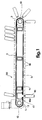
- 1 and 2 denote a pair of tubular shafts, power driven and freely revolving, respectively, each carrying sprockets 12 in mesh with looped chains 3 that are disposed with axes 13 mutually parallel, spaced apart at a distance of one metre or thereabouts and capable of movement in either direction.
- Each chain loop 3 carries a plurality of brackets associated one with every third link 14, or in any event at intervals corresponding to a prescribed whole number of links; each bracket, denoted 5 in its entirety, comprises two arms 6 uppermost of 'Z' profile, and two lower arms 7 to which two relative angle members 8 are rigidly attached and arranged in such a way as to afford support to containers or bottles 10 moulded from a plastics material, each suspended from a collar 9 integral with the neck.
- the angle members 8 are disposed longitudinally in relation to the feed direction of the containers, extending across the full width of the device, and arranged in a succession of convergent pairs each with the innermost edges set apart at a distance marginally greater (by approximately 1mm) than the diameter of the bottle neck 15 in such a way as to afford a track 16 along which the suspended bottles are freely slidable.
- the distance between the axes of two successive tracks 16 is equal to the length of three links 14 of the chain 3.
- the upper arms 6 of the brackets 5 are slidable in guides 44 (e.g. fashioned in plastic) carried by angle elements 45 secured to longitudinal beams 11 that form part of a frame 43 supporting the device.
- guides 44 e.g. fashioned in plastic
- the tracks 16 are thus anchored longitudinally to the chains 3 and supported across their width by the guides 44, which extend along the length of the device.
- the power driven tubular shaft 1 is invested with intermittent movement by means of a conventional maltese cross mechanism (not illustrated), coupled to a geared motor in such a way that the continuous rotation of the motor is converted into indexed rotation at the shaft 1.
- the assembly of chains 3 and tracks 16 can be invested with a substantially uniform accelerating and decelerating movement and brought to a halt accurately following a step equal to three times the pitch of the chain, such that with each step, each successive track 16 occupies the place vacated by the track preceding, considered in the direction of movement.
- 16a denotes the track onto or from which a rank of bottles 10 is loaded or unloaded (the track, also, along which bottles pass freely in transit during normal operation).
- loading, unloading and transit can occur only when one track is positioned coaxially beneath the duct 17 of a pneumatic or air conveyor which forms an integral part of the device according to the invention.
- the power driven shaft 1 and the freely revolving shaft 2, the chains 3 and the sprockets 12, the brackets 5, upper arms 6 and lower arms 7, angle members 8 and guides 44 together constitute means by which to invest the tracks 16 with movement in the manner described above.
- the duct 17 is maintained at pressure marginally greater than atmospheric by a fan unit denoted 18, and affords orifices 4 (see fig 5) from which jets of air are expelled in the direction arrowed 51, in such a way as to impinge on the bottles and bring about their movement along the track 16a.
- the length of the duct 17 is such that it projects from either side of the frame 43, the spaces below the projections being occupied by respective fixed tracks 16b similar in profile to the tracks 16 of the device and connecting the track 16a currently beneath the duct with the machines preceding and following.
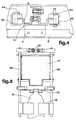
- Such an arrangement facilitates connections to the adjoining air conveyors of the production line, as well as affording space in which to accommodate an arrester device illustrated in figs 6, 7 and 8 and in which to install photocells 19 for monitoring the flow of bottles through the device.
- the butterfly mechanism 20 comprises a baffle 21 operated via a mechanical linkage from a cam 22 rigidly associated with the drive shaft 23 of the maltese cross mechanism, in such a way as to close off the duct 17 prior to the indexing movement of the device and thus ensure that the movement of the bottles is not obstructed by the air jets as the tracks 16 change position.
- the baffle 21 is disposed along the axis of the duct 17 to admit the flow of forced air, and the track 16a beneath the duct faultlessly aligned with the fixed tracks 16b on either side to allow transit of the bottles.
- the mechanical linkage connecting the baffle 21 to the cam 22 comprises a following roller 24, carried by a rocker arm 25 and biased toward the cam 22 by a spring (not shown), a fulcrum pivot 26 carrying the rocker arm 25, and a connecting rod 27 through which the rocker arm 25 is associated with a lever 28 connected to a rotatable shaft 29 supporting the baffle 21.
- a link 30 Also associated with one member of the same rocker arm 25 (as shown in fig 3) is a link 30, connected via transmission levers 31 to a rod 32 positioned in such a manner as to rise vertically whenever a foot 33 attached to its bottom end is struck by the neck of a bottle 10 occupying the area at which the moving and fixed tracks 16a and 16b align with one another.
- This upward movement of the rod 32 causes a plate denoted 34 to be distanced from a corresponding proximity sensor 35, of which the function is to verify the presence or absence of the bottle 10.
- this comprises a pneumatic cylinder 35 of which the rod 38 interacts with two rollers 36 mounted to the ends of two mutually opposed arms 37 urged against the rod 38 by means of respective springs 39.
- the at-rest position of the arms 37 is adjusted by means of setscrews 40.
- Each of the arms 37 affords support by way of a relative shaft 46 to a contoured flap 41 and to a restraint 47, of which the purpose is to block the fixed track 16b and thus prevent the passage of bottles to the track 16a currently in position beneath the duct 17, according to given operating situations that will be described in due course.
- the various components constituting the arrester device i.e. arms 37 and rollers 36, flaps 41 and restraints 47, shafts 46, springs 39, setscrews 40 and the pneumatic cylinder 35, are all mounted to a plate denoted 42.
- An additional arrester device (not illustrated) positioned at the remaining end of the track 16a, similar to that described above or at all events of conventional embodiment, serves in like manner to prevent the bottles from unloading when necessary.
- Figs 9 and 10 illustrate two possible variations in embodiment and installation of the storage device, which differ in layout from the essentially 'flat' design described thus far.
- fig 9 in particular exhibits an 'upright' triangular configuration substantially of isosceles geometry, supported by a frame 43 and with each chain 3 looped around three sprockets 12, whilst that of fig 10 is designed for installation against a wall and exhibits substantially a right angled triangular profile, with each chain 3 again looped around three sprockets 12 and one branch of the chain disposed parallel to the wall.
- a device according to the invention can be embodied to modular design principles and is able to afford high storage capacity; loading, unloading or normal transit of the bottles can be brought about by a single fan unit at the entry to the duct 17, and drive systems are limited to just one geared motor that operates simply to index the tracks carrying the ranks of bottles, thereby achieving a notable saving in energy and in installation and servicing costs, compared to the devices currently in use.
- the device according to the invention might be adapted to operate with any given style of container, preferably of plastics material, such as can be suspended and handled by way of a projection issuing from the neck.
- the bottles pass along beneath the duct 17 of the device as if along any ordinary air conveyor, flowing uniformly or otherwise but without accumulating.
- the flow of bottles must be sufficient to satisfy the demand of the filling machine, and accordingly, a count is made of the bottles running into and out of the device by means of photocells 19a and 19b installed on the fixed tracks 16b respectively preceding and following the track 16a in position beneath the duct 17; thus, a tally can be kept of the number of bottles 10 occupying the track 16a at any given moment, utilizing an electronic counter updated by addition from the first photocell 19a and by subtraction from the second 19b.
- a sensor will be activated to trigger the arrester device located at the exit end of the track 16a.
- the track 16a begins to fill, and will continue accumulating bottles until the electronic counter registers a prescribed number dependent upon the length of the track and the diameter of the bottle in production.
- the counter then emits an electrical control signal to operate the arrester device at the entry end of the channel 17 and the tracks 16 will index one step, corresponding to the length of three links of the chain 3 and to one revolution of the geared motor output shaft.
- the track 16a filled with bottles thus moves away and its place beneath the duct 17 is taken by an empty track, whereupon the procedure thus described is repeated as long as there are empty tracks 16 available.
- bottles will begin to discharge from the device in order to maintain the supply to the filling machine.
- the track 16a empties, and with reduction of the electronic count to zero, the arrester device at the entry to the duct 17 is activated and further ranks of bottles begin to unload, the procedure from this point being substantially the reverse of that described above in respect of a stoppage at the filling machine; unloading continues until such time as the blow-moulding machine resumes normal operation or until the device is completely empty.
- a further photocell 50 is installed preceding the last four or five empty tracks of the device, which can be used to perform two control functions.
- the signal emitted by the photocell can be used to step up the output of the filling machine in relation to that of the blow-moulding machine so as to deplete the contents of the storage facility down to a level determined by a further minimum limit photocell wich serves to restore the normal tempo of the filling machine.
- the signal can be used to prevent the device from filling up completely in such a way that a number of reserve tracks will always remain available to accommodate bottles still forming in the blow-moulding machine.
- a numerical display may also be installed to the end of providing personnel with a continuously updated visual indication of the number of bottles held in temporary storage.
- the maltese cross mechanism might be replaced to equally good effect, for example, with a speed reducer and stepping motor controlled by an encoder, or with a pneumatically controlled two-way ratchet mechanism.
- a temporary storage device thus embodied is easily and automatically cleaned by means of a system of pipes (not illustrated) installed parallel to the tracks between the chains and carrying nozzles from which a liquid containing detergent and bactericide is directed onto the tracks.
- the soiled liquid will be collected in a vessel positioned beneath the device, and disposed of or recycled as appropriate.
Landscapes
- Engineering & Computer Science (AREA)
- Mechanical Engineering (AREA)
- Filling Of Jars Or Cans And Processes For Cleaning And Sealing Jars (AREA)
- Processing And Handling Of Plastics And Other Materials For Molding In General (AREA)
Claims (12)
- Un dispositif d'emmagasinage temporaire par rangées , qui convient en particulier pour des bouteilles en PET ou en PVC qui comprend:- un transporteur équipé d'un conduit (17) le long duquel les récipients (10) passent en transit, et en proximité duquel les récipients sont aussi chargés dans le dispositif ou déchargés de ce dernier;- une pluralité de voies (16) mobiles, parallèles les unes aux autres et équidistantes, au moyen desquelles les récipients peuvent être accumulés et relâchés en rangées correspondantes;- des moyens par lesquels déplacer les voies (16) de telle sorte que les récipients (10) puissent être prélevés ou relâchés en rangées ou transportés librement à travers le dispositif,- chaque voie (16a) étant une portion du transporteur quand la voie (16a) est positionnée au-dessous du conduit (17) et en alignement exact avec ce dernier,
chaque voie (16a) étant un emplacement d'emmagasinage mobile, ou une voie d'emmagasinage (16) pour les récipients (10) quand la voie (16a) est déplacée dans des positions qui ne sont pas en alignement avec le conduit (17),
caractérisé
par le fait que le transporteur est un transporteur pneumatique qui comprend: une partie qui se trouve à l'entrée (16b) et une partie à la sortie, qui sont disposées en position fixe, et une partie intermédiaire (16a) qui constitue chacune desdites voies mobiles, et chaque voie (16a) a une forme telle qu'elle puisse devenir un transporteur pneumatique mobile pour les récipients (10) qui sont suspendus à partir de cette voie et qui sont maniés au moyen d'un collier (9) associé avec le col. - Un dispositif comme celui de la revendication 1, dans lequel les moyens par lesquels les voies (16) sont mises en mouvement comprennent:- un arbre tubulaire (1) qui est propulsé mécaniquement au moyen d'une croix de Malte ou d'un mécanisme similaire et qui porte des dents (12), et un arbre tubulaire qui tourne librement (2) et qui porte d'autres dents correspondantes;- des chaînes (3) qui sont enroulées autour des arbres, en prise avec les dents (12) relatives et qui peuvent se déplacer dans les deux directions, dont les axes (13) de mouvement sont disposés parallèlement les uns aux autres;- une pluralité de supports (5) qui sont portés à intervalles réguliers par les chaînes (3) et qui comprennent des bras supérieurs (6) et des bras inférieurs (7);- une pluralité d'éléments angulaires et longitudinaux (8) fixés en paires convergentes aux bras inférieurs (7) des supports (5) de telle sorte qu'ils offrent des voies (16) d'où l'on peut suspendre un récipient (10) par le collier (9), qui sont ancrés à chaque chaîne (3) à certains points le long de leur longueur et qui sont supportés transversalement par des guides (44) qui reçoivent les bras supérieurs (6) des supports d'une façon telle qu'ils puissent glisser.
- Un dispositif comme celui de la revendication 1, dans lequel les voies (16) sont disposées parallèlement les unes aux autres à une distance égale l'une de l'autre, et qui sont capables de mouvement de mise en place et parallèles à leurs propres axes dans les deux directions, suivant la direction du mouvement des chaînes (3), par des pas dont la longueur est égale à la distance entre les centres de deux voies successives.
- Un dispositif comme celui de la revendication 1, qui comprend une pluralité de tuyaux qui s'étendent parallèlement aux voies (16) dans l'espace qui est entouré par les chaînes (3) et qui sont garnis d'ajutages d'où un liquide détergent et bactéricide est dirigé vers les voies, et un récipient positionné au-dessous du dispositif dans lequel est recueilli le liquide.
- Un dispositif comme celui de la revendication 1, qui comprend un élément de ventilation (18) par lequel l'air est contraint à travers le conduit (17), et un mécanisme de soupape à papillon (20) par lequel le flux d'air dans le conduit peut être bloqué avec l'élément de ventilation en fonction.
- Un dispositif comme celui de la revendication 5, dans lequel le mécanisme de soupape à papillon comprend un déflecteur (21) actionné à travers des liaisons mécaniques par le mouvement d'une came (22) rigidement associée avec l'arbre (23) d'un mécanisme à croix de Malte, et capable de se mettre en une position fermée, ce qui provoque le blocage du conduit (17) avant un mouvement de mise en place des voies (16) de façon à assurer que le mouvement des bouteilles (10) ne soit pas empêché par un flux d'air provenant du conduit quand les voies sont mises en place, et de se mettre en une position ouverte assumée avec les voies (16) à l'arrêt et une voie (16a) alignée axialement au-dessous du conduit (17), dans laquellle le déflecteur (21) est disposé le long de l'axe du conduit (17) et le flux d'air est laissé entrer.
- Un dispositif comme celui de la revendication 1, dans lequel le nombre de récipients (10) qui entrent et qui quittent la voie (16a) positionnée au-dessous du conduit et en alignement avec ce dernier est contrôlé au moyen de deux photocellules (19a, 19b), l'une précédant la voie (16a) et l'autre la suivant, de telle sorte que le nombre de récipients qui occupent la voie à n'importe quel moment puisse être indiqué par un compteur électronique connecté aux photocellules.
- Un dispositif comme celui de la revendication 1, qui comprend des moyens logés à l'extrémité qui se trouve à l'entrée du conduit (17) par lesquels arrêter les récipients, consistant en des volets courbés (41) et en des encastrements (47) poussés à fonctionner par la rotation d'arbres (46) associés avec des bras (37) qui sont embrayés par la tige (38) d'un cylindre pneumatique (35).
- Un dispositif comme celui de la revendication 1, dans lequel le transporteur, les voies qui offrent un emplacement mobile pour l'emmagasinage et les moyens par lesquels les voies sont mises en mouvement sont portés par une structure (43) et sont disposés en une configuration triangulaire "verticale".
- Un dispositif comme ceux des revendications 2 et 9, dans lequel chaque chaîne (3) est enroulée autour de trois dents (12).
- Un dispositif comme celui de la revendication 1, qui comprend un détecteur en proximité (35) servant à vérifier la présence ou l'absence d'un récipient (10) à la jonction entre la voie (16a) positionnée au-dessous du conduit (17) et en alignement avec ce dernier, et une voie fixe (16b) placée avant le conduit, actionné par le mouvement d'une plaque (34) rigidement associée avec une tige (32) dont l'extrémité inférieure porte un pied (33) positionné pour heurter contre l'extrémité supérieure du récipient.
- Un dispositif comme celui de la revendication 1, dans lequel le dispositif d'emmagasinage est réalisé en une configuration verticale supportée par une structure (43).
Applications Claiming Priority (2)
| Application Number | Priority Date | Filing Date | Title |
|---|---|---|---|
| IT42538A IT1242406B (it) | 1990-11-08 | 1990-11-08 | Dispositivo accumulatore di contenitori, particolarmente adatto per contenitori in pet o pvc. |
| IT4253890 | 1990-11-08 |
Publications (3)
| Publication Number | Publication Date |
|---|---|
| EP0485344A2 EP0485344A2 (fr) | 1992-05-13 |
| EP0485344A3 EP0485344A3 (en) | 1993-04-28 |
| EP0485344B1 true EP0485344B1 (fr) | 1995-11-22 |
Family
ID=11254369
Family Applications (1)
| Application Number | Title | Priority Date | Filing Date |
|---|---|---|---|
| EP91830355A Expired - Lifetime EP0485344B1 (fr) | 1990-11-08 | 1991-08-27 | Dispositif d'emmagasinage temporaire pour récipients, en particulier pour bouteilles en PET ou PVC |
Country Status (3)
| Country | Link |
|---|---|
| EP (1) | EP0485344B1 (fr) |
| DE (1) | DE69114816T2 (fr) |
| IT (1) | IT1242406B (fr) |
Cited By (1)
| Publication number | Priority date | Publication date | Assignee | Title |
|---|---|---|---|---|
| WO2024171102A1 (fr) * | 2023-02-17 | 2024-08-22 | Sacmi Beverage S.p.A. | Dispositif pour le stockage temporaire de contenants |
Families Citing this family (8)
| Publication number | Priority date | Publication date | Assignee | Title |
|---|---|---|---|---|
| IT1253753B (it) * | 1991-10-16 | 1995-08-23 | Program S R L | Magazzeno di recupero,a tamburo,per impianti di produzione e di riempimento per bottiglie in materiale plastico, e simili |
| FR2689110B1 (fr) * | 1992-03-24 | 1998-04-17 | Sidel Sa | Machine de stockage de recipients entre une machine amont delivrant des recipients et une machine aval utilisatrice. |
| FR2755946B1 (fr) | 1996-11-18 | 1999-02-05 | Neu Mec | Machine de traitement en ligne de recipients et ligne de transfert pneumatique de recipients equipee de cette machine |
| DE19846411A1 (de) * | 1998-10-08 | 2000-04-13 | Zahoransky Anton Gmbh & Co | Bürstenherstellungsmaschine |
| DE29915299U1 (de) * | 1999-09-01 | 2000-02-17 | GEA Finnah GmbH, 48683 Ahaus | Vorrichtung zum Vereinzeln und Gruppieren von Flaschen |
| FR2802904B1 (fr) | 1999-12-22 | 2002-05-03 | Netra Systems | Procede de formation d'un train d'articles suspendus transportes sous l'action de jets d'air et troncon de convoyage pour la mise en oeuvre de ce procede |
| CN102633087B (zh) * | 2012-04-17 | 2013-11-20 | 俞晟 | 一种带链段传送槽的输送装置 |
| CN114228107A (zh) * | 2021-12-09 | 2022-03-25 | 江苏辰基包装有限公司 | 一种pet瓶体、生产线及其生产工艺 |
Family Cites Families (4)
| Publication number | Priority date | Publication date | Assignee | Title |
|---|---|---|---|---|
| US4499987A (en) * | 1982-08-30 | 1985-02-19 | Long Charles P | Accumulator for a carton filling and packing production line |
| US4635784A (en) * | 1984-10-03 | 1987-01-13 | Bourgeois Ronald D | Accumulating magazine |
| FR2621302B1 (fr) * | 1987-10-02 | 1992-07-31 | Neu Ets | Procede et dispositif d'accumulation d'objets dans une installation de transport pneumatique |
| US4938636A (en) * | 1988-11-14 | 1990-07-03 | Aidlin Automation Corp. | Method and apparatus for feeding container bodies |
-
1990
- 1990-11-08 IT IT42538A patent/IT1242406B/it active IP Right Grant
-
1991
- 1991-08-27 EP EP91830355A patent/EP0485344B1/fr not_active Expired - Lifetime
- 1991-08-27 DE DE69114816T patent/DE69114816T2/de not_active Expired - Fee Related
Cited By (1)
| Publication number | Priority date | Publication date | Assignee | Title |
|---|---|---|---|---|
| WO2024171102A1 (fr) * | 2023-02-17 | 2024-08-22 | Sacmi Beverage S.p.A. | Dispositif pour le stockage temporaire de contenants |
Also Published As
| Publication number | Publication date |
|---|---|
| IT9042538A1 (it) | 1992-05-08 |
| DE69114816D1 (de) | 1996-01-04 |
| IT9042538A0 (it) | 1990-11-08 |
| EP0485344A2 (fr) | 1992-05-13 |
| DE69114816T2 (de) | 1996-05-15 |
| EP0485344A3 (en) | 1993-04-28 |
| IT1242406B (it) | 1994-03-04 |
Similar Documents
| Publication | Publication Date | Title |
|---|---|---|
| JP3735036B2 (ja) | 物品の流れを制御する装置 | |
| KR920006443B1 (ko) | 공력수송시스템에서 부정수의 물체를 저류하는 방법 및 장치 | |
| CN114538361B (zh) | 用于液体产品的灌装系统和将液体产品灌装到瓶中的方法 | |
| US20240199401A1 (en) | Container treatment system and container treatment method for treating containers | |
| EP0083147B1 (fr) | Système de triage et de manutention de matériaux | |
| EP0485344A2 (fr) | Dispositif d'emmagasinage temporaire pour récipients, en particulier pour bouteilles en PET ou PVC | |
| US5255773A (en) | Accumulator for conveyor system | |
| WO2010022361A2 (fr) | Décélérateur de transport de conteneurs | |
| US4776468A (en) | Bobbin conveying system | |
| US20110056798A1 (en) | Multiplex grouping device | |
| US8028820B2 (en) | Device for storing objects | |
| US5304027A (en) | Buffer storage machine for container conveyor line | |
| US2804961A (en) | Conveyor apparatus for articleprocessing units | |
| US7353643B2 (en) | System for feeding caps with rotating-drum accumulation device | |
| US7017730B2 (en) | Bi-directional mail tray pusher | |
| US20020134056A1 (en) | Packaging apparatus and method | |
| US4574939A (en) | Automatic bottle handling apparatus | |
| EP0427683A1 (fr) | Dispositif pour l'accumulation ordonnée de bouteilles en plastic | |
| US3869843A (en) | Lightweight plastic container case-packing method and apparatus | |
| GB2219783A (en) | A container supply system | |
| US5937994A (en) | Container conveying installation for preparing sets of objects | |
| US5489016A (en) | Pusher bar apparatus to remove containers from a splice plate between conveyors | |
| US6543600B2 (en) | Early detection photo controls | |
| CN217512326U (zh) | 分拣装置和分拣系统 | |
| FR2669311B1 (fr) | Dispositif d'accumulation dynamique de recipients dans une chaine de transfert par jets d'air. |
Legal Events
| Date | Code | Title | Description |
|---|---|---|---|
| PUAI | Public reference made under article 153(3) epc to a published international application that has entered the european phase |
Free format text: ORIGINAL CODE: 0009012 |
|
| AK | Designated contracting states |
Kind code of ref document: A2 Designated state(s): DE FR GB |
|
| PUAL | Search report despatched |
Free format text: ORIGINAL CODE: 0009013 |
|
| AK | Designated contracting states |
Kind code of ref document: A3 Designated state(s): DE FR GB |
|
| 17P | Request for examination filed |
Effective date: 19931014 |
|
| 17Q | First examination report despatched |
Effective date: 19940603 |
|
| GRAA | (expected) grant |
Free format text: ORIGINAL CODE: 0009210 |
|
| AK | Designated contracting states |
Kind code of ref document: B1 Designated state(s): DE FR GB |
|
| REF | Corresponds to: |
Ref document number: 69114816 Country of ref document: DE Date of ref document: 19960104 |
|
| ET | Fr: translation filed | ||
| PLBE | No opposition filed within time limit |
Free format text: ORIGINAL CODE: 0009261 |
|
| STAA | Information on the status of an ep patent application or granted ep patent |
Free format text: STATUS: NO OPPOSITION FILED WITHIN TIME LIMIT |
|
| 26N | No opposition filed | ||
| REG | Reference to a national code |
Ref country code: GB Ref legal event code: IF02 |
|
| PGFP | Annual fee paid to national office [announced via postgrant information from national office to epo] |
Ref country code: DE Payment date: 20070823 Year of fee payment: 17 |
|
| PGFP | Annual fee paid to national office [announced via postgrant information from national office to epo] |
Ref country code: GB Payment date: 20070822 Year of fee payment: 17 |
|
| PGFP | Annual fee paid to national office [announced via postgrant information from national office to epo] |
Ref country code: FR Payment date: 20070808 Year of fee payment: 17 |
|
| GBPC | Gb: european patent ceased through non-payment of renewal fee |
Effective date: 20080827 |
|
| REG | Reference to a national code |
Ref country code: FR Ref legal event code: ST Effective date: 20090430 |
|
| PG25 | Lapsed in a contracting state [announced via postgrant information from national office to epo] |
Ref country code: FR Free format text: LAPSE BECAUSE OF NON-PAYMENT OF DUE FEES Effective date: 20080901 Ref country code: DE Free format text: LAPSE BECAUSE OF NON-PAYMENT OF DUE FEES Effective date: 20090303 |
|
| PG25 | Lapsed in a contracting state [announced via postgrant information from national office to epo] |
Ref country code: GB Free format text: LAPSE BECAUSE OF NON-PAYMENT OF DUE FEES Effective date: 20080827 |