EP0485433B1 - Systeme de positionnement de conteneur - Google Patents
Systeme de positionnement de conteneur Download PDFInfo
- Publication number
- EP0485433B1 EP0485433B1 EP90911521A EP90911521A EP0485433B1 EP 0485433 B1 EP0485433 B1 EP 0485433B1 EP 90911521 A EP90911521 A EP 90911521A EP 90911521 A EP90911521 A EP 90911521A EP 0485433 B1 EP0485433 B1 EP 0485433B1
- Authority
- EP
- European Patent Office
- Prior art keywords
- container
- neck portion
- register
- annular
- alignment relative
- Prior art date
- Legal status (The legal status is an assumption and is not a legal conclusion. Google has not performed a legal analysis and makes no representation as to the accuracy of the status listed.)
- Expired - Lifetime
Links
- 238000000034 method Methods 0.000 claims description 9
- 238000002372 labelling Methods 0.000 claims 2
- 238000004519 manufacturing process Methods 0.000 abstract description 4
- 238000009826 distribution Methods 0.000 abstract description 3
- 239000000047 product Substances 0.000 description 8
- 239000007788 liquid Substances 0.000 description 5
- 238000013459 approach Methods 0.000 description 4
- 239000000945 filler Substances 0.000 description 3
- 239000004033 plastic Substances 0.000 description 3
- 229920003023 plastic Polymers 0.000 description 3
- 238000000071 blow moulding Methods 0.000 description 2
- 238000005516 engineering process Methods 0.000 description 2
- 230000036961 partial effect Effects 0.000 description 2
- 238000003860 storage Methods 0.000 description 2
- 108010053481 Antifreeze Proteins Proteins 0.000 description 1
- 239000002390 adhesive tape Substances 0.000 description 1
- 230000002411 adverse Effects 0.000 description 1
- 230000002528 anti-freeze Effects 0.000 description 1
- 230000002860 competitive effect Effects 0.000 description 1
- 238000010101 extrusion blow moulding Methods 0.000 description 1
- 238000005429 filling process Methods 0.000 description 1
- 230000009969 flowable effect Effects 0.000 description 1
- 238000011065 in-situ storage Methods 0.000 description 1
- 238000010102 injection blow moulding Methods 0.000 description 1
- 239000012263 liquid product Substances 0.000 description 1
- 239000000463 material Substances 0.000 description 1
- 239000008267 milk Substances 0.000 description 1
- 210000004080 milk Anatomy 0.000 description 1
- 235000013336 milk Nutrition 0.000 description 1
- 238000004806 packaging method and process Methods 0.000 description 1
- 230000002093 peripheral effect Effects 0.000 description 1
- 238000003825 pressing Methods 0.000 description 1
- 230000000630 rising effect Effects 0.000 description 1
- 239000000243 solution Substances 0.000 description 1
Images

Classifications
-
- G—PHYSICS
- G07—CHECKING-DEVICES
- G07F—COIN-FREED OR LIKE APPARATUS
- G07F13/00—Coin-freed apparatus for controlling dispensing or fluids, semiliquids or granular material from reservoirs
- G07F13/10—Coin-freed apparatus for controlling dispensing or fluids, semiliquids or granular material from reservoirs with associated dispensing of containers, e.g. cups or other articles
-
- B—PERFORMING OPERATIONS; TRANSPORTING
- B65—CONVEYING; PACKING; STORING; HANDLING THIN OR FILAMENTARY MATERIAL
- B65D—CONTAINERS FOR STORAGE OR TRANSPORT OF ARTICLES OR MATERIALS, e.g. BAGS, BARRELS, BOTTLES, BOXES, CANS, CARTONS, CRATES, DRUMS, JARS, TANKS, HOPPERS, FORWARDING CONTAINERS; ACCESSORIES, CLOSURES, OR FITTINGS THEREFOR; PACKAGING ELEMENTS; PACKAGES
- B65D1/00—Rigid or semi-rigid containers having bodies formed in one piece, e.g. by casting metallic material, by moulding plastics, by blowing vitreous material, by throwing ceramic material, by moulding pulped fibrous material or by deep-drawing operations performed on sheet material
- B65D1/02—Bottles or similar containers with necks or like restricted apertures, designed for pouring contents
- B65D1/0223—Bottles or similar containers with necks or like restricted apertures, designed for pouring contents characterised by shape
- B65D1/023—Neck construction
-
- B—PERFORMING OPERATIONS; TRANSPORTING
- B65—CONVEYING; PACKING; STORING; HANDLING THIN OR FILAMENTARY MATERIAL
- B65D—CONTAINERS FOR STORAGE OR TRANSPORT OF ARTICLES OR MATERIALS, e.g. BAGS, BARRELS, BOTTLES, BOXES, CANS, CARTONS, CRATES, DRUMS, JARS, TANKS, HOPPERS, FORWARDING CONTAINERS; ACCESSORIES, CLOSURES, OR FITTINGS THEREFOR; PACKAGING ELEMENTS; PACKAGES
- B65D51/00—Closures not otherwise provided for
- B65D51/24—Closures not otherwise provided for combined or co-operating with auxiliary devices for non-closing purposes
-
- Y—GENERAL TAGGING OF NEW TECHNOLOGICAL DEVELOPMENTS; GENERAL TAGGING OF CROSS-SECTIONAL TECHNOLOGIES SPANNING OVER SEVERAL SECTIONS OF THE IPC; TECHNICAL SUBJECTS COVERED BY FORMER USPC CROSS-REFERENCE ART COLLECTIONS [XRACs] AND DIGESTS
- Y10—TECHNICAL SUBJECTS COVERED BY FORMER USPC
- Y10S—TECHNICAL SUBJECTS COVERED BY FORMER USPC CROSS-REFERENCE ART COLLECTIONS [XRACs] AND DIGESTS
- Y10S215/00—Bottles and jars
- Y10S215/90—Collapsible wall structure
Definitions
- the present invention concerns improvements relating to, inter alia, liquid dispensing systems, and especially to systems for dispensing liquids from bulk liquid supplies on a demand basis an to a dispensing apparatus.
- liquid products such as for example automobile windshield washer anti-freeze, oil and the like, or comestibles such as milk
- a retail outlet storage, logistics and retail space problems tend to increase a retailers operating costs.
- An alternative approach to merchandising such goods is to provide in-store dispensing of such liquids from a bulk supply thereof. Manual dispensing must be carried out either by the purchaser or by retail store personnel. Customer service conscious retailers do not tend to view dispensing by the purchaser as a particularly attractive form of retailing. Health, safety, portion control and other considerations may also adversely relate to this approach to dispensing products. Retail store personnel are not generally cost effective when employed in the role of dispenser operators.
- Vending machine technologies for automating the dispensing of products provides a partial solution to some of the problems facing retailers of the products in question, but in general are not readily adaptable to a wide range of products and do not provide the benefits of on site dispensing of bulk products.
- US patent 4,120,134 discloses an apparatus for filling flexible containers which are fed to the apparatus as a continuous web arranged in such a way as to provide for predetermined alignment of succeeding containers at a filling station.
- the respective neck portions of the containers support annular rings which are adapted to be received between the mutually opposed edges of two inwardly extending flanges of a gripping device having an opening with a complimentary profile.
- the gripping device then receives the annular ring supporting portion of the containers neck, and mechanically orients the opening in the neck with a filler spout on the apparatus.
- US patent 3,242,951 discloses a web-feeding filler apparatus filler head, adapted to receive a specially shaped cap secured to the neck of the container to be filled. Peripheral edges of the cap a cut away, so as to engage in a plowing relationship with shaped portions of the filling head. This arrangement is intended to orient the container in a predetermined relation to the filling head during the filling process, but requires that a particular cap shape be employed, which is both relatively costly and limiting from a marketing point of view.
- the present invention relates to a container having at least one flat arranged along a neck portion thereof and first and second annular tabs arranged in encircling relation around said neck portion in opposed encircling relation to one another across said at least one flat.
- the tabs and at least one flat are adapted to be received in register with corresponding portions of mechanical means for selectively positioning the container in predetermined radial and axial alignment relative thereto during mechanical handling operations thereof.
- Such operations include any one or more of the operations selected from the group consisting of production; distribution; or, filling, of the container.
- the container will be positioned in a specific radial and axial orientation relative to the handling means. This facilitates handling of asymmetrical containers such as, for example, containers where the neck is offset to one side thereof or containers having grasping means which must be specifically positioned relative to a dispensing spout.
- the container comprises at least two flats arranged on diametrically opposed side of the neck portions.
- the neck portion includes at least two axially spaced apart annular tabs arranged opposite one another across the abovementioned flats.
- the first annular tab is arranged along the neck at an axial location immediately below a proximal edge of a closure adapted to be secured to the neck, and this tab is at least radially coextensive with the closure when the closure is so secured.
- the second annular tab preferably comprises a raised portion of a shoulder of the container.
- the present invention includes a method of handling a container substantially as described hereinbefore, comprising the steps of engaging the flats in secured register with the corresponding means and selectively positioning the container in a predetermined radial and axial alignment relative thereto.
- blow molding takes one of a least two basic approaches: injection blow molding; and, extrusion blow molding. The latter is the most widely commercially used method, and includes both rising mold and parison transfer methods. Parison programming is used in known manner to control wall thickness of various portions of the containers walls and neck, etc.
- the molded container is positioned in predetermined radial alignment relative to the bottle transfer means, it is, if required, transferred to a flash removal station in predetermined radial alignment at the station to align flash lines on the bottle with flash removing means.
- the flats are preferably located in radially spaced apart relation from flash lines extending along the neck portion, so as to provide clear access to the flash lines for the flash removing means.
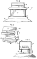
- a container of the present invention comprising a bottle 1, having a collapsible body manufactured from thin plastics material and being collapsible for storage or transport purposes, along hinge lines 2 integrally formed along side walls thereof.
- Bottle 1 also includes grasping means in the form of an integrally formed handle 3.
- Neck portion 4 of the bottle includes indexing means comprising at least one flat 5 arranged along neck portion 4.
- bottle 1 actually includes two such flats which are arranged on diametrically opposed sides of said neck portions and are adapted to be received in register with corresponding portions of means for selectively positioning said container in predetermined radial alignment relative thereto during handling operations thereof.
- Neck portion 4 includes further indexing means comprising two annular tabs, 6 and 7, adapted to be secured in register with corresponding portions of means for selectively positioning the container in predetermined axial alignment thereto.
- Annular tabs 6 and 7 are axially spaced apart from one another across said flats.
- Tab 7 comprises a raised portion of shoulder 8 of bottle 1.
- Tab 6 is arranged along neck portion 4 at an axial location immediately below a point where a lower proximal edge of a closure, (not shown in this figure) is adapted to be positioned with the closure secured to the neck portion 4 in snap-on interfitting relation on annular rib 9.
- Tab 6 is sized to be at least generally radially coextensive with the closure when the closure is so secured.
- flat 5 and the corresponding mutually opposed flat not only provide radial indexing surfaces, but also increase the available amount of surface along mutually opposed surfaces, (eg adjacent flat 5), of annuli 6 and 7 that can be engaged by means for axially securing the bottle.
- FIG. 1 Figure 2 of the drawings depicts the neck portion 4 in greater detail.
- FIG. 3 of the drawings there is shown a portion of an elongated magazine clip 10, adapted to receive a plurality of containers, not shown, for collective distribution and handling thereof, in supported, interfitting, releasably slidable relation with respective waisted portions thereof.
- Clip 10 is operable to direct delivery of succeeding ones of said containers longitudinally along said magazine to an at least one discharge opening therefrom, in this case an open end indicated by reference numeral 11.
- the opening is securable with adhesive tape to prevent bottles from leaving the clip prematurely.
- Clip 10 includes two walls, 12 and 13, each including respective dependant transverse faces, of which only one, 14,is visible in this perspective. These transverse faces are arranged in mutually opposed relation across an elongated opening therebetween, along which opening said waisted portions of said containers are adapted to be releasably slidably arranged between said transverse faces.
- Clip 10 defines a partially enclosed interior between a back wall 15 with two mutually opposed side walls 16 and 17 depending from opposite edges of the back wall 15 and supporting respective partial front walls 12 and 13 in spaced apart relation from the back wall.
- Clip 10 is particularly well adapted to engage waisted neck portions of such containers, and in particular the indexing means of the bottle shown in figures 1 and 2 of the drawings appended hereto.
- Indexing flats 5 thereon are adapted to be positionable in register with said transverse faces (eg 14) to orient the bottle in predetermined relation to said magazine.
- Front walls 12 and 13 are adapted to engage annular tabs 6 and 7 in abutting relation therewith along portions of the walls (including respective recursive portions 18 and 19) in order to secure against withdrawal of said bottle from said clip through said elongated opening between said transverse faces.
- FIG 4 of the drawings shows the neck portion of the bottle of figure 1 located in situ within the interior of clip 10.
- Transverse faces each include a pair of raised ribs 20, extending longitudinally along the faces, which ribs are adapted to abut against said waisted portions in contacting relation therewith, to thereby reduce the amount of mutually contacting frictional surface area between the transverse face of said clip and said container. This arrangement facilitates bottle movement along the length of the clip 10.
Landscapes
- Engineering & Computer Science (AREA)
- Mechanical Engineering (AREA)
- Ceramic Engineering (AREA)
- Physics & Mathematics (AREA)
- General Physics & Mathematics (AREA)
- Supplying Of Containers To The Packaging Station (AREA)
- Auxiliary Devices For And Details Of Packaging Control (AREA)
- Details Of Rigid Or Semi-Rigid Containers (AREA)
- Containers Having Bodies Formed In One Piece (AREA)
- Feeding Of Articles To Conveyors (AREA)
- Filling Of Jars Or Cans And Processes For Cleaning And Sealing Jars (AREA)
Claims (9)
- Conteneur comportant des moyens de positionnement comprenant au moins un plat (5) disposé le long d'une partie de col (4) du conteneur et une première languette annulaire disposée de façon à entourer ladite partie de col, ledit plat au nombre d' un au moins et ladite première languette annulaire (6) étant tous les deux adaptés pour être reçus de façon à être repérés par rapport à des parties correspondantes de moyens mécaniques pour positionner sélectivement ledit conteneur dans un alignement radial prédéterminé par rapport à eux au cours de ses opérations de traitement métalliques, caractérisé par la partie de col comportant une seconde languette annulaire (7) située sur la partie de col qu'elle entoure, opposée à ladite première languette annulaire (6) par rapport audit plat au nombre de un au moins, ladite seconde languette annulaire étant adaptée pour être reçue de façon à être repérée par rapport aux parties respectives correspondantes desdits moyens mécaniques pour positionner simultanément ledit conteneur dans un alignement axial prédéterminé par rapport auxdits moyens mécaniques.
- Conteneur selon la revendication 1 , dans lequel lesdits moyens de positionnement sont constitués d'au moins deux plats disposés sur des côtés diamétralement opposés de ladite partie de col.
- Conteneur selon la revendication 2, dans lequel une desdites première et seconde languettes annulaires (6,7) comprend une partie relevée d'un épaulement dudit conteneur.
- Conteneur selon la revendication 3, dans lequel l'autre desdites première et seconde languettes annulaires est disposée le long dudit col au niveau d'une position axiale située immédiatement au-dessous d'un bord proximal d'une fermeture adaptée pour être fixée audit col et ladite autre languette est au moins, de façon générale, radialement en prolongement de ladite fermeture lorsque ladite fermeture est ainsi fixée.
- Procédé de manipulation d'un conteneur construit selon l'une quelconque des revendications 1, 2, 3 ou 4, caractérisé par les étapes consistant à engager ledit plat au nombre de un au moins et lesdites première et seconde languettes annulaires dans un repérage assuré avec lesdites parties correspondantes respectives desdits moyens mécaniques et à positionner de façon sélective ledit conteneur dans un alignement radial et axial prédéterminé par rapport à ces moyens mécaniques.
- Procédé selon la revendication 5 , dans lequel une préforme est moulée par soufflage pour former ledit conteneur,lequel est ensuite enlevé du moule de soufflage en engageant lesdits plats dans un repérage assuré avec les moyens de transfert des bouteilles moulées pour positionner de façon sélective ledit conteneur dans un alignement radial prédéterminé par rapport à ces moyens de transfert.
- Procédé selon la revendication 6, dans lequel ledit conteneur est positionné dans un alignement radial prédéterminé par rapport auxdits moyens de transfert des bouteilles et est transféré vers un poste d'élimination des bavures dans un alignement radial prédéterminé au niveau dudit poste pour aligner les lignes de bavures sur ladite bouteille avec les moyens d'élimination des bavures.
- Procédé selon la revendication 7, dans lequel les plats sont situés radialement à l'écart des lignes de bavure s'étendant le long de ladite partie de col.
- Procédé selon la revendication 8, dans lequel lesdits plats sont engagés dans un repérage assuré avec des moyens d'étiquetage et sélectivement positionnés dans un alignement radial prédéterminé par rapport à ces moyens pour placer ainsi les surfaces prédéterminées dudit conteneur dans un repérage prédéterminé avec des moyens pour appliquer sur ces surfaces des timbres imprimés d'étiquetage.
Applications Claiming Priority (3)
| Application Number | Priority Date | Filing Date | Title |
|---|---|---|---|
| CA608021 | 1989-08-10 | ||
| CA000608021A CA1334087C (fr) | 1989-08-10 | 1989-08-10 | Systeme de positionnement de contenants |
| PCT/CA1990/000256 WO1991001921A1 (fr) | 1989-08-10 | 1990-08-10 | Systeme de positionnement de conteneur |
Publications (2)
| Publication Number | Publication Date |
|---|---|
| EP0485433A1 EP0485433A1 (fr) | 1992-05-20 |
| EP0485433B1 true EP0485433B1 (fr) | 1994-07-13 |
Family
ID=4140441
Family Applications (1)
| Application Number | Title | Priority Date | Filing Date |
|---|---|---|---|
| EP90911521A Expired - Lifetime EP0485433B1 (fr) | 1989-08-10 | 1990-08-10 | Systeme de positionnement de conteneur |
Country Status (10)
| Country | Link |
|---|---|
| US (1) | US5269427A (fr) |
| EP (1) | EP0485433B1 (fr) |
| AT (1) | ATE108390T1 (fr) |
| AU (1) | AU639939B2 (fr) |
| CA (1) | CA1334087C (fr) |
| DE (1) | DE69010688T2 (fr) |
| DK (1) | DK0485433T3 (fr) |
| ES (1) | ES2056472T3 (fr) |
| HK (1) | HK10996A (fr) |
| WO (1) | WO1991001921A1 (fr) |
Families Citing this family (6)
| Publication number | Priority date | Publication date | Assignee | Title |
|---|---|---|---|---|
| DE9404942U1 (de) * | 1994-03-23 | 1994-06-01 | Loges, Michael, 49497 Mettingen | Tragvorrichtung für Behältnisse |
| GB9524456D0 (en) * | 1995-11-30 | 1996-01-31 | Britton Charles J | Injection stretch blowform moulding |
| CN1113782C (zh) * | 1998-03-20 | 2003-07-09 | 株式会社吉野工业所 | 带手柄的塑料瓶 |
| WO2000021837A1 (fr) | 1998-10-13 | 2000-04-20 | In-Flo Liquid Dispensing Corporation | Procede et appareil de capsulage, d'evacuation et de pliage de recipients plastiques compactables |
| KR100548193B1 (ko) * | 2004-01-02 | 2006-02-01 | 세진테크 주식회사 | 스파우트를 갖춘 파우치용 정렬장치 |
| DE102013109377A1 (de) * | 2013-08-29 | 2015-03-05 | Krones Ag | Verfahren und Vorrichtung zum Befüllen von Großbehältnissen |
Family Cites Families (14)
| Publication number | Priority date | Publication date | Assignee | Title |
|---|---|---|---|---|
| US1833971A (en) * | 1930-04-18 | 1931-12-01 | Carr Lowrey Glass Company | Sprinkler bottle |
| DE620972C (de) * | 1932-11-01 | 1935-11-08 | Jagenberg Werke Ag | Das Aufbringen von Kopfstreifen an aufrecht stehend fortlaufend bewegte Flaschen |
| US2045388A (en) * | 1935-05-20 | 1936-06-23 | Joseph C Keaney | Bottle |
| US2059910A (en) * | 1935-12-26 | 1936-11-03 | Abbott Lab | Bottle finish |
| US2135330A (en) * | 1937-02-01 | 1938-11-01 | Owens Illinois Glass Co | Dispensing container |
| DE934745C (de) * | 1952-08-06 | 1955-11-03 | Joseph Ende | Getraenkeflasche |
| US3064844A (en) * | 1958-06-20 | 1962-11-20 | Hopf A Metallwerke Kg | Closures for bottles |
| FR1480237A (fr) * | 1966-03-28 | 1967-05-12 | Ct De Rech S De Pont A Mousson | Machine perfectionnée à boucher les bouteilles |
| GB1244653A (en) * | 1968-04-29 | 1971-09-02 | Metal Closures Ltd | Apparatus for applying closure seals to containers and bottles |
| US3857506A (en) * | 1973-07-16 | 1974-12-31 | Ethyl Dev Corp | Plastic container |
| US3957168A (en) * | 1973-12-21 | 1976-05-18 | Baxter Laboratories, Inc. | Sealed thermoplastic bottle |
| US4653676A (en) * | 1984-12-28 | 1987-03-31 | Gene Stull | Captive cap construction for hand-held dispenser |
| US4815256A (en) * | 1987-07-02 | 1989-03-28 | Bhmw Partnership | Capped container dispenser |
| US4949861A (en) * | 1988-11-14 | 1990-08-21 | American National Can Company | Rectangular plastic container with panel support |
-
1989
- 1989-08-10 CA CA000608021A patent/CA1334087C/fr not_active Expired - Fee Related
-
1990
- 1990-08-10 AU AU61421/90A patent/AU639939B2/en not_active Ceased
- 1990-08-10 DE DE69010688T patent/DE69010688T2/de not_active Expired - Fee Related
- 1990-08-10 ES ES90911521T patent/ES2056472T3/es not_active Expired - Lifetime
- 1990-08-10 EP EP90911521A patent/EP0485433B1/fr not_active Expired - Lifetime
- 1990-08-10 AT AT90911521T patent/ATE108390T1/de not_active IP Right Cessation
- 1990-08-10 DK DK90911521.4T patent/DK0485433T3/da active
- 1990-08-10 US US07/829,047 patent/US5269427A/en not_active Expired - Lifetime
- 1990-08-10 WO PCT/CA1990/000256 patent/WO1991001921A1/fr not_active Ceased
-
1996
- 1996-01-18 HK HK10996A patent/HK10996A/en not_active IP Right Cessation
Also Published As
| Publication number | Publication date |
|---|---|
| CA1334087C (fr) | 1995-01-24 |
| EP0485433A1 (fr) | 1992-05-20 |
| US5269427A (en) | 1993-12-14 |
| WO1991001921A1 (fr) | 1991-02-21 |
| AU639939B2 (en) | 1993-08-12 |
| DE69010688D1 (de) | 1994-08-18 |
| HK10996A (en) | 1996-01-26 |
| AU6142190A (en) | 1991-03-11 |
| ES2056472T3 (es) | 1994-10-01 |
| DE69010688T2 (de) | 1994-11-24 |
| DK0485433T3 (da) | 1994-09-12 |
| ATE108390T1 (de) | 1994-07-15 |
Similar Documents
| Publication | Publication Date | Title |
|---|---|---|
| US4016995A (en) | Liquid container | |
| EP1083129B1 (fr) | Bouteille couverte par un manchon retractable | |
| EP0485433B1 (fr) | Systeme de positionnement de conteneur | |
| WO1999029467A3 (fr) | Systeme de distribution de pilules | |
| US6523720B1 (en) | Dispensing consumable liquids | |
| US20020153345A1 (en) | Shrink sleeved bottle | |
| US20050039416A1 (en) | Color-coded shrink wrapped closure system | |
| US6478167B1 (en) | Container positioning and displaying system and associated methods | |
| US5315811A (en) | Method of packaging with an outer container having a container insert for holding a predetermined volume of material | |
| AU5952699A (en) | Divisible container carrier | |
| AU6283294A (en) | Plastic dosing pump for dispensing liquids from containers | |
| US20180141712A1 (en) | Multi-Sectional Container | |
| US4625864A (en) | Container package assembly | |
| WO2000017089A1 (fr) | Transporteur pour bouteilles avec collier integre a la bouche | |
| US4938374A (en) | Beverage containers and method of making same | |
| US6578724B1 (en) | Connector for use in packaging aerosol containers | |
| US20050205513A1 (en) | Color-coded closure system with heat attached tamper evidencing band | |
| CA2582443C (fr) | Procedes de distribution et de livraison de boissons et de produits alimentaires liquides | |
| US4287699A (en) | Carrier applicator | |
| US6095584A (en) | Container dispenser and display rack | |
| JPH10181867A (ja) | スターホイール | |
| EP1027252B1 (fr) | Bouteille compactable avec soufflet portant une etiquette thermoretractable | |
| WO2002060780A2 (fr) | Dispositif pour relier des corps profiles et machine pour attacher ledit dispositif | |
| NL1020237C1 (nl) | Druppelbreker voor in een flessenhals of andere cilindrische vorm of houder, die direkt en preventief vloeistofdruppels breekt d.m.v. een scherpe snijrand aan de bovenzijde van deze druppelbreker. | |
| WO2001081190A1 (fr) | Recipient et procede permettant de remplir ce recipient |
Legal Events
| Date | Code | Title | Description |
|---|---|---|---|
| PUAI | Public reference made under article 153(3) epc to a published international application that has entered the european phase |
Free format text: ORIGINAL CODE: 0009012 |
|
| 17P | Request for examination filed |
Effective date: 19920210 |
|
| AK | Designated contracting states |
Kind code of ref document: A1 Designated state(s): AT BE CH DE DK ES FR GB IT LI LU NL SE |
|
| 17Q | First examination report despatched |
Effective date: 19921217 |
|
| RAP1 | Party data changed (applicant data changed or rights of an application transferred) |
Owner name: IN-FLO LIQUID DISPENSING CORPORATION |
|
| GRAA | (expected) grant |
Free format text: ORIGINAL CODE: 0009210 |
|
| AK | Designated contracting states |
Kind code of ref document: B1 Designated state(s): AT BE CH DE DK ES FR GB IT LI LU NL SE |
|
| REF | Corresponds to: |
Ref document number: 108390 Country of ref document: AT Date of ref document: 19940715 Kind code of ref document: T |
|
| REF | Corresponds to: |
Ref document number: 69010688 Country of ref document: DE Date of ref document: 19940818 |
|
| ET | Fr: translation filed | ||
| REG | Reference to a national code |
Ref country code: DK Ref legal event code: T3 |
|
| ITF | It: translation for a ep patent filed | ||
| REG | Reference to a national code |
Ref country code: ES Ref legal event code: FG2A Ref document number: 2056472 Country of ref document: ES Kind code of ref document: T3 |
|
| EAL | Se: european patent in force in sweden |
Ref document number: 90911521.4 |
|
| PLBE | No opposition filed within time limit |
Free format text: ORIGINAL CODE: 0009261 |
|
| STAA | Information on the status of an ep patent application or granted ep patent |
Free format text: STATUS: NO OPPOSITION FILED WITHIN TIME LIMIT |
|
| 26N | No opposition filed | ||
| PGFP | Annual fee paid to national office [announced via postgrant information from national office to epo] |
Ref country code: SE Payment date: 20000921 Year of fee payment: 11 |
|
| PGFP | Annual fee paid to national office [announced via postgrant information from national office to epo] |
Ref country code: LU Payment date: 20000922 Year of fee payment: 11 Ref country code: ES Payment date: 20000922 Year of fee payment: 11 Ref country code: DK Payment date: 20000922 Year of fee payment: 11 Ref country code: CH Payment date: 20000922 Year of fee payment: 11 Ref country code: BE Payment date: 20000922 Year of fee payment: 11 Ref country code: AT Payment date: 20000922 Year of fee payment: 11 |
|
| PGFP | Annual fee paid to national office [announced via postgrant information from national office to epo] |
Ref country code: NL Payment date: 20000926 Year of fee payment: 11 |
|
| PG25 | Lapsed in a contracting state [announced via postgrant information from national office to epo] |
Ref country code: LU Free format text: LAPSE BECAUSE OF NON-PAYMENT OF DUE FEES Effective date: 20010810 Ref country code: DK Free format text: LAPSE BECAUSE OF NON-PAYMENT OF DUE FEES Effective date: 20010810 Ref country code: AT Free format text: LAPSE BECAUSE OF NON-PAYMENT OF DUE FEES Effective date: 20010810 |
|
| PG25 | Lapsed in a contracting state [announced via postgrant information from national office to epo] |
Ref country code: SE Free format text: LAPSE BECAUSE OF NON-PAYMENT OF DUE FEES Effective date: 20010811 Ref country code: ES Free format text: LAPSE BECAUSE OF NON-PAYMENT OF DUE FEES Effective date: 20010811 |
|
| PG25 | Lapsed in a contracting state [announced via postgrant information from national office to epo] |
Ref country code: LI Free format text: LAPSE BECAUSE OF NON-PAYMENT OF DUE FEES Effective date: 20010831 Ref country code: CH Free format text: LAPSE BECAUSE OF NON-PAYMENT OF DUE FEES Effective date: 20010831 Ref country code: BE Free format text: LAPSE BECAUSE OF NON-PAYMENT OF DUE FEES Effective date: 20010831 |
|
| REG | Reference to a national code |
Ref country code: GB Ref legal event code: IF02 |
|
| BERE | Be: lapsed |
Owner name: IN-FLO LIQUID DISPENSING CORP. Effective date: 20010831 |
|
| PG25 | Lapsed in a contracting state [announced via postgrant information from national office to epo] |
Ref country code: NL Free format text: LAPSE BECAUSE OF NON-PAYMENT OF DUE FEES Effective date: 20020301 |
|
| EUG | Se: european patent has lapsed |
Ref document number: 90911521.4 |
|
| REG | Reference to a national code |
Ref country code: CH Ref legal event code: PL |
|
| REG | Reference to a national code |
Ref country code: DK Ref legal event code: EBP |
|
| NLV4 | Nl: lapsed or anulled due to non-payment of the annual fee |
Effective date: 20020301 |
|
| REG | Reference to a national code |
Ref country code: ES Ref legal event code: FD2A Effective date: 20020911 |
|
| PGFP | Annual fee paid to national office [announced via postgrant information from national office to epo] |
Ref country code: GB Payment date: 20040826 Year of fee payment: 15 |
|
| PGFP | Annual fee paid to national office [announced via postgrant information from national office to epo] |
Ref country code: FR Payment date: 20041118 Year of fee payment: 15 |
|
| PGFP | Annual fee paid to national office [announced via postgrant information from national office to epo] |
Ref country code: DE Payment date: 20041222 Year of fee payment: 15 |
|
| PG25 | Lapsed in a contracting state [announced via postgrant information from national office to epo] |
Ref country code: IT Free format text: LAPSE BECAUSE OF NON-PAYMENT OF DUE FEES;WARNING: LAPSES OF ITALIAN PATENTS WITH EFFECTIVE DATE BEFORE 2007 MAY HAVE OCCURRED AT ANY TIME BEFORE 2007. THE CORRECT EFFECTIVE DATE MAY BE DIFFERENT FROM THE ONE RECORDED. Effective date: 20050810 Ref country code: GB Free format text: LAPSE BECAUSE OF NON-PAYMENT OF DUE FEES Effective date: 20050810 |
|
| PG25 | Lapsed in a contracting state [announced via postgrant information from national office to epo] |
Ref country code: DE Free format text: LAPSE BECAUSE OF NON-PAYMENT OF DUE FEES Effective date: 20060301 |
|
| GBPC | Gb: european patent ceased through non-payment of renewal fee |
Effective date: 20050810 |
|
| PG25 | Lapsed in a contracting state [announced via postgrant information from national office to epo] |
Ref country code: FR Free format text: LAPSE BECAUSE OF NON-PAYMENT OF DUE FEES Effective date: 20060428 |
|
| REG | Reference to a national code |
Ref country code: FR Ref legal event code: ST Effective date: 20060428 |