EP0485555B1 - Evaporateur a plaques - Google Patents
Evaporateur a plaques Download PDFInfo
- Publication number
- EP0485555B1 EP0485555B1 EP91909728A EP91909728A EP0485555B1 EP 0485555 B1 EP0485555 B1 EP 0485555B1 EP 91909728 A EP91909728 A EP 91909728A EP 91909728 A EP91909728 A EP 91909728A EP 0485555 B1 EP0485555 B1 EP 0485555B1
- Authority
- EP
- European Patent Office
- Prior art keywords
- heat transfer
- fluid
- evaporating
- transfer plates
- passages
- Prior art date
- Legal status (The legal status is an assumption and is not a legal conclusion. Google has not performed a legal analysis and makes no representation as to the accuracy of the status listed.)
- Expired - Lifetime
Links
- 239000012530 fluid Substances 0.000 claims abstract description 71
- 238000001704 evaporation Methods 0.000 claims abstract description 39
- 230000007423 decrease Effects 0.000 claims abstract description 7
- 238000010438 heat treatment Methods 0.000 claims description 14
- 238000009826 distribution Methods 0.000 abstract description 14
- 238000003825 pressing Methods 0.000 abstract description 3
- 230000009194 climbing Effects 0.000 abstract description 2
- 230000008020 evaporation Effects 0.000 description 5
- 230000000694 effects Effects 0.000 description 4
- 230000001154 acute effect Effects 0.000 description 2
- 238000001035 drying Methods 0.000 description 2
- 239000013529 heat transfer fluid Substances 0.000 description 2
- 238000004026 adhesive bonding Methods 0.000 description 1
- 230000003247 decreasing effect Effects 0.000 description 1
- 239000011552 falling film Substances 0.000 description 1
- 239000010408 film Substances 0.000 description 1
- 239000012263 liquid product Substances 0.000 description 1
- 238000000034 method Methods 0.000 description 1
- 238000005476 soldering Methods 0.000 description 1
- 238000003466 welding Methods 0.000 description 1
Images

Classifications
-
- F—MECHANICAL ENGINEERING; LIGHTING; HEATING; WEAPONS; BLASTING
- F28—HEAT EXCHANGE IN GENERAL
- F28F—DETAILS OF HEAT-EXCHANGE AND HEAT-TRANSFER APPARATUS, OF GENERAL APPLICATION
- F28F3/00—Plate-like or laminated elements; Assemblies of plate-like or laminated elements
- F28F3/02—Elements or assemblies thereof with means for increasing heat-transfer area, e.g. with fins, with recesses, with corrugations
- F28F3/04—Elements or assemblies thereof with means for increasing heat-transfer area, e.g. with fins, with recesses, with corrugations the means being integral with the element
- F28F3/042—Elements or assemblies thereof with means for increasing heat-transfer area, e.g. with fins, with recesses, with corrugations the means being integral with the element in the form of local deformations of the element
- F28F3/046—Elements or assemblies thereof with means for increasing heat-transfer area, e.g. with fins, with recesses, with corrugations the means being integral with the element in the form of local deformations of the element the deformations being linear, e.g. corrugations
-
- B—PERFORMING OPERATIONS; TRANSPORTING
- B01—PHYSICAL OR CHEMICAL PROCESSES OR APPARATUS IN GENERAL
- B01D—SEPARATION
- B01D1/00—Evaporating
- B01D1/22—Evaporating by bringing a thin layer of the liquid into contact with a heated surface
- B01D1/221—Composite plate evaporators
-
- F—MECHANICAL ENGINEERING; LIGHTING; HEATING; WEAPONS; BLASTING
- F28—HEAT EXCHANGE IN GENERAL
- F28F—DETAILS OF HEAT-EXCHANGE AND HEAT-TRANSFER APPARATUS, OF GENERAL APPLICATION
- F28F3/00—Plate-like or laminated elements; Assemblies of plate-like or laminated elements
- F28F3/08—Elements constructed for building-up into stacks, e.g. capable of being taken apart for cleaning
- F28F3/083—Elements constructed for building-up into stacks, e.g. capable of being taken apart for cleaning capable of being taken apart
-
- F—MECHANICAL ENGINEERING; LIGHTING; HEATING; WEAPONS; BLASTING
- F28—HEAT EXCHANGE IN GENERAL
- F28D—HEAT-EXCHANGE APPARATUS, NOT PROVIDED FOR IN ANOTHER SUBCLASS, IN WHICH THE HEAT-EXCHANGE MEDIA DO NOT COME INTO DIRECT CONTACT
- F28D21/00—Heat-exchange apparatus not covered by any of the groups F28D1/00 - F28D20/00
- F28D2021/0019—Other heat exchangers for particular applications; Heat exchange systems not otherwise provided for
- F28D2021/0061—Other heat exchangers for particular applications; Heat exchange systems not otherwise provided for for phase-change applications
- F28D2021/0066—Other heat exchangers for particular applications; Heat exchange systems not otherwise provided for for phase-change applications with combined condensation and evaporation
-
- F—MECHANICAL ENGINEERING; LIGHTING; HEATING; WEAPONS; BLASTING
- F28—HEAT EXCHANGE IN GENERAL
- F28F—DETAILS OF HEAT-EXCHANGE AND HEAT-TRANSFER APPARATUS, OF GENERAL APPLICATION
- F28F2215/00—Fins
- F28F2215/04—Assemblies of fins having different features, e.g. with different fin densities
-
- Y—GENERAL TAGGING OF NEW TECHNOLOGICAL DEVELOPMENTS; GENERAL TAGGING OF CROSS-SECTIONAL TECHNOLOGIES SPANNING OVER SEVERAL SECTIONS OF THE IPC; TECHNICAL SUBJECTS COVERED BY FORMER USPC CROSS-REFERENCE ART COLLECTIONS [XRACs] AND DIGESTS
- Y10—TECHNICAL SUBJECTS COVERED BY FORMER USPC
- Y10S—TECHNICAL SUBJECTS COVERED BY FORMER USPC CROSS-REFERENCE ART COLLECTIONS [XRACs] AND DIGESTS
- Y10S165/00—Heat exchange
- Y10S165/903—Convection
Definitions
- the present invention relates to a plate heat exchanger for evaporating a fluid, comprising a package of abutting rectangular and essentially vertically arranged heat transfer plates, delimiting flow spaces between themselves and provided with corrugation patterns of ridges and grooves, said ridges intersectingly abutting each other in at least a part of each flow space and forming a number of supporting points between adjacent heat transfer plates, wherein each alternate flow space forms an evaporating passage, which evaporating passage has an inlet for fluid at its lower portion and an outlet for fluid and generated vapour at its upper portion near one of the vertical sides of the heat transfer plates, and the remaining flow spaces form passages for a heating fluid, which passages have inlets at their upper portions near the other vertical sides of the heat transfer plates and outlets at their lower portions.
- each heat transfer plate has one and the same kind of corrugation pattern over its entire surface. This is ineffective with respect of the heat transfer capacity of the plate heat exchanger.
- an outlet duct for fluid and generated vapour extends further through the package of heat transfer plates, which outlet duct is formed of aligned openings of the heat transfer plates. The openings are made as great as possible to minimize the flow resistance in the outlet duct for the produced vapour. In practice a large part of the upper portion of each heat transfer plate has been used for such opening.
- An object of the present invention is to increase the efficiency of a plate heat exchanger of the kind described above, and to provide an uniform quality of the discharged fluid and generated vapour.
- a plate heat exchanger is characterised in that in each evaporating passage, close to its inlet for fluid, at least one heat transfer plate is provided with a plurality of zones having different corrugation pattern, arranged laterally adjacent to each other across the heat transfer plate between the vertical sides of the heat transfer plate, the ridges and grooves of the heat transfer plates in the area of said zones forming different angles against the main flow direction of the fluid in the evaporating passages, which angles are chosen in such a way that the ridges and grooves in consequence of their different direction cooperate to provide a flow resistance in each evaporating passage, in its main flow direction, which gradually decreases from said one to said other vertical side of the heat transfer plate.
- a fluid in a plate heat exchanger according to the invention, flows upwards through an evaporating passage and gradually evaporates, starting at one vertical side of the heat transfer plates, an increasing space is required for the produced vapour, in the evaporating passage close to said one side.
- the flowing fluid from below is forced to distribute across the evaporating passage such that a larger amount of fluid will flow near the other vertical side of the heat transfer plate, than in case of the evaporation of the fluid starting at the same level over the entire width of the heat transfer plate.
- the result is that the heat transfer surface of the heat transfer plates is used in the most efficient way.
- the risk of drying out in a part of each evaporating passage is reduced, owing to a larger amount of fluid than otherwise passing near the inlet of the heating fluid.
- the corrugation patterns of the heat transfer plates are designed such that the difference in flow resistance, caused by the ridges and grooves of the corrugation pattern, from said one to said other vertical side of the heat transfer plate is located mainly in the lower part of each evaporating passage, in which, during operation the supplied fluid has not yet evaporated to any important extent, while the corresponding difference in flow resistance is essentially lower or non-existant in other levels in each evaporating passage.
- a corrugation pattern of ridges and grooves being pressed in a heat transfer plate of the present kind will effect the flow of fluid on both sides of the heat transfer plate.
- a major part of the steam has already condensed.
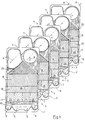
- the plate heat exchanger shown in Fig. 1 comprises two kinds of rectangular, elongated heat transfer plates 1,2 which have been provided with different corrugation patterns by means of pressing.
- the heat transfer plates which are intended to be kept together in a frame (not shown) in a conventional manner, may be provided with rubber gaskets along their edges to delimit flow spaces 3 between them, but as an alternative they could be permanently joined to each other, e.g. through soldering, welding or gluing.
- the heat transfer plates 1 and 2 have been provided with a corrugation pattern of ridges and grooves by means of pressing, the ridges of two adjacent heat transfer plates in the flow spaces 3 crossing and abutting each other to form a number of supporting points between the heat transfer plates.
- Every second flow space 3 forms a passage 4 for evaporation of a fluid, which passage communicates with a fluid inlet 5 extending through a lower portion of the heat transfer plates and an outlet 6 for fluid and generated vapour, which extends through an upper portion of the heat transfer plates.
- Remaining flow spaces form second passages 7 for a heating fluid, which passages communicate with a steam inlet 8 extending through the upper portion of the heat transfer plates, and two condensate outlets 9 extending through the lower portion of the heat transfer plates.
- the heat exchanger shown in Fig. 1 is principally intended for evaporation or concentration of various liquid products by means of climbing film evaporation.
- the long sides of the heat transfer plates 1 and 2 are arranged vertically, and fluid to be evaporated is supplied to the passages 4 at their lower portion and discharged at their upper portion.
- the plate heat exchanger is arranged for use as a falling film evaporator with steam as heating medium supplied at the upper portion of the passages 7 and the condensate produced discharged at the lower portion of the passages 7.
- Each of the heat transfer plates 1 and 2 has a lower distribution portion 15, a heat transferring portion 16, divided in different horizontally extended portions 17, 18 and 19 having different corrugation patterns, and an upper distribution portion 20.
- the lower distribution portion 15 is arranged to convey fluid in each passage 4, essentially vertically upwards from the inlet 5 to the heat transfer portion 16, and in each passage 7, to convey the condensate both vertically downwards and horizontally towards the outlets 9.
- the upper distribution portion is formed in a manner which appears more closely in US 3783090.
- the lower horizontally extended portion 17 is divided into a number of zones 23, 24, 25 and 26 having different corrugation patterns, and being arranged adjacent to each other near to said inlet 5 for the fluid in each of the evaporating passages 4.
- the ridges and grooves in the zones 23, 24, 25 and 26 are directed in such a way that they cooperate to provide a flow resistance for the upwardly flowing fluid and generated vapour in each evaporating passage 4, which gradually decreases from one to the other of the vertical sides of the heat transfer plates.
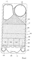
- the heat transfer plates 1 and 2 shown in Figs. 2 and 3 have punched holes at each of their ends. These holes form a port 10A and 10B, respectively, at the bottom, for the fluid to be evaporated, a port 11A and 11B, respectively at the top, for concentrated fluid and generated vapour, a port 12A and 12B, respectively, at the top for heating steam and two ports 13A, 14A and 13B, 14B, respectively, at the bottom, for condensate and eventually uncondensed steam of the heating medium.
- the heat transfer plates 1 and 2 are further provided with lower distribution portions 15A and 15B, respectively, upper distribution portions 20A and 20B, respectively and heat transfer portions 16A and 16B, respectively, which latter are divided in different horizontally extended portions 17A, 18A, 19A and 17B, 18B, 19B, respectively, having different corrugation patterns.
- the lower portions 17A and 17B, respectively, of each plate are divided in different vertically extended zones 23A, 24A, 25A, 26A and 23B, 24B, 25B, 26B, respectively, having different corrugation patterns.
- the heat transfer plate 1 has on one of its sides a number of grooves 21 in which a unitary gasket is received.
- the gasket extends around each of the ports 10A and 10B and around the whole periphery of the plate.
- the heat exchange plate 2 has a number of grooves 22 accommodating a gasket extending around each of the ports 12B, 13B and 14B and around the whole periphery of the plate.
- the gaskets are arranged to seal between adjacent heat transfer plates 1 and 2.
- the gasket grooves can, as an alternative, be formed such that two adjacent plates may be welded together having the bottom of the grooves turned against each other, wherein only alternate plate interspaces are provided with gaskets which in such a case is located in confronting grooves in the adjacent heat transfer plates.
- the ridges and the grooves incline differently against the intended main flow direction of the fluid.
- the gradient decreases from one zone to another from below and upwards.
- Fluid which is to be completely or partly evaporated is supplied into the plate heat exchanger through the fluid inlet 5 which is located in the lower part of the heat transfer plates, and then flows upwards through the passage 4. Fluid is evenly distributed across the width of the heat transfer plates between the lower distribution portions 15A and 15B. Between the heat transfer portions 16A and 16B the fluid first passes the portions 17A and 17B, which include the four zones 23A, 24A, 25A, 26A and 23B, 24B, 25B, 26B, respectively.
- the zones 23A and 23B, located at one vertical side of the plate have a corrugation pattern providing a relatively great flow resistance in the evaporation passages 4 for upwardly flowing fluid, i.e. the ridges of the plates cross each other with a comparatively large intervening angle directed against the flow direction of the fluid.
- the heat transfer between the plates and the fluid becomes relatively efficient and consequently, vapour is generated relatively soon in these portions of the passages 4.
- the ridges and grooves incline differently against the intended main flow direction of the fluid.
- the gradient decreases from one zone to another from one to the other vertical side of each plate.
- an angle a of the plate 1 between the main flow direction of the fluid (shown with a vertical dash and dot line) and the direction of the corrugation ridges is -40° in the zone 23A, -36° in the zone 24A, -30° in the zone 25A and -22° in the zone 26A.
- an angle ⁇ between the flow direction of the fluid and the direction of the corrugating ridges is +40° in the zone 23B, +36° in the zone 24B, +30° in the zone 25B and +22° in the zone 26B.
- the intermediate angle for the intersecting ridges of the plates 1 and 2 will be 80° in the zones 23A and B, 72° in the zones 24A and B, 60° in the zones 25A and B and 44° in the zones 26A and B.
- the average angle will be about 64°.
- Corresponding angle is 50° for the portions 18A and 18B and 40° for the portions 19A and 19B.
- the values given for these angles have been chosen with reference to a certain heat exchange task for the present heat exchanger. Other values can of course be chosen for other heat exchange tasks.
- both of the heat transfer plates 1 and 2 have several horizontal extended portions 17, 18 and 19 with different corrugation patterns and several different zones in the portions 17.
- the different portions of the plates 17A-19A, 23A-26A and 17B-19B, 23B-26B, respectively have been shown located directly opposite to each other, but as an alternative they could be located so that they only partly overlap each other. Also the number of portions and the size of the portions could of course vary.
Landscapes
- Engineering & Computer Science (AREA)
- Physics & Mathematics (AREA)
- Thermal Sciences (AREA)
- Mechanical Engineering (AREA)
- General Engineering & Computer Science (AREA)
- Chemical & Material Sciences (AREA)
- Chemical Kinetics & Catalysis (AREA)
- Heat-Exchange Devices With Radiators And Conduit Assemblies (AREA)
Abstract
Claims (3)
- Echangeur de chaleur à plaques pour évaporer un fluide, comprenant un paquet de plaques de transfert de chaleur (1, 2) rectangulaires, disposées en butée et sensiblement verticalement, délimitant des espaces d'écoulement entre elles et munies de motifs d'ondulations à crêtes et gorges, lesdites crêtes venant en butée les unes contre les autres en se coupant dans au moins une partie de chaque espace d'écoulement et formant un certain nombre de points de support entre plaques de transfert de chaleur adjacentes (1, 2), dans lequel chaque second espace d'écoulement forme un passage d'évaporation (4) pour ledit fluide, lequel passage d'évaporation comprend une entrée (5) pour le fluide à sa portion inférieure et une sortie (6) pour le fluide et la vapeur générée dans sa portion supérieure proche de l'un des côtés verticaux des plaques de transfert de chaleur, et les espaces d'écoulement restants forment des passages (7) pour un fluide de chauffage, lesquels passages comprennent des entrées (8) dans leurs portions supérieures près des autres côtés verticaux des plaques de transfert de chaleur et des sorties (9) dans leurs portions inférieures, caractérisé en ce que dans chaque passage d'évaporation (4), à proximité de son entrée (5) pour le fluide, au moins une plaque de transfert de chaleur (1) est prévue avec plusieurs zones (23A-26A) comportant des motifs d'ondulations différents, disposées latéralement les unes contre les autres en travers de la plaque de transfert de chaleur entre les côtés verticaux de la plaque de transfert de chaleur, les crêtes et les gorges des plaques de transfert de chaleur (1, 2) dans la région desdites zones formant des angles différents avec la direction principale de l'écoulement du fluide dans les passages d'évaporation (4), lesquels angles sont choisis de manière que les crêtes et les gorges, du fait de leurs directions différentes, coopèrent pour déterminer une résistance à l'écoulement dans chaque passage d'évaporation (4), dans sa direction d'écoulement principale, qui diminue graduellement entre lesdits premier et second côtés verticaux de la plaque de transfert de chaleur.
- Echangeur de chaleur à plaques selon la revendication 1, caractérisé en ce que les motifs d'ondulations des plaques de transfert de chaleur sont prévus de manière que la différence de résistance à l'écoulement entre lesdits premier et second côtés verticaux des plaques de transfert de chaleur, provoquée par les crêtes et les gorges du motif d'ondulations, soit concentrée dans la partie inférieure de chaque passage d'évaporation (4) dans lequel le fluide alimenté pendant le fonctionnement n'a pas encore été évaporé de façon notable.
- Echangeur de chaleur à plaques selon la revendication 1 ou 2, caractérisé en ce qu'au moins une plaque de transfert de chaleur sur deux (1) comporte au moins trois zones disposées les unes contre les autres et munies de motifs d'ondulations différents.
Applications Claiming Priority (3)
| Application Number | Priority Date | Filing Date | Title |
|---|---|---|---|
| SE9001633A SE466171B (sv) | 1990-05-08 | 1990-05-08 | Plattfoeraangare daer aatminstone den ena plattan i en foeraangningspassage aer uppdelad i faelt anordnade bredvid varandra mellan plattans laangsidor, vilka faelt uppvisar sinsemellan olika korrugeringsmoenster saa att stroemningsmotstaandet successivt minskar fraan ena sidan till den andra |
| SE9001633 | 1990-05-08 | ||
| PCT/SE1991/000303 WO1991017406A1 (fr) | 1990-05-08 | 1991-04-29 | Evaporateur a plaques |
Publications (2)
| Publication Number | Publication Date |
|---|---|
| EP0485555A1 EP0485555A1 (fr) | 1992-05-20 |
| EP0485555B1 true EP0485555B1 (fr) | 1994-07-06 |
Family
ID=20379402
Family Applications (1)
| Application Number | Title | Priority Date | Filing Date |
|---|---|---|---|
| EP91909728A Expired - Lifetime EP0485555B1 (fr) | 1990-05-08 | 1991-04-29 | Evaporateur a plaques |
Country Status (9)
| Country | Link |
|---|---|
| US (1) | US5226474A (fr) |
| EP (1) | EP0485555B1 (fr) |
| JP (1) | JP2968042B2 (fr) |
| BR (1) | BR9105744A (fr) |
| DE (1) | DE69102755T2 (fr) |
| DK (1) | DK0485555T3 (fr) |
| ES (1) | ES2060386T3 (fr) |
| SE (1) | SE466171B (fr) |
| WO (1) | WO1991017406A1 (fr) |
Families Citing this family (44)
| Publication number | Priority date | Publication date | Assignee | Title |
|---|---|---|---|---|
| DE4142177C2 (de) * | 1991-12-20 | 1994-04-28 | Balcke Duerr Ag | Plattenwärmetauscher |
| SE469669B (sv) * | 1992-01-21 | 1993-08-16 | Alfa Laval Thermal Ab | Foerdelningsmoenster hos plattvaermevaexlare |
| SE505225C2 (sv) | 1993-02-19 | 1997-07-21 | Alfa Laval Thermal Ab | Plattvärmeväxlare och platta härför |
| GB9426208D0 (en) * | 1994-12-23 | 1995-02-22 | British Tech Group Usa | Plate heat exchanger |
| JP3292128B2 (ja) * | 1998-02-27 | 2002-06-17 | ダイキン工業株式会社 | プレート型熱交換器 |
| US6244333B1 (en) | 1998-08-27 | 2001-06-12 | Zeks Air Drier Corporation | Corrugated folded plate heat exchanger |
| US6186223B1 (en) | 1998-08-27 | 2001-02-13 | Zeks Air Drier Corporation | Corrugated folded plate heat exchanger |
| JP3100371B1 (ja) * | 1999-04-28 | 2000-10-16 | 春男 上原 | 蒸発器 |
| DE10013437C1 (de) * | 2000-03-17 | 2001-12-06 | Xcellsis Gmbh | Folienpaket für einen aus Folien aufgebauten Verdampfer |
| SE516416C2 (sv) | 2000-05-19 | 2002-01-15 | Alfa Laval Ab | Plattpaket, värmeöverföringsplatta, plattvärmeväxlaresamt anv ändning av värmeöverföringsplatta |
| SE516537C2 (sv) | 2000-05-19 | 2002-01-29 | Alfa Laval Ab | Plattpaket och plattvärmeväxlare |
| DE10035939A1 (de) * | 2000-07-21 | 2002-02-07 | Bosch Gmbh Robert | Vorrichtung zur Wärmeübertragung |
| SE520702C2 (sv) * | 2001-12-18 | 2003-08-12 | Alfa Laval Corp Ab | Värmeväxlarplatta med minst två korrugeringsområden, plattpaket samt plattvärmeväxlare |
| SE520703C2 (sv) * | 2001-12-18 | 2003-08-12 | Alfa Laval Corp Ab | Värmeväxlarplatta med korrugerat stödområde, plattpaket samt plattvärmeväxlare |
| DE10352880A1 (de) | 2003-11-10 | 2005-06-09 | Behr Gmbh & Co. Kg | Wärmeübertrager, insbesondere Ladeluft-/Kühlmittel-Kühler |
| DE10352881A1 (de) | 2003-11-10 | 2005-06-09 | Behr Gmbh & Co. Kg | Wärmeübertrager, insbesondere Ladeluft-/Kühlmittel-Kühler |
| CN1837718A (zh) * | 2006-03-09 | 2006-09-27 | 缪志先 | 肋板式换热器 |
| CA2584955C (fr) * | 2006-05-15 | 2014-12-02 | Sulzer Chemtech Ag | Melangeur statique |
| CN100516758C (zh) * | 2007-06-12 | 2009-07-22 | 缪志先 | 一种无封条板翅式换热器 |
| SE534306C2 (sv) | 2008-06-17 | 2011-07-05 | Alfa Laval Corp Ab | Värmeväxlarplatta och plattvärmeväxlare |
| US8844610B2 (en) * | 2008-09-18 | 2014-09-30 | Multistack, LLC | Double inlet heat exchanger |
| SE533067C2 (sv) * | 2008-10-03 | 2010-06-22 | Alfa Laval Corp Ab | Plattvärmeväxlare |
| CN102245994B (zh) * | 2008-12-17 | 2015-09-23 | 舒瑞普国际股份公司 | 热交换器的开口 |
| CN102245993A (zh) * | 2008-12-17 | 2011-11-16 | 舒瑞普国际股份公司 | 半岛上的高压开口 |
| JP5106453B2 (ja) * | 2009-03-18 | 2012-12-26 | 三菱電機株式会社 | プレート式熱交換器及び冷凍空調装置 |
| US9557119B2 (en) * | 2009-05-08 | 2017-01-31 | Arvos Inc. | Heat transfer sheet for rotary regenerative heat exchanger |
| NO331474B1 (no) * | 2009-11-13 | 2012-01-09 | Hamworthy Gas Systems As | Installasjon for gjengassing av LNG |
| US8826901B2 (en) * | 2010-01-20 | 2014-09-09 | Carrier Corporation | Primary heat exchanger design for condensing gas furnace |
| SE534765C2 (sv) * | 2010-04-21 | 2011-12-13 | Alfa Laval Corp Ab | Plattvärmeväxlareplatta och plattvärmeväxlare |
| DE102010036654A1 (de) | 2010-07-27 | 2012-03-29 | Peter Rehberg | Plattenwärmeübertrager zum Verdampfen einer Flüssigkeit |
| US9644899B2 (en) * | 2011-06-01 | 2017-05-09 | Arvos, Inc. | Heating element undulation patterns |
| US9395125B2 (en) | 2011-09-26 | 2016-07-19 | Trane International Inc. | Water temperature sensor in a brazed plate heat exchanger |
| FR2982016A1 (fr) * | 2011-10-28 | 2013-05-03 | Tmw | Support d'etalement d'un liquide en ecoulement gravitaire, systeme d'etalement et colonne d'evaporation comprenant un tel support |
| CN102728081A (zh) * | 2012-07-22 | 2012-10-17 | 甘肃蓝科石化高新装备股份有限公司 | 可拆式升膜板式蒸发器 |
| CN104296586A (zh) * | 2013-07-15 | 2015-01-21 | 杭州三花研究院有限公司 | 换热器板片、换热器换热单元以及换热器 |
| LT2957851T (lt) * | 2014-06-18 | 2017-06-26 | Alfa Laval Corporate Ab | Šilumos perdavimo plokštė ir plokštelinis šilumokaitis, apimantis tokią šilumos perdavimo plokštę |
| KR101892549B1 (ko) * | 2016-04-28 | 2018-08-30 | 한국원자력연구원 | 열교환기 및 이를 구비하는 원전 |
| EP3396293A1 (fr) * | 2017-04-26 | 2018-10-31 | Alfa Laval Corporate AB | Plaque de transfert de chaleur et échangeur de chaleur comprenant une pluralité dedites plaques de transfert de chaleur |
| CN108592665A (zh) * | 2018-03-12 | 2018-09-28 | 新乡市特美特热控技术股份有限公司 | 翅片板式换热器 |
| US11486657B2 (en) * | 2018-07-17 | 2022-11-01 | Tranter, Inc. | Heat exchanger heat transfer plate |
| PT3660437T (pt) * | 2018-11-29 | 2021-08-16 | Alfa Laval Corp Ab | Um permutador de placa de calor e uma placa de permuta de calor para tratar uma alimentação tal como água do mar |
| SE544426C2 (en) * | 2019-04-03 | 2022-05-24 | Alfa Laval Corp Ab | A heat exchanger plate, and a plate heat exchanger |
| EP3792581B1 (fr) * | 2019-09-13 | 2023-02-22 | Alfa Laval Corporate AB | Échangeur de chaleur à plaques pour le traitement d'une alimentation de liquide |
| SI4365532T1 (sl) * | 2022-11-01 | 2026-02-27 | Alfa Laval Corporate Ab | Ploščni izmenjevalnik toplote in ploščni izmenjevalnik toplote |
Family Cites Families (6)
| Publication number | Priority date | Publication date | Assignee | Title |
|---|---|---|---|---|
| US2872165A (en) * | 1954-09-04 | 1959-02-03 | Separator Ab | Plate type heat exchanger |
| GB1339542A (en) | 1970-03-20 | 1973-12-05 | Apv Co Ltd | Plate heat exchangers |
| SE411952B (sv) * | 1978-07-10 | 1980-02-11 | Alfa Laval Ab | Vermevexlare innefattande ett flertal i ett stativ inspenda vermevexlingsplattor |
| SE415928B (sv) * | 1979-01-17 | 1980-11-10 | Alfa Laval Ab | Plattvermevexlare |
| SE458805B (sv) * | 1985-06-06 | 1989-05-08 | Reheat Ab | Plattvaermevaexlare, vari varje platta aer uppdelad i fyra omraaden med sinsemellan olika riktning paa korrugeringarna |
| DD245247A1 (de) | 1985-12-24 | 1987-04-29 | Kyffhaeuserhuette Maschf | Waermeuebertragungsplatten |
-
1990
- 1990-05-08 SE SE9001633A patent/SE466171B/sv not_active IP Right Cessation
-
1991
- 1991-04-29 EP EP91909728A patent/EP0485555B1/fr not_active Expired - Lifetime
- 1991-04-29 WO PCT/SE1991/000303 patent/WO1991017406A1/fr not_active Ceased
- 1991-04-29 ES ES91909728T patent/ES2060386T3/es not_active Expired - Lifetime
- 1991-04-29 DK DK91909728.7T patent/DK0485555T3/da active
- 1991-04-29 BR BR919105744A patent/BR9105744A/pt not_active IP Right Cessation
- 1991-04-29 DE DE69102755T patent/DE69102755T2/de not_active Expired - Fee Related
- 1991-04-29 JP JP3509219A patent/JP2968042B2/ja not_active Expired - Fee Related
- 1991-04-29 US US07/761,798 patent/US5226474A/en not_active Expired - Lifetime
Also Published As
| Publication number | Publication date |
|---|---|
| BR9105744A (pt) | 1992-08-04 |
| WO1991017406A1 (fr) | 1991-11-14 |
| DK0485555T3 (da) | 1994-08-01 |
| SE9001633D0 (sv) | 1990-05-08 |
| DE69102755T2 (de) | 1994-10-27 |
| DE69102755D1 (de) | 1994-08-11 |
| ES2060386T3 (es) | 1994-11-16 |
| US5226474A (en) | 1993-07-13 |
| SE9001633L (sv) | 1991-11-09 |
| SE466171B (sv) | 1992-01-07 |
| JPH04506996A (ja) | 1992-12-03 |
| JP2968042B2 (ja) | 1999-10-25 |
| EP0485555A1 (fr) | 1992-05-20 |
Similar Documents
| Publication | Publication Date | Title |
|---|---|---|
| EP0485555B1 (fr) | Evaporateur a plaques | |
| JP2968041B2 (ja) | 板型蒸発器 | |
| EP2304369B1 (fr) | Echangeur de chaleur | |
| RU2110030C1 (ru) | Пластинчатый теплообменник для теплообмена между двумя жидкостями при разных больших расходах | |
| EP0014066B1 (fr) | Echangeur de chaleur du type à plaques | |
| EP0094954B1 (fr) | Plaque d'echangeur de chaleur | |
| US6032470A (en) | Plate heat exchanger | |
| GB2121525A (en) | Plate evaporator or condenser | |
| US4966227A (en) | Plate evaporator | |
| EP0621940B1 (fr) | Modele de repartition d'un echangeur de chaleur a plaques | |
| KR102553541B1 (ko) | 해수와 같은 공급물을 처리하기 위한 플레이트형 열교환기 | |
| AU596305B2 (en) | Falling film liquor heater | |
| KR102553537B1 (ko) | 해수와 같은 공급물을 처리하기 위한 열교환 플레이트 및 플레이트형 열교환기 | |
| JP2004537024A (ja) | 伝熱プレート、プレートパック及びプレート式熱交換器 | |
| JPH04268191A (ja) | ルーバーを有する塔パッキング | |
| JPH0979769A (ja) | ろう付けプレートを備えた熱交換器及び同熱交換器における二相の流体の処理方法 | |
| JPH10197169A (ja) | デフレグメータ | |
| JP2022533630A (ja) | プレート熱交換器、熱交換プレートおよび海水などのフィードを処理する方法 |
Legal Events
| Date | Code | Title | Description |
|---|---|---|---|
| PUAI | Public reference made under article 153(3) epc to a published international application that has entered the european phase |
Free format text: ORIGINAL CODE: 0009012 |
|
| 17P | Request for examination filed |
Effective date: 19911220 |
|
| AK | Designated contracting states |
Kind code of ref document: A1 Designated state(s): DE DK ES FR GB IT SE |
|
| 17Q | First examination report despatched |
Effective date: 19930408 |
|
| GRAA | (expected) grant |
Free format text: ORIGINAL CODE: 0009210 |
|
| RAP1 | Party data changed (applicant data changed or rights of an application transferred) |
Owner name: ALFA-LAVAL THERMAL AB |
|
| ITF | It: translation for a ep patent filed | ||
| AK | Designated contracting states |
Kind code of ref document: B1 Designated state(s): DE DK ES FR GB IT SE |
|
| REG | Reference to a national code |
Ref country code: DK Ref legal event code: T3 |
|
| REF | Corresponds to: |
Ref document number: 69102755 Country of ref document: DE Date of ref document: 19940811 |
|
| ET | Fr: translation filed | ||
| REG | Reference to a national code |
Ref country code: ES Ref legal event code: FG2A Ref document number: 2060386 Country of ref document: ES Kind code of ref document: T3 |
|
| EAL | Se: european patent in force in sweden |
Ref document number: 91909728.7 |
|
| PLBE | No opposition filed within time limit |
Free format text: ORIGINAL CODE: 0009261 |
|
| STAA | Information on the status of an ep patent application or granted ep patent |
Free format text: STATUS: NO OPPOSITION FILED WITHIN TIME LIMIT |
|
| 26N | No opposition filed | ||
| REG | Reference to a national code |
Ref country code: FR Ref legal event code: TP |
|
| REG | Reference to a national code |
Ref country code: FR Ref legal event code: GC |
|
| REG | Reference to a national code |
Ref country code: GB Ref legal event code: IF02 |
|
| REG | Reference to a national code |
Ref country code: GB Ref legal event code: 732E |
|
| REG | Reference to a national code |
Ref country code: FR Ref legal event code: RG |
|
| PGFP | Annual fee paid to national office [announced via postgrant information from national office to epo] |
Ref country code: ES Payment date: 20090508 Year of fee payment: 19 Ref country code: DK Payment date: 20090415 Year of fee payment: 19 |
|
| PGFP | Annual fee paid to national office [announced via postgrant information from national office to epo] |
Ref country code: DE Payment date: 20090428 Year of fee payment: 19 Ref country code: IT Payment date: 20090424 Year of fee payment: 19 Ref country code: FR Payment date: 20090417 Year of fee payment: 19 Ref country code: SE Payment date: 20090407 Year of fee payment: 19 |
|
| PGFP | Annual fee paid to national office [announced via postgrant information from national office to epo] |
Ref country code: GB Payment date: 20090429 Year of fee payment: 19 |
|
| EUG | Se: european patent has lapsed | ||
| REG | Reference to a national code |
Ref country code: DK Ref legal event code: EBP |
|
| GBPC | Gb: european patent ceased through non-payment of renewal fee |
Effective date: 20100429 |
|
| REG | Reference to a national code |
Ref country code: FR Ref legal event code: ST Effective date: 20101230 |
|
| PG25 | Lapsed in a contracting state [announced via postgrant information from national office to epo] |
Ref country code: DE Free format text: LAPSE BECAUSE OF NON-PAYMENT OF DUE FEES Effective date: 20101103 |
|
| PG25 | Lapsed in a contracting state [announced via postgrant information from national office to epo] |
Ref country code: GB Free format text: LAPSE BECAUSE OF NON-PAYMENT OF DUE FEES Effective date: 20100429 Ref country code: IT Free format text: LAPSE BECAUSE OF NON-PAYMENT OF DUE FEES Effective date: 20100429 |
|
| PG25 | Lapsed in a contracting state [announced via postgrant information from national office to epo] |
Ref country code: DK Free format text: LAPSE BECAUSE OF NON-PAYMENT OF DUE FEES Effective date: 20100503 |
|
| REG | Reference to a national code |
Ref country code: ES Ref legal event code: FD2A Effective date: 20110708 |
|
| PG25 | Lapsed in a contracting state [announced via postgrant information from national office to epo] |
Ref country code: ES Free format text: LAPSE BECAUSE OF NON-PAYMENT OF DUE FEES Effective date: 20110628 |
|
| PG25 | Lapsed in a contracting state [announced via postgrant information from national office to epo] |
Ref country code: ES Free format text: LAPSE BECAUSE OF NON-PAYMENT OF DUE FEES Effective date: 20100430 |
|
| PG25 | Lapsed in a contracting state [announced via postgrant information from national office to epo] |
Ref country code: FR Free format text: LAPSE BECAUSE OF NON-PAYMENT OF DUE FEES Effective date: 20100430 |
|
| PG25 | Lapsed in a contracting state [announced via postgrant information from national office to epo] |
Ref country code: SE Free format text: LAPSE BECAUSE OF NON-PAYMENT OF DUE FEES Effective date: 20100430 |