EP0485629B1 - Methode und gerät zum testen von mehradrigen optischen fiberkabeln mit optischen anschlüssen - Google Patents
Methode und gerät zum testen von mehradrigen optischen fiberkabeln mit optischen anschlüssen Download PDFInfo
- Publication number
- EP0485629B1 EP0485629B1 EP91910197A EP91910197A EP0485629B1 EP 0485629 B1 EP0485629 B1 EP 0485629B1 EP 91910197 A EP91910197 A EP 91910197A EP 91910197 A EP91910197 A EP 91910197A EP 0485629 B1 EP0485629 B1 EP 0485629B1
- Authority
- EP
- European Patent Office
- Prior art keywords
- light
- fiber cable
- optical fiber
- optical fibers
- inspection
- Prior art date
- Legal status (The legal status is an assumption and is not a legal conclusion. Google has not performed a legal analysis and makes no representation as to the accuracy of the status listed.)
- Expired - Lifetime
Links
- 239000013307 optical fiber Substances 0.000 title claims abstract description 143
- 230000003287 optical effect Effects 0.000 title claims abstract description 30
- 238000000034 method Methods 0.000 title claims description 18
- 238000012360 testing method Methods 0.000 title abstract 5
- 230000000903 blocking effect Effects 0.000 claims abstract description 53
- 238000007689 inspection Methods 0.000 claims abstract description 53
- 239000000835 fiber Substances 0.000 claims description 26
- 239000004973 liquid crystal related substance Substances 0.000 claims description 8
- 238000005259 measurement Methods 0.000 abstract 1
- 230000002950 deficient Effects 0.000 description 2
- 238000001514 detection method Methods 0.000 description 1
- 230000004048 modification Effects 0.000 description 1
- 238000012986 modification Methods 0.000 description 1
- 238000011179 visual inspection Methods 0.000 description 1
Images

Classifications
-
- G—PHYSICS
- G01—MEASURING; TESTING
- G01M—TESTING STATIC OR DYNAMIC BALANCE OF MACHINES OR STRUCTURES; TESTING OF STRUCTURES OR APPARATUS, NOT OTHERWISE PROVIDED FOR
- G01M11/00—Testing of optical apparatus; Testing structures by optical methods not otherwise provided for
- G01M11/30—Testing of optical devices, constituted by fibre optics or optical waveguides
- G01M11/33—Testing of optical devices, constituted by fibre optics or optical waveguides with a light emitter being disposed at one fibre or waveguide end-face, and a light receiver at the other end-face
Definitions
- the present invention relates to a method and an apparatus for inspecting the quality of a ribbon fiber cable having an optical connector.
- Optical fiber cables include single-core optical fiber cables having a single optical fiber and ribbon fiber cables having a number of optical fibers. In the case of both of these optical fiber cables, an optical connector is attached to the ends for connection to other optical fiber cables. In this case, it is necessary to examine the connection loss caused by the attachment of the optical connectors.
- connection loss When inspecting a ribbon fiber cable after attachment of an optical connector, in the prior art the inspection of the connection loss and the inspection of the arrangement have been performed as separate processes.
- the arrangement of the optical fibers was inspected by inputting a light beam from one end of the ribbon fiber cable for each optical fiber and examining by visual inspection or an image sensor the order of the light beam emitted from the other end of the optical fiber cable for each optical fiber.
- the connection loss was inspected by inputting a light beam from one end of the ribbon fiber cable for each optical fiber and measuring by a light power meter the intensity of the light beam emitted from the other end of the optical fiber cable for each optical fiber.
- the present invention was made to eliminate the disadvantages of the prior art and has as its object the provision of a method and an apparatus for inspecting a ribbon fiber cable having an optical connector which enable simultaneous inspection of the connection loss and inspection of the arrangement, facilitate the inspection work, and reduce the inspection time.
- the method of inspection of the present invention is characterized by connecting to one end of an optical fiber cable a light inputting means for inputting a light beam in a predetermined order to each of the inputting side ends of the optical fibers, disposing at the other end of the optical fiber cable a light receiving means in a predetermined distance away from the emitting side ends of the optical fibers, disposing between the emitting side ends of the optical fibers and the light receiving means a light passing/blocking means for selectively allowing, for each light beam emitted from the emitting side ends, the passing or blocking of light emitted from the emitting side ends and inputted to the light receiving means, passing or blocking in a predetermined order by the above-mentioned light passing/blocking means the light beam inputted and emitted for each optical fiber in a predetermined order, and using the light receiving means to detect the presence of irradiation of light and the luminous quantity of the light beam so as to simultaneously perform inspection of the order of arrangement of the optical fiber
- the inspection apparatus of the present invention is characterized by comprising a light inputting means which is connected to one end of an optical fiber cable and which inputs a light beam in a predetermined order to each of the inputting side ends of the optical fibers, a light receiving means disposed at the other end of the optical fiber cable in a predetermined distance away from the emitting side ends of the optical fibers, and a light passing/blocking means which is disposed between the emitting side ends of the optical fibers and the light receiving means and which selectively allows, for each light beam emitted from the emitting side ends, the passing or blocking of the light beam emitted from the emitting side ends and inputted to the light receiving means, wherein the light beam inputted and emitted for each optical fiber in a predetermined order is passed or blocked by the above-mentioned light passing/blocking means in a predetermined order and the light receiving means is used to detect the presence of irradiation of the light beam and the luminous quantity of the light beam so as to simultaneously perform inspection of the order of the
- the light inputting apparatus is connected to one end of the ribbon fiber cable and a light beam is inputted from there for each optical fiber in a predetermined order.
- the inputted light beam is emitted from the emitting ends of the optical fibers toward the light receiving means.
- the light passing/blocking means selectively passes or blocks the light beam inputted and emitted in a predetermined order for each optical fiber in a predetermined order corresponding to the optical fibers where the light is inputted to.
- the light beam emitted from the emitting side ends of the optical fibers in a predetermined order passed or blocked by the light passing/blocking means in the order corresponding to that order, it is detected whether the arrangement of the optical fibers is normal or not. Further, when the light beam emitted from the optical fibers is received by the light receiving means, the luminous quantity of light is simultaneously measured, so it is possible to measure the connection loss of the light beam due to the connection of an optical connector.
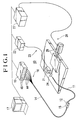
- Figure 1 is an overall structural view of an inspection apparatus for an optical fiber cable according to one embodiment of the present invention
- Fig. 2 is a perspective view of a light passing/blocking means used for the inspection apparatus
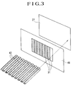
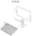
- Fig. 3 and Fig. 4 are perspective views showing other embodiments of the light passing/blocking means used in inspection apparatuses according to other embodiments of the present invention.
- the inspection apparatus 40 of the present embodiment is comprised so as to inspect a ribbon fiber cable 11 as the object of inspection.
- the inspection apparatus 40 has a light inputting means 16, a light passing/blocking means 28, and a light receiving means 23.
- the ribbon fiber cable 11 which is inspected has a plurality of optical fibers 42 (see Fig. 2) arranged inside it. At one end of the ribbon fiber cable 11, there is attached in advance an optical connector 12. At the other end, as shown in Fig. 2, the ends of the optical fibers 42 incorporated therein are exposed in a linear array. In this embodiment, the end of the optical fiber cable where the optical connector 12 is mounted becomes the light inputting side end, while the side where the optical fibers 42 are exposed becomes the light emitting side end.
- the optical fiber cable 14 having the optical connector 15 is connected to a light emitter 13 and serves as the light inputting means 16 for the optical fiber cable 11 being inspected.
- the number of the optical fibers incorporated in the optical fiber cable 14 is the same as the number of cores of the optical fiber cable 11 being inspected.
- the numbers of optical paths connected by the optical connectors 2 and 15 attached to the two cables also match.
- the optical fibers 44 incorporated therein are exposed.
- the ends of the optical fibers 44 are connected to light emitting output units 46 of the light emitter 13.
- the light emitting output units 46 have light emitting diodes attached to them.
- the light emitting diodes emit light beams in a predetermined order, whereby each light beam is output to the optical fibers 44 in a predetermined order.
- the case may be considered of making the light emitting diodes emit each light beam in order from the left starting with the left most light emitting diode.
- the order of emission of the light beam emitting diodes is controlled by a control means 17.
- the light emitting side end of the ribbon fiber cable 11 being inspected is disposed so as to face the light receiving sensor 21 at a predetermined position away from the same.
- Light beam emitted from any of the optical fibers 42 in the ribbon fiber cable 11 enters the light receiving sensor 21, where the luminous quantity of the light is measured by the light power meter 22.
- the light receiving sensor 21 and the light power sensor 22 constitute the light receiving means 23 in the present embodiment.
- the light receiving sensor 21 is a sensor which can receive all of the light beam emitted from the emitting side ends of the optical fibers 42. It may be constituted by a single light receiving sensor or may be constituted by a number of light receiving sensors.
- a selective passage member 24 such as shown in Fig. 2.
- the selective passage member 24 is constituted in this embodiment by a slitted disk in which a slit-shaped passage hole 25 allowing passage of only light beam emitted from one of the optical fibers 42 is formed.
- the selective passage member 24 is designed to be moved one pitch of the fibers at a time in the direction of arrangement of the optical fibers 42 by a pitch feed mechanism 26 shown in Fig. 1.
- the pitch feed mechanism 26 is constituted, for example, by a pulse motor and a mechanism for converting the rotation of the same to linear motion and operates on the basis of control pulses from the feed controller 27.
- the selective passage member 24, the pitch feed mechanism 26, and the feed controller 27 constitutes a light passing/blocking means 28.
- the light inputting means 16 and the light passing/blocking means 28 operate synchronously by a controller 17. That is, when a light beam is inputted in order by the light inputting means 16 from one side of the optical fibers 42 in the ribbon fiber cable 11, the slit-shaped passage hole 25 moves one pitch at a time by the light passing/blocking means 28 in the same order. Therefore, if a light beam is inputted to the light receiving sensor 21 each time when the passage hole 25 is moved one pitch, it is possible to confirm that the optical fibers are connected to the optical connector 12 in the normal arrangement. Further, if the luminous quantity of the light inputted to the light receiving sensor 21 at that time is measured, it is possible to simultaneously measure the connection loss of light due to the connection of the optical connector 12 to the optical fiber cable 11.
- the position of the passage hole 25 and the positions of the optical fibers 42 emitting a light beam deviate and the emitted light beam is blocked by the selective passage member 24 so the light beam is not inputted to the light receiving sensor 21.
- This enables detection of defective arrangement of the optical fibers.
- a slit-shaped passage hole as the light passage hole 25 of the light passing/blocking means, but the shape of the passage hole 25 is not limited to the same and the hole may be a pinhole-shaped hole as well. If use is made of a pinhole-shaped passage hole, it is possible to apply the present invention to the inspection of ribbon fiber cables other than ribbon fiber cables where the optical fibers are arranged in a straight line.
- the light passing/blocking means need only selectively pass and block a light beam, so as shown in Fig. 3, use may also be made of a selective passage member 48 which has an array of a liquid crystal films 31, which become transparent or opaque upon with application of voltage, at a pitch corresponding to the optical fibers 42 of the ribbon fiber cable 11.
- this selective passage member 48 by controlling the voltage applied to the liquid crystal films 31, for example, by applying voltage successively from the liquid crystal film 31 of the end, it is possible to successively make only the liquid crystal film 31 to which voltage is applied transparent and to synchronize with the light beam successively emitted from the optical fibers 42.
- the selective blocking member 32 shown in Fig. 4 is illustrated as another embodiment of the light passing/blocking means.
- the selective blocking member 32 is constituted so as to block only the light beam emitting from the emitting side end of one of the optical fibers 42 to the light receiving sensor 21. Further, the blocking member 32 is controlled so as to successively move one pitch of the optical fibers at a time in the lateral direction in synchronization with the light beam successively emitted from the optical fibers 42. In the case of this embodiment, if the blocking member 32 is moved one pitch in the lateral direction from the state shown in Fig. 4, for example, the light receiving sensor 21 changes from a state of not receiving light to a state of receiving light.
- a method of inspection and an inspection apparatus constituted so that it is possible to input in advance light beams to the inputting side ends of all of the optical fibers 42 in a ribbon fiber cable, modulate in a predetermined order the light beam inputted to each of the optical fibers 42, and pass in a predetermined order the light beam modulated and emitted in a predetermined order for each of the optical fibers 42 using the above-mentioned selective passage members 24 and 48, also fall in the scope of the present invention.
Landscapes
- Physics & Mathematics (AREA)
- Optics & Photonics (AREA)
- Chemical & Material Sciences (AREA)
- Analytical Chemistry (AREA)
- General Physics & Mathematics (AREA)
- Testing Of Optical Devices Or Fibers (AREA)
- Optical Couplings Of Light Guides (AREA)
- Mechanical Coupling Of Light Guides (AREA)
Claims (14)
- Verfahren zur Untersuchung eines Glasfaser-Bandkabels mit einem optischen Verbinder (12), der an mindestens einem Ende befestigt ist, welches die Schritte aufweist:
Verbinden einer Lichteinspeiseeinrichtung (16) mit einem Ende eines Glasfaserkabels (11) zum Einspeisen von Lichtstrahlen in einer vorgegebenen Reihenfolge in jedes der einspeiseseitigen Enden der Glasfasern (42),
Einrichten einer Lichtempfangseinrichtung (23) an dem anderen Ende des Glasfaserkabels (11) in einem vorgegebenen Abstand von dem ausstrahlungsseitigen Ende der Glasfasern entfernt;
Einrichten einer Lichtdurchlaß-/ -sperreinrichtung (28) zwischen den ausstrahlungsseitigen Enden der Glasfasern (42) und den Lichtempfangseinrichtungen (23), um ausgewählt für jeden von den ausstrahlungsseitigen Enden ausgestrahlten Lichtstrahl das Durchlassen oder Sperren des von den ausstrahlungsseitigen Enden ausgesendeten und der Lichtempfangseinrichtung (23) eingespeisten Lichts zu ermöglichen,
Durchlassen oder Sperren eines Lichtstrahls, der für jede Glasfaser in einer vorgegebenen Reihenfolge über die obengenannte Lichtdurchlaß-/ -sperreinrichtung (28) in einer vorgegebenen Reihenfolge eingespeist und ausgestrahlt worden ist, und Verwenden der Lichtempfangsmittel (23), um das Vorhandensein einer Bestrahlung mit Licht und die Lichtmenge des Lichts festzustellen, um gleichzeitig eine Untersuchung der Reihenfolge der Zusammenstellung der Glasfasern (42) und die Untersuchung des Verbindungsverlustes des Verbinders (12) durchzuführen. - Verfahren zur Untersuchung eines Glasfaser-Bandkabels mit einem optischen Verbinder (12), der an mindestens einem Ende befestigt ist, welches die Schritte aufweist:
Verbinden einer Lichteinspeiseeinrichtung (16) mit einem Ende eines Glasfaserkabels (11) zur Modulation eines Lichtstrahls in einer vorgegebenen Reihenfolge für jedes der einspeiseseitigen Enden der Glasfasern (42),
Einrichten einer Lichtempfangseinrichtung (23) an dem anderen Ende des Glasfaserkabels (11) in einem vorgegebenen Abstand von dem ausstrahlungsseitigen Ende der Glasfasern entfernt;
Einrichten einer Lichtdurchlaß-/ -sperreinrichtung (28) zwischen den ausstrahlungsseitigen Enden der Glasfasern (42) und den Lichtempfangseinrichtungen (23), um ausgewählt für jeden von den ausstrahlungsseitigen Enden ausgestrahlten Lichtstrahl das Durchlassen oder Sperren des von den ausstrahlungsseitigen Enden ausgesendeten und der Lichtempfangseinrichtung (23) eingespeisten Lichts zu ermöglichen,
Durchlassen eines modulierten und ausgestrahlten Lichtstrahls für jede Glasfaser in einer vorgegebenen Reihenfolge über die obengenannte Lichtdurchlaß-/ -sperreinrichtung (28) in einer vorgegebenen Reihenfolge, und Verwenden der Lichtempfangsmittel (23), um das Vorhandensein einer Bestrahlung mit Licht und die Lichtmenge des Lichts festzustellen, um gleichzeitig eine Untersuchung der Reihenfolge der Zusammenstellung der Glasfasern (42) und die Untersuchung des Verbindungsverlustes des Verbinders (12) zu untersuchen. - Verfahren zur Untersuchung eines Glasfaserkabels nach Anspruch 1 oder 2, bei welchem die Lichtempfangseinrichtung (23) einen Lichtempfangssensor (21) besitzt, welcher die gesamten von den ausstrahlungsseitigen Enden ausgestrahlten Lichtstrahlen empfangen kann.
- Verfahren zur Untersuchung eines Glasfaserkabels nach einem der Ansprüche 1 bis 3, bei welchem die Lichtdurchlaß-/ -sperreinrichtung ein Auswahldurchlaßglied (24), in welchem ein Durchlaßloch (25) zur Ermöglichung des Durchgangs nur des von dem ausstrahlungsseitigen Ende von einer der Glasfasern (42) ausgestrahlten Lichts zu der Lichtempfangseinrichtung (23) ausgebildet ist und einen Lochabstandsvorschubmechanismus (26) besitzt, welcher das Auswahldurchlaßglied (24) um einen vorgegebenen Lochabstand bewegt, um den Lichtstrahl, welcher durch das Durchlaßloch (25) hindurchtreten kann, zu wechseln.
- Verfahren zur Untersuchung eines Glasfaserkabels nach einem der Ansprüche 1 bis 3, bei welchem die Lichtdurchlaß-/ -sperreinrichtung ein Auswahldurchlaßglied (48) besitzt, welches in einem Lochabstand entsprechend den ausstrahlungsseitigen Enden der Glasfasern (42) angeordnete Flüssigkristallfilme (31) besitzt, welche durch Anlegen einer Spannung lichtdurchlässig oder lichtundurchlässig werden.
- Verfahren zur Untersuchung eines Glasfaserkabels nach einem der Ansprüche 1 oder 3, bei welchem die Lichtdurchlaß-/ -sperreinrichtung ein Auswahlsperrglied (32), welches nur das von dem ausstrahlungsseitigen Ende eines der Glasfasern (42) zu der Lichtempfangseinrichtung (23) ausgestrahlte Licht sperrt, und einen Lochabstandsvorschubmechanismus (26) besitzt, welcher das Auswahlsperrglied (32) um einen vorgegebenen Lochabstand bewegt, um den Lichtstrahl, welcher durch das Auswahlsperrglied (32) gesperrt wird, zu wechseln.
- Verfahren zur Untersuchung eines Glasfaserkabels nach einem der Ansprüche 1 bis 6, dadurch gekennzeichnet, daß ein Verbinder eines Glasfaserkabels (14) zur Einspeisung von Untersuchungslichtstrahlen, deren Verbindungsverlust bereits bekannt ist, mit einem Ende des Glasfaserkabels, welches einen daran befestigten optischen Verbinder aufweist und in welches ein Lichtstrahl durch das Glasfaserkabel (14) zur Einspeisung von Untersuchungslichtstrahlen in jede der Glasfasern des zu untersuchenden Glasfaserkabels eingespeist wird, verbunden ist.
- Vorrichtung zur Untersuchung eines Glasfaser-Bandkabels mit einem optischen Verbinder (12), der an mindestens einem Ende befestigt ist, wobei die Vorrichtung umfaßt:
eine Lichteinspeiseeinrichtung (16), welche mit einen Ende eines Glasfaserkabels (11) verbunden ist, und welche eingerichtet ist, um in jedes der einspeiseseitigen Enden der Glasfasern (42) Lichtstrahlen in einer vorgegebenen Reihenfolge einzuspeisen,
eine an dem anderen Ende des Glasfaserkabels (11) in einem vorgegebenen Abstand von den ausstrahlungsseitigen Enden der Glasfasern (42) entfernt angeordnete Lichtempfangseinrichtung (23), und
eine Lichtdurchlaß-/ -sperreinrichtung (28), welche zwischen den ausstrahlungsseitigen Enden der Glasfasern (42) und der Lichtempfangseinrichtung (23) angeordnet ist, und welche ausgewählt für jeden von den ausstrahlungsseitigen Enden ausgestrahlten Lichtstrahl das Durchlassen oder Sperren des von den ausstrahlungsseitigen Enden ausgestrahlten und der Lichtempfangseinrichtung (23) eingespeisten Lichts ermöglicht, und Steuermittel (17, 27, 26), die derart angeordnet sind, daß während der Benutzung der für jede Glasfaser in einer vorgegebenen Reihenfolge eingespeiste und ausgestrahlte Lichtstrahl durch die obengenannte Lichtdurchlaß-/ -sperreinrichtung (28) in einer vorgegebenen Reihenfolge durchgelassen oder gesperrt wird, und die Lichtempfangsmittel (23) das Vorhandensein einer Abstrahlung des Lichtstrahls und die Lichtmenge des Lichtstrahls feststellt, um gleichzeitig eine Untersuchung der Reihenfolge der Zusammenstellung der Glasfasern (42) und die Untersuchung des Verbindungsverlustes des Verbinders (12) durchzuführen. - Vorrichtung zur Untersuchung eines Glasfaser-Bandkabels mit einem optischen Verbinder (12), der an mindestens einem Ende befestigt ist, wobei die Vorrichtung umfaßt:
eine Lichteinspeiseeinrichtung (16), welche mit einem Ende eines Glasfaserkabels (11) verbunden ist, und welche eingerichtet ist, um an jedem der einspeiseseitigen Enden der Glasfasern (42) eingespeiste Lichtstrahlen in einer vorgegebenen Reihenfolge zu modulieren,
eine an dem anderen Ende des Glasfaserkabels (11) in einem vorgegebenen Abstand von den ausstrahlungsseitigen Enden der Glasfasern (42) entfernt angeordnete Lichtempfangseinrichtung (23), und
eine Lichtdurchlaß-/ -sperreinrichtung (28), welche zwischen den ausstrahlungsseitigen Enden der Glasfasern (42) und der Lichtempfangseinrichtung (23) angeordnet ist, und welche ausgewählt für jeden von den ausstrahlungsseitigen Enden ausgestrahlten Lichtstrahl das Durchlassen oder Sperren des von den ausstrahlungsseitigen Enden ausgestrahlten und der Lichtempfangseinrichtung (23) eingespeisten Lichts ermöglicht, und Steuermittel (17, 27, 26), die derart angeordnet sind, daß während der Benutzung der für jede Glasfaser in einer vorgegebenen Reihenfolge eingespeiste und ausgestrahlte Lichtstrahl durch die obengenannte Lichtdurchlaß-/ -sperreinrichtung (28) in einer vorgegebenen Reihenfolge durchgelassen oder gesperrt wird, und die Lichtempfangsmittel (23) das Vorhandensein einer Abstrahlung des Lichtstrahls und die Lichtmenge des Lichtstrahls feststellt, um gleichzeitig eine Untersuchung der Reihenfolge der Zusammenstellung der Glasfasern (42) und die Untersuchung des Verbindungsverlustes des Verbinders (12) durchzuführen. - Untersuchungsvorrichtung eines Glasfaser-Bandkabels nach Anspruch 8 oder 9, bei welchem die Lichtempfangseinrichtung (23) einen Lichtempfangssensor (21) besitzt, welcher die gesamten von den ausstrahlungsseitigen Enden ausgestrahlten Lichtstrahlen empfangen kann.
- Untersuchungsvorrichtung eines Glasfaser-Bandkabels nach einem der Ansprüche 8 bis 10, bei welcher die Lichtdurchlaß-/ -sperreinrichtung ein Auswahldurchlaßglied (24), in welchem ein Durchlaßloch (25) zur Ermöglichung des Durchgangs nur des von dem ausstrahlungsseitigen Ende von einer der Glasfasern (42) ausgestrahlten Lichts zu der Lichtempfangseinrichtung (23) ausgebildet ist, und einen Lochabstandsvorschubmechanismus (26) besitzt, welcher das Auswahldurchlaßglied (24) um einen vorgegebenen Lochabstand bewegt, um den Lichtstrahl, welcher durch das Durchlaßloch (25) hindurchtreten kann, zu wechseln.
- Untersuchungsvorrichtung eines Glasfaser-Bandkabels nach einem der Ansprüche 8 bis 10, bei welcher die Lichtdurchlaß-/ -sperreinrichtung ein Auswahldurchlaßglied (48) besitzt, welches in einem Lochabstand entsprechend den ausstrahlungsseitigen Enden der Glasfasern (42) angeordnete Flüssigkristallfilme (31) besitzt, welche durch Anlegen einer Spannung lichtdurchlässig oder lichtundurchlässig werden,.
- Untersuchungsvorrichtung eines Glasfaser-Bandkabels nach Anspruch 8 oder 10, bei welcher die Lichtdurchlaß-/ -sperreinrichtung ein Auswahlsperrglied (32), welches nur das von dem ausstrahlungsseitigen Ende eines der Glasfasern (42) zu der Lichtempfangseinrichtung (23) ausgestrahlte Licht sperrt, und einen Lochabstandsvorschubmechanismus (26) besitzt, welcher das Auswahlsperrglied (32) um einen vorgegebenen Lochabstand bewegt, um den Lichtstrahl, welcher durch das Auswahlsperrglied (32) gesperrt wird, zu wechseln.
- Untersuchungsvorrichtung eines Glasfaser-Bandkabels nach einem der Ansprüche 8 bis 13, dadurch gekennzeichnet, daß die Lichteinspeiseeinrichtung (16) ein Glasfaserkabel (14) zur Eingabe von Untersuchungslichtstrahlen besitzt, welches mit einem Ende des Glasfaserkabels (11) an der Seite, wo der optische Verbinder befestigt ist, verbunden ist, und dessen Verbindungsverlust bereits bekannt ist, und einen Lichtstrahl durch das Glasfaserkabel (14) zur Einspeisung von Untersuchungslichtstrahlen für jede der Glasfasern (42) des zu untersuchenden Glasfaserkabels (11) einspeist.
Applications Claiming Priority (3)
| Application Number | Priority Date | Filing Date | Title |
|---|---|---|---|
| JP2144397A JP3009426B2 (ja) | 1990-06-04 | 1990-06-04 | 光コネクタ付き多心光ファイバの検査装置 |
| JP144397/90 | 1990-06-04 | ||
| PCT/JP1991/000747 WO1991019179A1 (fr) | 1990-06-04 | 1991-06-04 | Procede et dispositif servant a tester des cables a fibres optiques multiconducteurs equipes de raccords optiques |
Publications (3)
| Publication Number | Publication Date |
|---|---|
| EP0485629A1 EP0485629A1 (de) | 1992-05-20 |
| EP0485629A4 EP0485629A4 (en) | 1993-04-07 |
| EP0485629B1 true EP0485629B1 (de) | 1995-02-22 |
Family
ID=15361211
Family Applications (1)
| Application Number | Title | Priority Date | Filing Date |
|---|---|---|---|
| EP91910197A Expired - Lifetime EP0485629B1 (de) | 1990-06-04 | 1991-06-04 | Methode und gerät zum testen von mehradrigen optischen fiberkabeln mit optischen anschlüssen |
Country Status (4)
| Country | Link |
|---|---|
| EP (1) | EP0485629B1 (de) |
| JP (1) | JP3009426B2 (de) |
| DE (1) | DE69107577D1 (de) |
| WO (1) | WO1991019179A1 (de) |
Cited By (1)
| Publication number | Priority date | Publication date | Assignee | Title |
|---|---|---|---|---|
| US6831738B2 (en) * | 2001-06-26 | 2004-12-14 | Adc Telecommunications, Inc. | Method and apparatus for inspecting end surfaces on optical connectors |
Families Citing this family (13)
| Publication number | Priority date | Publication date | Assignee | Title |
|---|---|---|---|---|
| ATE164225T1 (de) * | 1992-07-30 | 1998-04-15 | Siemens Ag | Einrichtung für messungen an lichtwellenleitern und verfahren zur durchführung der messung |
| US6456369B1 (en) * | 1999-01-29 | 2002-09-24 | Ando Electric Co., Ltd. | Multi-core optical fiber inspecting method and apparatus |
| EP1070949A1 (de) * | 2000-04-07 | 2001-01-24 | Agilent Technologies | Messung an Ausgängen einer mehrtoringen Faseroptischen Vorrichtung |
| RU2187791C1 (ru) * | 2001-04-27 | 2002-08-20 | Закрытое Акционерное Общество "Связьстройдеталь" | Способ испытания муфт оптических кабелей на срок службы |
| RU2188405C1 (ru) * | 2001-08-24 | 2002-08-27 | Закрытое Акционерное Общество "Связьстройдеталь" | Способ испытания на сохраняемость комплекта монтажных деталей для монтажа муфт кабелей связи, в том числе оптических |
| EP1354709B1 (de) | 2002-04-16 | 2006-06-28 | Seiko Epson Corporation | Detektor für Tintenpatrone, damit versehenerTintenstrahldrucker und dadurch aufgefundene Tintenpatrone |
| JP4952633B2 (ja) * | 2008-03-29 | 2012-06-13 | ブラザー工業株式会社 | インクカートリッジ装着装置 |
| JP4883166B2 (ja) * | 2009-10-23 | 2012-02-22 | ブラザー工業株式会社 | インクカートリッジ及びインクジェットプリンタ |
| JP5393408B2 (ja) * | 2009-11-10 | 2014-01-22 | 株式会社フジクラ | 光ファイバ検査方法、および光ファイバ検査装置 |
| AT14573U1 (de) * | 2014-06-26 | 2016-01-15 | Secop Austria Gmbh | Stator-Anordnung für einen Einphasen-Induktionsmotor |
| JP6507084B2 (ja) * | 2015-11-17 | 2019-04-24 | 日本電信電話株式会社 | 光ファイバテープ心線モニタ用受光装置、光ファイバテープ心線モニタ方法、及び光回線モニタ方法 |
| JP2018063160A (ja) * | 2016-10-12 | 2018-04-19 | 富士通株式会社 | 検査装置および検査方法 |
| CN113125110A (zh) * | 2021-04-09 | 2021-07-16 | 国网山东省电力公司安丘市供电公司 | 一种odf光芯位序快速核查装置及方法 |
Family Cites Families (1)
| Publication number | Priority date | Publication date | Assignee | Title |
|---|---|---|---|---|
| JPS55163425A (en) * | 1979-06-06 | 1980-12-19 | Nippon Telegr & Teleph Corp <Ntt> | Photometry of multi-core connection for optical fiber |
-
1990
- 1990-06-04 JP JP2144397A patent/JP3009426B2/ja not_active Expired - Fee Related
-
1991
- 1991-06-04 WO PCT/JP1991/000747 patent/WO1991019179A1/ja not_active Ceased
- 1991-06-04 DE DE69107577T patent/DE69107577D1/de not_active Expired - Lifetime
- 1991-06-04 EP EP91910197A patent/EP0485629B1/de not_active Expired - Lifetime
Cited By (2)
| Publication number | Priority date | Publication date | Assignee | Title |
|---|---|---|---|---|
| US6831738B2 (en) * | 2001-06-26 | 2004-12-14 | Adc Telecommunications, Inc. | Method and apparatus for inspecting end surfaces on optical connectors |
| US7012686B2 (en) | 2001-06-26 | 2006-03-14 | Adc Telecommunications, Inc. | Method and apparatus for inspecting end surfaces on optical connectors |
Also Published As
| Publication number | Publication date |
|---|---|
| EP0485629A4 (en) | 1993-04-07 |
| EP0485629A1 (de) | 1992-05-20 |
| JPH0438435A (ja) | 1992-02-07 |
| WO1991019179A1 (fr) | 1991-12-12 |
| DE69107577D1 (de) | 1995-03-30 |
| JP3009426B2 (ja) | 2000-02-14 |
Similar Documents
| Publication | Publication Date | Title |
|---|---|---|
| EP0485629A1 (de) | Methode und gerät zum testen von mehradrigen optischen fiberkabeln mit optischen anschlüssen | |
| EP3495797B1 (de) | Verfahren und system zur prüfung von mehrfaserkabeln | |
| US4820045A (en) | Equipment for the emission and distribution of light by optical fibers, particularly for in-line spectrophotometric control with the aid of a double beam spectrophotometer | |
| GB1430426A (en) | Apparatus and methods for measuring the distance between reflective surfaces eg of transparent material | |
| US5051578A (en) | Self calibrating fiber optic sensor system with optimized throughput | |
| GB1603048A (en) | Apparatuses for testing continuously moving strands | |
| US4928904A (en) | Gap, overwind, and lead angle sensor for fiber optic bobbins | |
| US20180352619A1 (en) | METHOD AND ICT DEVICE FOR INSPECTING MODULES OF A LIGHTING DEVICE CONTAINING AT LEAST TWO LEDs | |
| DE69009475T2 (de) | Farbsteuerung. | |
| US4090794A (en) | Optical cigarette end inspection device | |
| US6456369B1 (en) | Multi-core optical fiber inspecting method and apparatus | |
| US5450194A (en) | Optical measuring device, particularly using spectrophotometry | |
| US5424831A (en) | Method and apparatus for measuring a plurality of light waveguides | |
| DE3813152A1 (de) | Einrichtung mit einem optischen gassensor zur dichtemessung und -ueberwachung von gasen | |
| JPH03133183A (ja) | 発光ダイオードアレイの試験装置 | |
| US6885463B2 (en) | Sensor device that provides part quality and profile information | |
| US5191208A (en) | Fiber optic sensor system with a redundancy means and optimized throughout | |
| JP2008058274A (ja) | 発光体の発光特性測定装置 | |
| SU1167424A1 (ru) | Волоконно-оптический датчик дл контрол дефектов поверхности в глухих отверсти х | |
| KR0160374B1 (ko) | 광페룰의 위치판정 방법 및 광선로 보수용 광섬유 검색장치 | |
| JP2817283B2 (ja) | 光コネクタ付きケーブルの特性測定装置 | |
| JPH06267315A (ja) | 線状照明装置及びラインイメージセンサ検査装置 | |
| WO1997017604A1 (en) | System for detecting change of colour in moving coloured material webs | |
| SU913187A1 (ru) | Устройство для контроля периодической структуры 1 | |
| JPS6031283A (ja) | 発光半導体装置の試験装置 |
Legal Events
| Date | Code | Title | Description |
|---|---|---|---|
| PUAI | Public reference made under article 153(3) epc to a published international application that has entered the european phase |
Free format text: ORIGINAL CODE: 0009012 |
|
| 17P | Request for examination filed |
Effective date: 19920218 |
|
| AK | Designated contracting states |
Kind code of ref document: A1 Designated state(s): DE ES FR GB IT SE |
|
| A4 | Supplementary search report drawn up and despatched |
Effective date: 19930218 |
|
| AK | Designated contracting states |
Kind code of ref document: A4 Designated state(s): DE ES FR GB IT SE |
|
| 17Q | First examination report despatched |
Effective date: 19940624 |
|
| GRAA | (expected) grant |
Free format text: ORIGINAL CODE: 0009210 |
|
| AK | Designated contracting states |
Kind code of ref document: B1 Designated state(s): DE ES FR GB IT SE |
|
| PG25 | Lapsed in a contracting state [announced via postgrant information from national office to epo] |
Ref country code: FR Effective date: 19950222 Ref country code: ES Free format text: THE PATENT HAS BEEN ANNULLED BY A DECISION OF A NATIONAL AUTHORITY Effective date: 19950222 |
|
| ITF | It: translation for a ep patent filed | ||
| REF | Corresponds to: |
Ref document number: 69107577 Country of ref document: DE Date of ref document: 19950330 |
|
| PG25 | Lapsed in a contracting state [announced via postgrant information from national office to epo] |
Ref country code: SE Effective date: 19950522 |
|
| PG25 | Lapsed in a contracting state [announced via postgrant information from national office to epo] |
Ref country code: DE Effective date: 19950523 |
|
| EN | Fr: translation not filed | ||
| PLBE | No opposition filed within time limit |
Free format text: ORIGINAL CODE: 0009261 |
|
| STAA | Information on the status of an ep patent application or granted ep patent |
Free format text: STATUS: NO OPPOSITION FILED WITHIN TIME LIMIT |
|
| 26N | No opposition filed | ||
| REG | Reference to a national code |
Ref country code: GB Ref legal event code: IF02 |
|
| PGFP | Annual fee paid to national office [announced via postgrant information from national office to epo] |
Ref country code: GB Payment date: 20020529 Year of fee payment: 12 |
|
| PG25 | Lapsed in a contracting state [announced via postgrant information from national office to epo] |
Ref country code: GB Free format text: LAPSE BECAUSE OF NON-PAYMENT OF DUE FEES Effective date: 20030604 |
|
| GBPC | Gb: european patent ceased through non-payment of renewal fee |
Effective date: 20030604 |
|
| PG25 | Lapsed in a contracting state [announced via postgrant information from national office to epo] |
Ref country code: IT Free format text: LAPSE BECAUSE OF NON-PAYMENT OF DUE FEES Effective date: 20050604 |