EP0485656A1 - Fermeture pour ceinture de sécurité de véhicules automobiles - Google Patents
Fermeture pour ceinture de sécurité de véhicules automobiles Download PDFInfo
- Publication number
- EP0485656A1 EP0485656A1 EP90121893A EP90121893A EP0485656A1 EP 0485656 A1 EP0485656 A1 EP 0485656A1 EP 90121893 A EP90121893 A EP 90121893A EP 90121893 A EP90121893 A EP 90121893A EP 0485656 A1 EP0485656 A1 EP 0485656A1
- Authority
- EP
- European Patent Office
- Prior art keywords
- lever
- release button
- rest position
- lock
- lock according
- Prior art date
- Legal status (The legal status is an assumption and is not a legal conclusion. Google has not performed a legal analysis and makes no representation as to the accuracy of the status listed.)
- Granted
Links
- 238000003780 insertion Methods 0.000 claims description 10
- 230000037431 insertion Effects 0.000 claims description 10
- 230000036316 preload Effects 0.000 claims description 8
- 230000005484 gravity Effects 0.000 claims description 6
- 238000000034 method Methods 0.000 claims description 3
- 238000009434 installation Methods 0.000 claims 1
- 230000006835 compression Effects 0.000 description 3
- 238000007906 compression Methods 0.000 description 3
- 238000004873 anchoring Methods 0.000 description 1
- 230000000903 blocking effect Effects 0.000 description 1
- 238000010276 construction Methods 0.000 description 1
- 238000011161 development Methods 0.000 description 1
- 230000018109 developmental process Effects 0.000 description 1
- 230000000694 effects Effects 0.000 description 1
- 230000001771 impaired effect Effects 0.000 description 1
- 239000002184 metal Substances 0.000 description 1
- 230000035515 penetration Effects 0.000 description 1
- 238000003825 pressing Methods 0.000 description 1
Images


Classifications
-
- A—HUMAN NECESSITIES
- A44—HABERDASHERY; JEWELLERY
- A44B—BUTTONS, PINS, BUCKLES, SLIDE FASTENERS, OR THE LIKE
- A44B11/00—Buckles; Similar fasteners for interconnecting straps or the like, e.g. for safety belts
- A44B11/25—Buckles; Similar fasteners for interconnecting straps or the like, e.g. for safety belts with two or more separable parts
- A44B11/2503—Safety buckles
- A44B11/2507—Safety buckles actuated by a push-button
- A44B11/2523—Safety buckles actuated by a push-button acting parallel to the main plane of the buckle and in the same direction as the fastening action
-
- Y—GENERAL TAGGING OF NEW TECHNOLOGICAL DEVELOPMENTS; GENERAL TAGGING OF CROSS-SECTIONAL TECHNOLOGIES SPANNING OVER SEVERAL SECTIONS OF THE IPC; TECHNICAL SUBJECTS COVERED BY FORMER USPC CROSS-REFERENCE ART COLLECTIONS [XRACs] AND DIGESTS
- Y10—TECHNICAL SUBJECTS COVERED BY FORMER USPC
- Y10T—TECHNICAL SUBJECTS COVERED BY FORMER US CLASSIFICATION
- Y10T24/00—Buckles, buttons, clasps, etc.
- Y10T24/45—Separable-fastener or required component thereof [e.g., projection and cavity to complete interlock]
- Y10T24/45225—Separable-fastener or required component thereof [e.g., projection and cavity to complete interlock] including member having distinct formations and mating member selectively interlocking therewith
- Y10T24/45602—Receiving member includes either movable connection between interlocking components or variable configuration cavity
- Y10T24/45623—Receiving member includes either movable connection between interlocking components or variable configuration cavity and operator therefor
- Y10T24/4566—Receiving member includes either movable connection between interlocking components or variable configuration cavity and operator therefor including slidably connected and guided element on receiving member
- Y10T24/4567—Receiving member includes either movable connection between interlocking components or variable configuration cavity and operator therefor including slidably connected and guided element on receiving member for shifting slidably connected and guided, nonself-biasing, interlocking component
Definitions
- the invention relates to a buckle for seat belt systems in vehicles which are provided with a rear tensioning device engaging the buckle, with a load-bearing housing in which an insertion path for a tongue is formed, a latch engaging with the tongue which is between a first position in which the tongue is blocked in the lock, and a second position, in which the tongue is released from the lock, is movable, and a release button, which is spring-loaded into a rest position and by its actuation in the direction of the insertion movement of the tongue, with corresponds to the back tightening direction, the bolt is moved into the second position.
- Locks for seat belt systems are known in numerous designs.
- a design has proven itself in which an insertion path for the tongue is formed in the load-bearing housing of the lock and one on the housing transverse to the insertion path slidably guided or pivotally mounted bolt cooperates with a latching opening of the tongue.
- a locking member which is displaceably guided in the housing parallel to the insertion path holds the bolt in its locking position, as long as a release button which is likewise displaceably guided in the housing parallel to the insertion path is in its rest position. This release button is coupled to the locking member in order to move it into a release position when actuated, in which the bolt is released from the latching opening of the tongue.
- the force required for back tensioning can be generated mechanically by means of a strongly dimensioned spring or pyrotechnically. If the back tension force is of sufficient magnitude, especially when using pyrotechnic back tension drives, in certain cases an automatic opening at the end of the back tension path can occur when using a lock of the type specified at the beginning.
- the lock is provided with a pawl that becomes active at the end of the backward movement due to inertia to prevent the movement of the release button in the direction of actuation, then this pawl is a component that never becomes active during the life of the lock. Only after a tightening process, which may only occur after 10 years of use of the lock, should the pawl be moved from a rest position to its locked position due to its inertia. In its rest position, it is usually held by a spring. It cannot be ruled out that the functionality of the latch will be impaired over the long period of use of the lock. For example, it can be prevented from getting out of its rest position into its blocking position by dirt or the penetration of foreign bodies.
- the invention provides a lock for seat belt systems in vehicles which, with each actuation of the release button, ensures a movement of a two-armed lever, which is able to block the release button during a tightening operation, from its rest position into a deflected position, by doing the release button gives this lever a forced movement.
- This forced movement of the lever each time the release button is pressed, its freedom of movement is guaranteed even over long periods of 10 or more years.
- the lock according to the invention for seat belt systems in vehicles is characterized in that a pivotably mounted two-armed lever is provided, which is biased into a rest position by at least one spring, that the first arm of the lever is in the rest position next to the movement path of the release button at a distance from it and the second arm protrudes into the movement path of the release button, so that the release button hits the second arm of the lever before reaching the end of its movement path and pivots it against the spring preload into an end position, the first arm of the lever into a recess in the release button dips, and that the center of gravity of the two-armed lever is selected relative to its pivot axis so that the lever is pivoted against its spring preload against its spring preload under the action of the inertial forces acting on it at the end of the backstroke stroke before the release button occurs due to it etenden inertial forces is shifted from its rest position, and that the first arm of the lever protrudes from its rest position into the movement path of the release button after its pivoting and prevents its movement in
- the lock according to the invention is distinguished by an extremely high level of functional reliability in a back-tightening process each time the release button is actuated.
- the arrangement of the lever relative to the release button ensures a mechanically highly stressable support of the release button, so that constructions are also possible in which, under certain circumstances, additional masses are non-positively coupled to the release button, in particular the tongue, which under unfavorable circumstances additionally can press the release button.
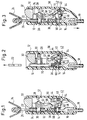
- a load-bearing housing 10 of the lock is surrounded by a cover shell 12 made of plastic.
- the housing 10 is connected by a rivet 14 to a fitting part 16, in which an anchoring cable 18 for pressing the lock to a vehicle seat or on the vehicle floor is pressed.
- the load-bearing housing 10 is formed from a generally U-shaped metal plate.
- An insertion path 20 for a tongue 22 of the seat belt system is formed between the two legs of the housing 10.
- the webbing 24 is through one Slot 26 of the tongue 22 out.
- a bolt 30 loaded by a compression spring 28 is displaceably guided transversely to the insertion path 20. In its position shown in FIG. 1, it crosses aligned openings of the housing 10 and the tongue 22. Between the inside of the cover shell 12 and the housing 10, a release button 32 is slidably guided. This release button 32 is provided with a recess for the passage of the bolt 30. The release button 32 is preloaded by a compression spring 36 into its unactuated position shown in FIG. 1.
- a U-shaped bearing bracket 38 is fastened to the housing 10 at the same time as the fitting 16.
- a two-armed lever 42 is pivotally mounted between the two legs of the bearing bracket 38 by means of a cylindrical hub 40.
- the two arms 44, 46 of the two-armed lever 42 are made in one piece with the hub 40 and project from it in a V-shape.
- the cylindrical hub 40 is provided with a coaxial bearing bore 48 for a bearing pin 50, which is fastened in the legs of the bearing bracket 38.
- the two-armed lever 42 is preloaded into its rest position shown in FIG. 1 by two torsion springs 52, 54 which act independently of one another. In this rest position, the arm 44 comes to rest against an inwardly projecting projection 56 of the cover shell 12.
- the release button 32 is provided at its end located inside the cover shell 12 with a shoulder 58 which has a concavely curved stop surface 60.
- the arm 46 of the lever 42 projects into the rest position of the same (FIG. 1) into the movement path of the extension 58 of the release button 32.
- the release button 32 is actuated, it is shifted into the interior of the cover shell 12, as shown in FIG. 2, the projection 48 abutting the arm 46 of the two-armed lever 42 and countering the spring preload due to the torsion springs 52, 54 from its rest position panned.
- the release button 32 is provided immediately above the shoulder 58 with a wedge-shaped recess 62 into which the arm 44 of the lever 42 dips.
- the bearing bracket 38 and the cylindrical hub 40 ensure a mechanically highly stressable mounting of the two-armed lever 42.
- the buckle described is intended for seat belt systems which are provided with a back tensioning device, which shift the buckle in the direction indicated by an arrow in FIG. 3 towards the vehicle floor, ie downward. This direction corresponds to the actuation direction of the release button 32.
- a back tensioning device which shift the buckle in the direction indicated by an arrow in FIG. 3 towards the vehicle floor, ie downward.
- This direction corresponds to the actuation direction of the release button 32.
- the downward movement of the lock is suddenly stopped.
- an extremely high deceleration occurs at the end of the back tension stroke.
- the release button 32 strives to continue the downward movement. However, it can only perform a downward movement when the inertial forces acting on it are greater than the force with which the spring 36 acts on the release button in its rest position.
- the center of gravity of the two-armed lever 42 lies in the arm 46 and is designated by the letter S.
- the lever 42 is the center of gravity so that the lever is pivoted counterclockwise under the action of the inertia forces occurring at the end of the backstroke stroke.
- the pivoting of the lever 42 only begins when the forces generated by inertia overcome the spring preload by the torsion springs 52, 54.
- the torsion springs 52, 54 are dimensioned such that the lever 42 is pivoted from its rest position into the deflected position shown in FIG. 3, even before the release button 32 begins its downward movement, with a relatively small delay in the lock at the end of the backward movement.
- FIG. 6 and 7 show two design variants with regard to the spring loading of the two-armed lever 42.
- the torsion springs 52, 54 of the arrangement shown in FIG. 4 are provided by a coil spring 70, which also acts as a torsion spring, with two in the same plane extending arms 72, 74 replaced.
- the cylindrical part of the spring 70 is fastened to the circumference of the hub 40 of the lever 42 by means of a rivet 76, a screw or the like.
- the cylindrical part of the spring 70 is received in the interior of an arcuate shell 78 molded onto the hub 40, over the upper ends of which the arms 72, 74 of the spring 70 extend.
- These spring arms engage with their ends in associated cutouts 80, 82 in the legs of the bearing bracket 38. This arrangement ensures that the spring 70 is installed with the correct orientation.
- a straight spring wire 90 is used for spring loading of the lever 42.
- This spring wire 90 is held in the middle by two lugs 92 forming a slot and molded onto the hub 40.
- the ends of the spring wire 90 engage in the associated cutouts 80, 82 of the bearing bracket 38.
Landscapes
- Automotive Seat Belt Assembly (AREA)
- Buckles (AREA)
Priority Applications (5)
| Application Number | Priority Date | Filing Date | Title |
|---|---|---|---|
| ES90121893T ES2032369T3 (es) | 1990-11-15 | 1990-11-15 | Cerradura para sistemas de cinturon de seguridad en vehiculos. |
| DE59009070T DE59009070D1 (de) | 1990-11-15 | 1990-11-15 | Schloss für Sicherheitsgurtsysteme in Fahrzeugen. |
| EP90121893A EP0485656B1 (fr) | 1990-11-15 | 1990-11-15 | Fermeture pour ceinture de sécurité de véhicules automobiles |
| US07/790,375 US5213365A (en) | 1990-11-15 | 1991-11-12 | Inertially locking buckle for seat pretensioner |
| JP3299222A JPH0651007B2 (ja) | 1990-11-15 | 1991-11-14 | 自動車用安全ベルト装置のための錠 |
Applications Claiming Priority (1)
| Application Number | Priority Date | Filing Date | Title |
|---|---|---|---|
| EP90121893A EP0485656B1 (fr) | 1990-11-15 | 1990-11-15 | Fermeture pour ceinture de sécurité de véhicules automobiles |
Publications (2)
| Publication Number | Publication Date |
|---|---|
| EP0485656A1 true EP0485656A1 (fr) | 1992-05-20 |
| EP0485656B1 EP0485656B1 (fr) | 1995-05-10 |
Family
ID=8204720
Family Applications (1)
| Application Number | Title | Priority Date | Filing Date |
|---|---|---|---|
| EP90121893A Expired - Lifetime EP0485656B1 (fr) | 1990-11-15 | 1990-11-15 | Fermeture pour ceinture de sécurité de véhicules automobiles |
Country Status (5)
| Country | Link |
|---|---|
| US (1) | US5213365A (fr) |
| EP (1) | EP0485656B1 (fr) |
| JP (1) | JPH0651007B2 (fr) |
| DE (1) | DE59009070D1 (fr) |
| ES (1) | ES2032369T3 (fr) |
Cited By (6)
| Publication number | Priority date | Publication date | Assignee | Title |
|---|---|---|---|---|
| FR2687965A1 (fr) * | 1992-02-19 | 1993-09-03 | Takata Corp | Dispositif a boucle pour ceinture de securite. |
| EP0723747A3 (fr) * | 1995-01-26 | 1996-12-18 | Trw Repa Gmbh | Boucle pour ceinture de sécurité |
| EP0679348A3 (fr) * | 1994-04-28 | 1997-01-29 | Hs Tech & Design | Boucle de ceinture de sécurité. |
| EP0820708A3 (fr) * | 1996-07-26 | 1998-12-02 | TRW Occupant Restraint Systems GmbH | Boucle pour ceinture de sécurité |
| WO1999007243A1 (fr) * | 1997-08-04 | 1999-02-18 | Breed Automotive Technology, Inc. | Boucle pour ceinture de securite |
| EP1025774A3 (fr) * | 1999-02-04 | 2001-01-17 | Breed Automotive Technology, Inc. | Boucle de ceinture de sécurité |
Families Citing this family (21)
| Publication number | Priority date | Publication date | Assignee | Title |
|---|---|---|---|---|
| DE4215563A1 (de) * | 1992-05-12 | 1993-11-18 | Trw Repa Gmbh | Schloß für Fahrzeug-Sicherheitsgurtsysteme |
| DE4416301A1 (de) * | 1994-05-09 | 1995-11-16 | Trw Repa Gmbh | Verschluß für Sicherheitsgurte |
| GB9409246D0 (en) * | 1994-05-10 | 1994-06-29 | Alliedsignal Ltd | Buckle mechanism |
| GB2296284A (en) * | 1994-12-23 | 1996-06-26 | Europ Component Co Ltd | Seat belt buckle |
| US5496068A (en) * | 1995-01-20 | 1996-03-05 | Trw Vehicle Safety Systems Inc. | Inertia sensitive buckle for seat belt pretensioner system |
| US5522619A (en) * | 1995-02-01 | 1996-06-04 | Alliedsignal Inc. | End release seat belt buckle having an inertia-sensitive locking mechanism |
| FI107850B (fi) * | 1995-06-30 | 2001-10-15 | Nokia Mobile Phones Ltd | Kantoväline matkaviestimen kiinnityslaitetta varten |
| DE29613690U1 (de) * | 1996-08-07 | 1996-12-05 | Trw Occupant Restraint Systems Gmbh, 73551 Alfdorf | Gurtstrafferfester Verschluß für Sicherheitsgurte |
| US5742987A (en) * | 1996-09-11 | 1998-04-28 | Alliedsignal Inc. | Buckle for use with a pretensioner |
| GB2323885A (en) * | 1997-04-02 | 1998-10-07 | Alliedsignal Ltd | Buckle with counterbalance mass |
| US5881439A (en) * | 1997-08-22 | 1999-03-16 | Trw Vehicle Safety Systems Inc. | Base and housing for seat belt buckle |
| JP3809007B2 (ja) * | 1998-03-25 | 2006-08-16 | タカタ株式会社 | バックル |
| JP4609922B2 (ja) * | 2003-10-24 | 2011-01-12 | タカタ株式会社 | バックルおよびこれを備えたシートベルト装置 |
| US7370393B2 (en) | 2004-09-20 | 2008-05-13 | Delphi Technologies, Inc. | Seat belt buckle for use with pretensioner |
| US7543363B2 (en) | 2005-05-26 | 2009-06-09 | Delphi Technologies, Inc. | Seat belt buckle for use with pretensioner |
| US7552518B2 (en) * | 2006-05-17 | 2009-06-30 | Delphi Technologies, Inc. | Seat belt buckle for use with pretensioner |
| ITTO20060492A1 (it) * | 2006-07-04 | 2008-01-05 | Novarace S R L | Dispositivo di chiusura per cinture di ritenuta, particolarmente per seggiolini di sicurezza automobilistici per bambini |
| WO2008022159A2 (fr) * | 2006-08-15 | 2008-02-21 | Delphi Technologies, Inc. | Boucle de ceinture de sécurité destinée à être utilisée avec un pré-tendeur |
| JP5688256B2 (ja) * | 2009-10-28 | 2015-03-25 | 芦森工業株式会社 | バックル装置 |
| US8516667B2 (en) * | 2010-05-19 | 2013-08-27 | GM Global Technology Operations LLC | Seat belt buckle |
| US9827947B2 (en) | 2016-02-10 | 2017-11-28 | Ford Global Technologies, Llc | Load limiting seat belt buckle assemblies |
Citations (6)
| Publication number | Priority date | Publication date | Assignee | Title |
|---|---|---|---|---|
| DE3021796A1 (de) * | 1980-06-11 | 1981-12-24 | Repa Feinstanzwerk Gmbh, 7071 Alfdorf | Gurtschloss fuer einen sicherheitsgurt |
| EP0212507A2 (fr) * | 1985-08-17 | 1987-03-04 | Autoflug Gmbh & Co Fahrzeugtechnik | Boucle de verrouillage pour ceinture de sécurité |
| DE3537465A1 (de) * | 1985-10-22 | 1987-04-23 | Autoflug Gmbh | Sicherheitsgurtverschluss |
| EP0364970A2 (fr) * | 1988-10-19 | 1990-04-25 | Autoliv Development Ab | Boucle pour un système de ceinture de sécurité destiné à un véhicule à moteur |
| EP0368277A1 (fr) * | 1988-11-08 | 1990-05-16 | General Engineering (Netherlands) B.V. | Boucle de ceinture de sécurité |
| DE3842453A1 (de) * | 1988-12-16 | 1990-06-21 | Autoliv Kolb Gmbh & Co | Schloss fuer ein kraftfahrzeug-sicherheitsgurtsystem |
Family Cites Families (6)
| Publication number | Priority date | Publication date | Assignee | Title |
|---|---|---|---|---|
| GB1589059A (en) * | 1978-05-12 | 1981-05-07 | Securon Ag | Buckle for safety belts and seat belts |
| GB2202264B (en) * | 1987-02-10 | 1991-04-24 | Autoliv Dev | Improvements in or relating to a safety belt buckle |
| DE3833483A1 (de) * | 1988-10-01 | 1990-04-05 | Autoflug Gmbh | Gurtschloss mit massenausgleich |
| US5054171A (en) * | 1989-06-14 | 1991-10-08 | Kabushiki Kaisha Tokai-Rika-Denki-Seisakusho | Buckle device |
| DE3929114A1 (de) * | 1989-09-01 | 1991-03-07 | Trw Repa Gmbh | Gurtschloss fuer ein sicherheitsgurtsystem, das mit einer rueckstrammeinrichtung versehen ist |
| DE4009272A1 (de) * | 1990-03-22 | 1991-09-26 | Trw Repa Gmbh | Gurtschloss fuer ein sicherheitsgurtsystem, das mit einer rueckstrammeinrichtung versehen ist |
-
1990
- 1990-11-15 ES ES90121893T patent/ES2032369T3/es not_active Expired - Lifetime
- 1990-11-15 DE DE59009070T patent/DE59009070D1/de not_active Expired - Fee Related
- 1990-11-15 EP EP90121893A patent/EP0485656B1/fr not_active Expired - Lifetime
-
1991
- 1991-11-12 US US07/790,375 patent/US5213365A/en not_active Expired - Fee Related
- 1991-11-14 JP JP3299222A patent/JPH0651007B2/ja not_active Expired - Lifetime
Patent Citations (6)
| Publication number | Priority date | Publication date | Assignee | Title |
|---|---|---|---|---|
| DE3021796A1 (de) * | 1980-06-11 | 1981-12-24 | Repa Feinstanzwerk Gmbh, 7071 Alfdorf | Gurtschloss fuer einen sicherheitsgurt |
| EP0212507A2 (fr) * | 1985-08-17 | 1987-03-04 | Autoflug Gmbh & Co Fahrzeugtechnik | Boucle de verrouillage pour ceinture de sécurité |
| DE3537465A1 (de) * | 1985-10-22 | 1987-04-23 | Autoflug Gmbh | Sicherheitsgurtverschluss |
| EP0364970A2 (fr) * | 1988-10-19 | 1990-04-25 | Autoliv Development Ab | Boucle pour un système de ceinture de sécurité destiné à un véhicule à moteur |
| EP0368277A1 (fr) * | 1988-11-08 | 1990-05-16 | General Engineering (Netherlands) B.V. | Boucle de ceinture de sécurité |
| DE3842453A1 (de) * | 1988-12-16 | 1990-06-21 | Autoliv Kolb Gmbh & Co | Schloss fuer ein kraftfahrzeug-sicherheitsgurtsystem |
Cited By (8)
| Publication number | Priority date | Publication date | Assignee | Title |
|---|---|---|---|---|
| FR2687965A1 (fr) * | 1992-02-19 | 1993-09-03 | Takata Corp | Dispositif a boucle pour ceinture de securite. |
| EP0679348A3 (fr) * | 1994-04-28 | 1997-01-29 | Hs Tech & Design | Boucle de ceinture de sécurité. |
| EP0723747A3 (fr) * | 1995-01-26 | 1996-12-18 | Trw Repa Gmbh | Boucle pour ceinture de sécurité |
| EP0820708A3 (fr) * | 1996-07-26 | 1998-12-02 | TRW Occupant Restraint Systems GmbH | Boucle pour ceinture de sécurité |
| WO1999007243A1 (fr) * | 1997-08-04 | 1999-02-18 | Breed Automotive Technology, Inc. | Boucle pour ceinture de securite |
| US6363591B1 (en) * | 1997-08-04 | 2002-04-02 | Breed Automotive Technology, Inc. | Safety belt buckle |
| EP1025774A3 (fr) * | 1999-02-04 | 2001-01-17 | Breed Automotive Technology, Inc. | Boucle de ceinture de sécurité |
| US6266855B1 (en) | 1999-02-04 | 2001-07-31 | Breed Automotive Technology, Inc. | Seat belt buckle |
Also Published As
| Publication number | Publication date |
|---|---|
| ES2032369T3 (es) | 1995-09-16 |
| JPH04266706A (ja) | 1992-09-22 |
| EP0485656B1 (fr) | 1995-05-10 |
| ES2032369T1 (es) | 1993-02-16 |
| JPH0651007B2 (ja) | 1994-07-06 |
| DE59009070D1 (de) | 1995-06-14 |
| US5213365A (en) | 1993-05-25 |
Similar Documents
| Publication | Publication Date | Title |
|---|---|---|
| EP0485656B1 (fr) | Fermeture pour ceinture de sécurité de véhicules automobiles | |
| DE69120749T2 (de) | Verriegelungsvorrichtung zur Verwendung in einem Fahrzeug | |
| EP0415418B1 (fr) | Boucle pour un système de ceinture de sécurité avec dispositif tendeur | |
| EP0568996B1 (fr) | Entraînement linéaire pour tendeur de ceinture de sécurité | |
| EP0300469A1 (fr) | Tendeur pour ceinture de sécurité | |
| EP0489950B1 (fr) | Fermeture pour ceinture de sécurité de véhicules automobiles | |
| DE68903326T2 (de) | Schloss fuer sicherheitsgurt. | |
| EP0447762B1 (fr) | Boucle de ceinture de sécurité pourvue d'un dispositif de tension | |
| EP0499665B1 (fr) | Dispositif pré-tendeur dans un système de ceinture de sécurité pour véhicules | |
| EP0721304B1 (fr) | Systeme de verrouillage pour ceinture de securite | |
| EP0569886B1 (fr) | Fermeture pour ceintures de sécurité de véhicules | |
| DE19502416A1 (de) | Verschluß für Sicherheitsgurte | |
| EP0528064A1 (fr) | Mécanisme de déclenchement pour un tendeur de ceinture | |
| EP0504657B2 (fr) | Fermeture pour ceintures de sécurité de véhicules | |
| WO2023285456A1 (fr) | Module pour un enrouleur de ceinture et enrouleur de ceinture | |
| DE4416138C2 (de) | Verschluß für Sicherheitsgurte | |
| DE69706053T2 (de) | Sitzgurtverschluss | |
| DE3006151C2 (fr) | ||
| DE9305221U1 (de) | Gurtstraffer für Fahrzeugsicherheitsgurte | |
| DE10041783B4 (de) | Verschluß, insbesondere Gurtschloß | |
| DE10041773B4 (de) | Gurtschloß | |
| EP0943507B1 (fr) | Rétracteur de sangle pour un système de ceinture de sécurité de véhicule | |
| EP0679348B1 (fr) | Boucle de ceinture de sécurité | |
| EP0514581B1 (fr) | Tendeur de ceinture de sécurité pour véhicules | |
| DE4027684C2 (de) | Gurtschloß für ein Sicherheitsgurtsystem, das mit einer Rückstrammeinrichtung versehen ist |
Legal Events
| Date | Code | Title | Description |
|---|---|---|---|
| PUAI | Public reference made under article 153(3) epc to a published international application that has entered the european phase |
Free format text: ORIGINAL CODE: 0009012 |
|
| AK | Designated contracting states |
Kind code of ref document: A1 Designated state(s): DE ES FR GB IT SE |
|
| EL | Fr: translation of claims filed | ||
| GBC | Gb: translation of claims filed (gb section 78(7)/1977) | ||
| 17P | Request for examination filed |
Effective date: 19920902 |
|
| ITCL | It: translation for ep claims filed |
Representative=s name: DR. ING. A. RACHELI & C. |
|
| 17Q | First examination report despatched |
Effective date: 19941021 |
|
| GRAA | (expected) grant |
Free format text: ORIGINAL CODE: 0009210 |
|
| AK | Designated contracting states |
Kind code of ref document: B1 Designated state(s): DE ES FR GB IT SE |
|
| REF | Corresponds to: |
Ref document number: 59009070 Country of ref document: DE Date of ref document: 19950614 |
|
| GBT | Gb: translation of ep patent filed (gb section 77(6)(a)/1977) |
Effective date: 19950519 |
|
| ITF | It: translation for a ep patent filed | ||
| ET | Fr: translation filed | ||
| REG | Reference to a national code |
Ref country code: ES Ref legal event code: FG2A Ref document number: 2032369 Country of ref document: ES Kind code of ref document: T3 |
|
| RAP2 | Party data changed (patent owner data changed or rights of a patent transferred) |
Owner name: TRW OCCUPANT RESTRAINT SYSTEMS GMBH |
|
| PLBE | No opposition filed within time limit |
Free format text: ORIGINAL CODE: 0009261 |
|
| STAA | Information on the status of an ep patent application or granted ep patent |
Free format text: STATUS: NO OPPOSITION FILED WITHIN TIME LIMIT |
|
| 26N | No opposition filed | ||
| PGFP | Annual fee paid to national office [announced via postgrant information from national office to epo] |
Ref country code: SE Payment date: 19971016 Year of fee payment: 8 |
|
| PGFP | Annual fee paid to national office [announced via postgrant information from national office to epo] |
Ref country code: GB Payment date: 19971106 Year of fee payment: 8 |
|
| PG25 | Lapsed in a contracting state [announced via postgrant information from national office to epo] |
Ref country code: GB Free format text: LAPSE BECAUSE OF NON-PAYMENT OF DUE FEES Effective date: 19981115 |
|
| PG25 | Lapsed in a contracting state [announced via postgrant information from national office to epo] |
Ref country code: SE Free format text: LAPSE BECAUSE OF NON-PAYMENT OF DUE FEES Effective date: 19981116 |
|
| GBPC | Gb: european patent ceased through non-payment of renewal fee |
Effective date: 19981115 |
|
| EUG | Se: european patent has lapsed |
Ref document number: 90121893.3 |
|
| PGFP | Annual fee paid to national office [announced via postgrant information from national office to epo] |
Ref country code: FR Payment date: 19991103 Year of fee payment: 10 |
|
| PGFP | Annual fee paid to national office [announced via postgrant information from national office to epo] |
Ref country code: ES Payment date: 19991117 Year of fee payment: 10 |
|
| PG25 | Lapsed in a contracting state [announced via postgrant information from national office to epo] |
Ref country code: ES Free format text: LAPSE BECAUSE OF NON-PAYMENT OF DUE FEES Effective date: 20001116 |
|
| PG25 | Lapsed in a contracting state [announced via postgrant information from national office to epo] |
Ref country code: FR Free format text: LAPSE BECAUSE OF NON-PAYMENT OF DUE FEES Effective date: 20010731 |
|
| REG | Reference to a national code |
Ref country code: FR Ref legal event code: ST |
|
| PGFP | Annual fee paid to national office [announced via postgrant information from national office to epo] |
Ref country code: DE Payment date: 20021127 Year of fee payment: 13 |
|
| REG | Reference to a national code |
Ref country code: ES Ref legal event code: FD2A Effective date: 20011214 |
|
| PG25 | Lapsed in a contracting state [announced via postgrant information from national office to epo] |
Ref country code: DE Free format text: LAPSE BECAUSE OF NON-PAYMENT OF DUE FEES Effective date: 20040602 |
|
| PG25 | Lapsed in a contracting state [announced via postgrant information from national office to epo] |
Ref country code: IT Free format text: LAPSE BECAUSE OF NON-PAYMENT OF DUE FEES;WARNING: LAPSES OF ITALIAN PATENTS WITH EFFECTIVE DATE BEFORE 2007 MAY HAVE OCCURRED AT ANY TIME BEFORE 2007. THE CORRECT EFFECTIVE DATE MAY BE DIFFERENT FROM THE ONE RECORDED. Effective date: 20051115 |