EP0485724B1 - Kippvorrichtung für Fahrerhäuser an Lastkraftwagen - Google Patents
Kippvorrichtung für Fahrerhäuser an Lastkraftwagen Download PDFInfo
- Publication number
- EP0485724B1 EP0485724B1 EP91116613A EP91116613A EP0485724B1 EP 0485724 B1 EP0485724 B1 EP 0485724B1 EP 91116613 A EP91116613 A EP 91116613A EP 91116613 A EP91116613 A EP 91116613A EP 0485724 B1 EP0485724 B1 EP 0485724B1
- Authority
- EP
- European Patent Office
- Prior art keywords
- cab
- driver
- piston drive
- rollers
- piston
- Prior art date
- Legal status (The legal status is an assumption and is not a legal conclusion. Google has not performed a legal analysis and makes no representation as to the accuracy of the status listed.)
- Expired - Lifetime
Links
Images

Classifications
-
- B—PERFORMING OPERATIONS; TRANSPORTING
- B62—LAND VEHICLES FOR TRAVELLING OTHERWISE THAN ON RAILS
- B62D—MOTOR VEHICLES; TRAILERS
- B62D33/00—Superstructures for load-carrying vehicles
- B62D33/06—Drivers' cabs
- B62D33/063—Drivers' cabs movable from one position into at least one other position, e.g. tiltable, pivotable about a vertical axis, displaceable from one side of the vehicle to the other
- B62D33/067—Drivers' cabs movable from one position into at least one other position, e.g. tiltable, pivotable about a vertical axis, displaceable from one side of the vehicle to the other tiltable
- B62D33/07—Drivers' cabs movable from one position into at least one other position, e.g. tiltable, pivotable about a vertical axis, displaceable from one side of the vehicle to the other tiltable characterised by the device for locking the cab in the tilted or in the driving position
Definitions
- the invention relates to a tilting device for cabs of trucks with a fluidic piston drive articulated on the one hand on the chassis and on the other hand on the driver's cab and a pawl catch which is arranged between the driver's cab and the piston drive and is effective in the driver's tilted position.
- a tilting device for truck cabs is known from DE-C-22 03 452.
- the tilting device has a latching element, the longitudinal axis of which is larger than the wide axis and which is fixedly attached to the driver's cab by means of a bolt.
- the latching element is guided in an elongated hole on the piston of the piston drive, so that the vertical spring movements of the driver's cab can be carried out without hindrance.
- the locking element is pivoted in the setting of the elongated hole part in such a way that the driver's cab can no longer make a forward falling movement when the tipping point is exceeded.
- the invention has for its object to improve the generic tilting device in terms of its life.
- the invention is shown in one embodiment.
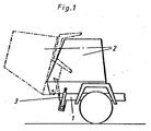
- FIG. 1 shows the front part of a truck with a chassis 1 and a cab 2 mounted thereon, which is shown in its ready to drive and in its tilted position.
- FIGS. 2-5 show the individual elements of the tilting device as well as the end and intermediate positions.
- a detent receiving element 8 is fixedly arranged on the piston 4 of the fluidic piston drive 3.
- the catch receiving element 8 has an elongated hole 9 with in the lower region on the elongated longitudinal sides 10 and 10 'arranged catches 11 and 11', which are offset from one another, are arranged.
- the detents 11 and 11 ' have a detent curve 12, which is composed of the individual curve sections 13 and 14.
- the detents 11 and 11 ' are arranged mirrored in 180 ° reversal.
- a latching element 5 is attached in a rotationally fixed manner to the driver's cab in the lower region thereof.
- the locking element has a longitudinal axis that is larger than its transverse axis.
- diametrically opposite rollers 6 At the locking element 5 are arranged at a distance from the longitudinal and transverse axes, diametrically opposite rollers 6, the circumference of which overlaps the contour of the locking element 5 and which rest on the elongated longitudinal sides 10, 10 '. 2, the cab can bounce downwards as well as upwards by rolling the rollers 6 on the long sides 10 and 10 '.
- the driver's cab is pressed off via the fluidic piston drive 3.
- Fig. 3 shows the end position of the translational movement of the piston drive.
- the latching curve 12 is composed of a first section 13 and a second section 14, which merge tangentially into one another.
- the first section 13 is generated by the radius that extends from the center of the locking element 5 to the circumference of the roller 6.
- the second detent section 14 is generated by the radius of the roller 6.
Landscapes
- Engineering & Computer Science (AREA)
- Chemical & Material Sciences (AREA)
- Combustion & Propulsion (AREA)
- Transportation (AREA)
- Mechanical Engineering (AREA)
- Actuator (AREA)
- Body Structure For Vehicles (AREA)
- Forklifts And Lifting Vehicles (AREA)
- Vehicle Body Suspensions (AREA)
Description
- Die Erfindung bezieht sich auf eine Kippvorrichtung für Fahrerhäuser von Lastkraftwagen mit einem einerseits am Fahrgestell und andererseits am Fahrerhaus angelenkten fluidischen Kolbenantrieb und einer zwischen Fahrerhaus und Kolbenantrieb angeordenten, in Kippstellung des Fahrerhauses wirksamen Klinkenverrasterung.
- Eine Kippvorrichtung für Lkw-Fahrerhäuser ist nach der DE-C-22 03 452 bekannt. Die Kippvorrichtung weist ein Rastelement auf, dessen Längsachse größer ist als die Breitachse und das mittels eines Bolzens fest am Fahrerhaus angebracht ist. Das Rastelement ist in einem am Kolben des Kolbenantriebes befindlichen Langloch geführt, so daß die vertikalen Federbewegungen des Fahrerhauses unbehindert ausgeführt werden können. Beim Kippen des Fahrerhauses wird das Rastelement in der Kulisse des Langlochteiles derart verschwenkt, daß das Fahrerhaus beim Überschreiten des Kippunktes keine Fallbewegung mehr nach vorne ausführen kann. Bei der Bewegung des Rastelementes im Langloch entsteht bei fahrbereitem Fahrerhaus Reibung aufgrund der Relativbewegung zwischen den Metallteilen, wie auch beim Kippen durch die kombinierte dreh- und translatorische Bewegung des Rastelementes in der Kulisse starke Reibungskräfte auftreten. Solcherart wird ein Biegemoment in die Kolbenstange des Kippzylinders eingeleitet, was zu Undichtigkeiten des Kippzylinders führen kann und somit dessen Lebendauer sehr begrenzt.
- Der Erfindung liegt die Aufgabe zugrunde, die gattungsgemäße Kippvorrichtung hinsichtlich ihrer Lebensdauer zu verbessern.
- Dies wird erfindungsgemäß durch die kennzeichnenden Merkmale des Anspruches 1 erreicht. Solcherart ergibt sich ein großer Vorteil gegenüber der bekannten gattungsgemäßen Vorrichtung, indem die Rollen sowohl in Gebrauchsstellung des Fahrerhauses als auch bei heruntergekipptem Fahrerhaus eine reine Rollbewegung im Langloch des Kolbenantriebes ausführen, wie auch beim Kippen, wenn die Rollen in der Kulisse des Langloches im Rastenaufnahmeelement abrollen. Dadurch wird verhindert, daß einerseits die Metallteile sich zu stark abnutzen und andererseits ein Biegemoment in die Kolbenstange eingeleitet wird.
- Die Erfindung ist in einem Ausführungsbeispiel dargestellt.
- Es zeigen:
- Fig. 1
- das Vorderteil eines Lastkraftwagens mit Fahrerhaus und Kippvorrichtung,
- Fig. 2
- einen Ausschnitt der Kippvorrichtung bei betriebsbereitem Fahrerhaus,
- Fig. 3 und Fig. 4
- Zwischenstellungen der Kippvorrichtung,
- Fig. 5
- Kippvorrichtung bei gekipptem Fahrerhaus.
- Fig. 1 zeigt den vorderen Teil eines Lkw's mit einem Fahrgestell 1 und einem darauf angebrachten Fahrerhaus 2, das in seiner fahrbereiten und in seiner gekippten Stellung gezeigt ist. Den Figuren 2 - 5 sind die Einzelelemente der Kippvorrichtung wie auch die End- und Zwischenpositionen zu entnehmen. Am Kolben 4 des fluidischen Kolbenantriebs 3 ist ein Rastenaufnahmeelement 8 fest angeordnet. Das Rastenaufnahmeelement 8 weist ein Langloch 9 mit im unteren Bereich an den Langlochlängsseiten 10 und 10′ angeordneten Rasten 11 und 11′ auf, die versetzt zueinander stehen, angeordnet sind. Die Rasten 11 und 11′ weisen eine Rastenkurve 12 auf, die sich aus den einzelnen Kurvenabschnitten 13 und 14 zusammensetzt. Die Rasten 11 und 11′ sind in 180° Umkehrung gespiegelt angeordnet. Am Fahrerhaus ist in dessen unteren Bereich ein Rastelement 5 drehfest angebracht. Das Rastelement hat eine Längsachse, die größer ist als seine Querachse. Am Rastelement 5 sind mit Abstand zur Längs- und zur Querachse, sich diametral gegenüberliegende Rollen 6 angeordnet, deren Umfang die Kontur des Rastelementes 5 übergreift und die an den Langloch-Längsseiten 10, 10′ anliegen. Nach Fig. 2 kann das Fahrerhaus nach unten wie auch nach oben durchfedern, indem die Rollen 6 an den Langlochlängsseiten 10 und 10′ abrollen. Zum Abkippen des Fahrerhauses wird das Fahrerhaus über den fluidischen Kolbentrieb 3 abgedrückt. Fig. 3 zeigt die Endstellung der translatorischen Bewegung des Kolbenantriebes. Fig. 4 zeigt die erste Phase der Schwenkbewegung, wobei die Rollen 6 in den ersten Abschnitt 13 der Rastenkurve 12 eingleiten. Aus Fig. 5 ist die Endstellung des fluidischen Kurbelantriebes und somit auch des abgekippten Fahrerhauses zu entnehmen. In dieser Endstellung kommen die Rollen 6 des Rastelementes 5 im zweiten Abschnitt 14 in der Rastenkurve 12 zur Anlage. Die Rastenkurve 12 setzt sich aus einem ersten Abschnitt 13 und einem zweiten Abschnitt 14 zusammen, die tangential ineinander übergehen. Der erste Abschnitt 13 wird durch den Radius erzeugt, der sich vom Mittelpunkt des Rastelementes 5 bis zum Umfang der Rolle 6 erstreckt. Der zweite Rastenabschnitt 14 wird durch den Radius der Rolle 6 erzeugt.
-
- 1
- Fahrgestell
- 2
- Fahrerhaus
- 3
- fluidischer Kolbenantrieb
- 4
- Kolben
- 5
- Rastelement
- 6
- Rollen
- 7
- -
- 8
- Rastenaufnahmeelement
- 9
- Langloch in 8
- 10, 10′
- Langlochlängsseiten
- 11, 11′
- Rasten
- 12
- Rastenkurve
- 13
- erster Abschnitt von 12
- 14
- zweiter Abschnitt von 12
Claims (1)
- Kippvorrichtung für Fahrerhäuser von Lastkraftwagen, mit einem einerseits am Fahrgestell und andererseits am Fahrerhaus angelenkten fluidischen Kolbenantrieb und einer zwischen Fahrerhaus und Kolbenantrieb angeordneten, in Kippstellung des Fahrerhauses wirksamen Klinkenverrasterung, dadurch gekennzeichnet, daß- am Fahrerhaus (2) ein ortfestes Rastelement (5) mit an ihm im Abstand zueinander und auf einer im spitzen Winkel zur Rastelement-Längsträgerachse befindlichen Achse angeordnete drehbare Rollen (6) vorgesehen ist, und- am Kolben (4) des Kolbentriebes (3) ein Rastenaufnahmeelement (8) mit einem Langloch (9) angeordnet ist, das in seinem unteren Bereich, auf beiden Langlochseiten (10, 10′) in der Tiefenerstreckung versetzt angeordnete kurvenförmige Rasten (11, 11′) aufweist und die Rastenkurve (12) in einem ersten Abschnitt (13) durch den vom Mittelpunkt des Rastelementes (5) bis zum Umfang der Rolle (6) sich erstreckenden Radius und in einem sich daran anschließenden zweiten Abschnitt (14) durch den Rollenradius erzeugt wird,- wobei bei betriebsbereitem Fahrerhaus (2) die Rollen (6), symmetrisch versetzt zur Langlochlängsachse, an den Langloch-Längsseiten (10, 10′) abrollbar anliegen, oder bei abgekipptem Fahrerhaus (2) die Rollen (6) über eine kombinierte translatorische Bewegung und Drehbewegung des Kolbenantriebes (3) zur Anlage in den Rasten (11,11′) kommen.
Applications Claiming Priority (2)
| Application Number | Priority Date | Filing Date | Title |
|---|---|---|---|
| DE4036554 | 1990-11-16 | ||
| DE4036554 | 1990-11-16 |
Publications (2)
| Publication Number | Publication Date |
|---|---|
| EP0485724A1 EP0485724A1 (de) | 1992-05-20 |
| EP0485724B1 true EP0485724B1 (de) | 1994-06-15 |
Family
ID=6418390
Family Applications (1)
| Application Number | Title | Priority Date | Filing Date |
|---|---|---|---|
| EP91116613A Expired - Lifetime EP0485724B1 (de) | 1990-11-16 | 1991-09-28 | Kippvorrichtung für Fahrerhäuser an Lastkraftwagen |
Country Status (3)
| Country | Link |
|---|---|
| EP (1) | EP0485724B1 (de) |
| AT (1) | ATE107248T1 (de) |
| DE (1) | DE59101941D1 (de) |
Families Citing this family (4)
| Publication number | Priority date | Publication date | Assignee | Title |
|---|---|---|---|---|
| AT403269B (de) * | 1993-05-14 | 1997-12-29 | Steyr Nutzfahrzeuge | Anlenkung eines kippzylinders am kippbaren fahrerhaus eines lastkraftwagens |
| NL1002247C2 (nl) * | 1996-02-05 | 1997-08-06 | Applied Power Inc | Voertuig met kantelbare cabine. |
| SE538236C2 (sv) | 2014-06-09 | 2016-04-12 | Scania Cv Ab | Ställdon, hyttippningsanordning, ett fordon samt en metod för att styra ett ställdon |
| DE102017123027A1 (de) * | 2017-10-04 | 2019-04-04 | Weber-Hydraulik Gmbh | Kippvorrichtung für das Fahrerhaus eines Lastkraftwagens |
Family Cites Families (1)
| Publication number | Priority date | Publication date | Assignee | Title |
|---|---|---|---|---|
| GB2080742A (en) * | 1980-07-30 | 1982-02-10 | Ford Motor Co | Support stay for vehicle tilt cab |
-
1991
- 1991-09-28 EP EP91116613A patent/EP0485724B1/de not_active Expired - Lifetime
- 1991-09-28 AT AT91116613T patent/ATE107248T1/de not_active IP Right Cessation
- 1991-09-28 DE DE59101941T patent/DE59101941D1/de not_active Expired - Fee Related
Also Published As
| Publication number | Publication date |
|---|---|
| EP0485724A1 (de) | 1992-05-20 |
| DE59101941D1 (de) | 1994-07-21 |
| ATE107248T1 (de) | 1994-07-15 |
Similar Documents
| Publication | Publication Date | Title |
|---|---|---|
| DE69833376T2 (de) | Verjüngte gebogene blattfeder für lkw-aufhängungen | |
| DE69431764T2 (de) | Lift-Achsen-Aufhängungssystem in Form eines Parallelogramms mit Steuerung der Achsen-Schwenkeinstellung | |
| DE69504667T2 (de) | Kupplungsvorrichtung zur kontrolle des winkelversetzes zwischen zwei wegtransporteinheiten die miteinander verbunden sind durch eine selbsttragende zwischeneinheit | |
| DE69018085T2 (de) | Einziehbare aufhängung. | |
| EP0631926A1 (de) | Raupenkettenfahrwerk | |
| DE2246542B2 (de) | Federung für Fahrzeuge | |
| DE69720887T2 (de) | Vorrichtung zur Stabilisierung | |
| DE2229834C3 (de) | Einzelradaufhängung für Kraftfahrzeuge | |
| DE3010381A1 (de) | Lenkbares drehgestell fuer einen eisenbahnwagen | |
| EP0370217A2 (de) | Aufhängung eines lenkbaren Fahrzeugrades | |
| DE1919350B2 (de) | Scheibenwischerarm | |
| AT399489B (de) | Kippvorrichtung zum entleeren von müllbehältern | |
| EP0485724A1 (de) | Kippvorrichtung für Fahrerhäuser an Lastkraftwagen | |
| DE3780570T2 (de) | Anordnung rohrfoermiger ladeflaechenrungen. | |
| DE2633683C2 (de) | Transportfahrzeug für Fertiggaragen und dergleichen | |
| DE942793C (de) | Schwenkvorrichtung, vorzugsweise fuer Fenster od. dgl. bei Kraftfahrzeugen | |
| AT410928B (de) | Hintere lagerung des kippbaren fahrerhauses eines frontlenker-lastkraftwagen | |
| DE60301411T2 (de) | Fahrzeug mit Bremse sowie Einzelradaufhängung | |
| DE2219575C3 (de) | Fahrerhaus für Nutzfahrzeuge | |
| DE4206342C2 (de) | Scheibenbremsgestänge für Schienenfahrzeuge mit querverschieblichem Radsatz | |
| DE102004042336A1 (de) | Flurförderzeug mit starr mit Lastverlagerungsvorrichtung verbundenem Zylinder | |
| EP0263283B1 (de) | Drehgestell und Schienenfahrzeug | |
| DE19529886C2 (de) | Schwenkbare Lenkvorrichtung | |
| DE8805243U1 (de) | Scharnier für die Bracke einer Ladefläche | |
| DE2628021C3 (de) | Balgverbindung zwischen dem Vorderwagen und dem Nachläufer eines Straßengelenkwagenzuges |
Legal Events
| Date | Code | Title | Description |
|---|---|---|---|
| PUAI | Public reference made under article 153(3) epc to a published international application that has entered the european phase |
Free format text: ORIGINAL CODE: 0009012 |
|
| AK | Designated contracting states |
Kind code of ref document: A1 Designated state(s): AT DE FR GB IT NL SE |
|
| 17P | Request for examination filed |
Effective date: 19920606 |
|
| 17Q | First examination report despatched |
Effective date: 19931119 |
|
| ITF | It: translation for a ep patent filed | ||
| GRAA | (expected) grant |
Free format text: ORIGINAL CODE: 0009210 |
|
| AK | Designated contracting states |
Kind code of ref document: B1 Designated state(s): AT DE FR GB IT NL SE |
|
| PG25 | Lapsed in a contracting state [announced via postgrant information from national office to epo] |
Ref country code: GB Effective date: 19940615 |
|
| REF | Corresponds to: |
Ref document number: 107248 Country of ref document: AT Date of ref document: 19940715 Kind code of ref document: T |
|
| ET | Fr: translation filed | ||
| REF | Corresponds to: |
Ref document number: 59101941 Country of ref document: DE Date of ref document: 19940721 |
|
| PGFP | Annual fee paid to national office [announced via postgrant information from national office to epo] |
Ref country code: AT Payment date: 19940912 Year of fee payment: 4 |
|
| GBV | Gb: ep patent (uk) treated as always having been void in accordance with gb section 77(7)/1977 [no translation filed] |
Effective date: 19940615 |
|
| EAL | Se: european patent in force in sweden |
Ref document number: 91116613.0 |
|
| PG25 | Lapsed in a contracting state [announced via postgrant information from national office to epo] |
Ref country code: NL Effective date: 19950401 |
|
| PLBE | No opposition filed within time limit |
Free format text: ORIGINAL CODE: 0009261 |
|
| STAA | Information on the status of an ep patent application or granted ep patent |
Free format text: STATUS: NO OPPOSITION FILED WITHIN TIME LIMIT |
|
| NLV4 | Nl: lapsed or anulled due to non-payment of the annual fee | ||
| 26N | No opposition filed | ||
| PG25 | Lapsed in a contracting state [announced via postgrant information from national office to epo] |
Ref country code: AT Effective date: 19950928 |
|
| PGFP | Annual fee paid to national office [announced via postgrant information from national office to epo] |
Ref country code: FR Payment date: 19980821 Year of fee payment: 8 |
|
| PGFP | Annual fee paid to national office [announced via postgrant information from national office to epo] |
Ref country code: SE Payment date: 19980824 Year of fee payment: 8 |
|
| PG25 | Lapsed in a contracting state [announced via postgrant information from national office to epo] |
Ref country code: SE Free format text: THE PATENT HAS BEEN ANNULLED BY A DECISION OF A NATIONAL AUTHORITY Effective date: 19990929 |
|
| EUG | Se: european patent has lapsed |
Ref document number: 91116613.0 |
|
| PG25 | Lapsed in a contracting state [announced via postgrant information from national office to epo] |
Ref country code: FR Free format text: LAPSE BECAUSE OF NON-PAYMENT OF DUE FEES Effective date: 20000531 |
|
| REG | Reference to a national code |
Ref country code: FR Ref legal event code: ST |
|
| PGFP | Annual fee paid to national office [announced via postgrant information from national office to epo] |
Ref country code: DE Payment date: 20010903 Year of fee payment: 11 |
|
| PG25 | Lapsed in a contracting state [announced via postgrant information from national office to epo] |
Ref country code: DE Free format text: LAPSE BECAUSE OF NON-PAYMENT OF DUE FEES Effective date: 20030401 |
|
| PG25 | Lapsed in a contracting state [announced via postgrant information from national office to epo] |
Ref country code: IT Free format text: LAPSE BECAUSE OF NON-PAYMENT OF DUE FEES Effective date: 20050928 |