EP0485742B1 - Diaphragme pour le rayonnement X primaire - Google Patents
Diaphragme pour le rayonnement X primaire Download PDFInfo
- Publication number
- EP0485742B1 EP0485742B1 EP91117317A EP91117317A EP0485742B1 EP 0485742 B1 EP0485742 B1 EP 0485742B1 EP 91117317 A EP91117317 A EP 91117317A EP 91117317 A EP91117317 A EP 91117317A EP 0485742 B1 EP0485742 B1 EP 0485742B1
- Authority
- EP
- European Patent Office
- Prior art keywords
- diaphragm
- group
- diaphragm plates
- pairs
- plates
- Prior art date
- Legal status (The legal status is an assumption and is not a legal conclusion. Google has not performed a legal analysis and makes no representation as to the accuracy of the status listed.)
- Expired - Lifetime
Links
Images

Classifications
-
- G—PHYSICS
- G21—NUCLEAR PHYSICS; NUCLEAR ENGINEERING
- G21K—HANDLING OF PARTICLES OR IONISING RADIATION NOT OTHERWISE PROVIDED FOR; IRRADIATION DEVICES; GAMMA RAY OR X-RAY MICROSCOPES
- G21K1/00—Arrangements for handling particles or ionising radiation, e.g. focusing or moderating
- G21K1/02—Arrangements for handling particles or ionising radiation, e.g. focusing or moderating using diaphragms, collimators
- G21K1/04—Arrangements for handling particles or ionising radiation, e.g. focusing or moderating using diaphragms, collimators using variable diaphragms, shutters, choppers
-
- A—HUMAN NECESSITIES
- A61—MEDICAL OR VETERINARY SCIENCE; HYGIENE
- A61B—DIAGNOSIS; SURGERY; IDENTIFICATION
- A61B6/00—Apparatus or devices for radiation diagnosis; Apparatus or devices for radiation diagnosis combined with radiation therapy equipment
- A61B6/06—Diaphragms
Definitions
- the invention relates to a primary radiation diaphragm for an X-ray tube with a first group of two diaphragm plate pairs arranged perpendicular to one another close to the focus of the X-ray tube and with a second group of two diaphragm plate pairs distant from the focus, the diaphragm plates of each pair of diaphragm plates using control means with respect to the longitudinal axis the diaphragm can be adjusted jointly and the first group of diaphragm plate pairs and the second group of diaphragm plate pairs are directed symmetrically against the longitudinal axis in the same way and can be adjusted by means of setting means in such a way that a radiation ray pyramid of the desired size is formed, the tip of which is in focus and the is limited by the first and the second group of aperture plate pairs.
- a primary beam aperture of this type is known from DE-OS 1 441 312.
- the diaphragm plates are adjusted by means of drive rollers and drive belts, which make the structure of the primary diaphragm relatively complicated.
- the belt drive because of the belt drive, a certain amount of play can occur during the displacement of the diaphragm plates, which has a negative effect on the accuracy when setting the primary beam diaphragm.
- the invention has for its object to provide a primary beam diaphragm of the type mentioned, which is simple in construction and yet has a high precision when adjusting the diaphragm plates.
- the setting means comprise a single first shaft that connects the control means of a pair of orifice plates in the first group with the control means of a pair of orifice plates in parallel in the second group, and another single shaft that connects the control means of the Diaphragm plate pair in the first group directly connects to the control means of the remaining diaphragm plate pair in the second group.
- the primary radiation diaphragm Because of the structure of the primary radiation diaphragm, it is also relatively simple to supplement it with further diaphragm plates which can be fitted between the first and the second group of diaphragm plate pairs.
- the control means of the further pairs of diaphragm plates are then connected to the shafts, which jointly control all pairs of diaphragm plates in this way.
- These additional diaphragm plates enable the X-rays to be masked out more effectively.
- a primary beam diaphragm according to the preamble of claim 7 is known from FR-A-635 489.
- the diaphragm plates of each pair of diaphragm plates are part of a parallelogram arm system and that the control means of the pair of diaphragm plates has a toothed segment and a gearwheel which engages in the toothed segment, the toothed segment being attached directly to an arm in the parallelogram arm system. This results in a very precise transmission of the movement of the gear wheel or tooth segment to the diaphragm plate pairs.
- the diaphragm plates of each pair of diaphragm plates have parts are of a parallelogram arm system and that the control means of the pair of diaphragm plates has a toothed segment and a gearwheel which engages in the toothed segment, the toothed segment itself forming an arm in the parallelogram arm system.
- the parallelogram arm system can be made relatively small, which also means that the aperture plates are correspondingly small.
- Such a pair of diaphragms is suitable for being brought close to the focus of the X-ray tube, since it can form the top of the radiation pyramid.
- a structurally simple embodiment of the invention is given in that the gears are firmly attached to the shafts.
- the first group of diaphragm plate pairs is smaller in size than the second group of diaphragm plate pairs, so that the primary beam diaphragm assumes the shape of a truncated cone.
- the primary beam diaphragm can be made relatively small and light, which is particularly advantageous when used in connection with a single tank for a mobile X-ray generator, since the single tank should be kept as small and light as possible.
- the teeth of the toothed segments are shaped in accordance with the angles of the shafts in relation to the longitudinal axis of the diaphragm. This ensures that the gears, which are attached to the shafts, are always straight regardless of the angles of the shafts.
- the invention also relates to a primary radiation diaphragm for an X-ray tube with a first group of two diaphragm plate pairs arranged perpendicular to one another, the diaphragm plates of each pair of diaphragm plates being parts of a parallelogram arm system and being adjustable in relation to the longitudinal axis of the diaphragm with the aid of a tooth segment, each of which Tooth segment is rotatable about an axis with the aid of a respective gear wheel.
- a primary beam aperture of this type is known from the Siemens data sheet "RUREK X-ray Collimator”.
- This diaphragm is a depth diaphragm with two diaphragm levels, in which the second diaphragm is an iris diaphragm. These aperture levels are set separately.
- the primary beam diaphragm comprises a second group of two diaphragm plate pairs arranged perpendicular to one another, which correspond to the first group of diaphragm plate pairs in terms of their structure and adjustment options and which are at a distance from the First group of diaphragm plate pairs are mounted seen in the longitudinal direction of the longitudinal axis, the first group of diaphragm plate pairs and the second group of diaphragm plate pairs being directed symmetrically against the longitudinal axis in the same way and wherein a gearwheel for setting a diaphragm plate pair in the first group and a corresponding gearwheel for setting a pair of orifice plates in the second group are mounted on a common rotatable shaft.
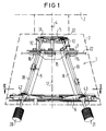
- FIG. 1 shows a primary radiation diaphragm 1 for an X-ray tube 2, which is mounted in a housing 3.
- the diaphragm 1 is a depth diaphragm with two diaphragm planes with a first group of two diaphragm plate pairs arranged perpendicular to one another, which are attached close to the focus 4 of the X-ray tube 1 and following an attachment 5.
- These aperture plate pairs are used in conjunction with FIG. 2 described in more detail.
- a second group of two mutually perpendicular diaphragm plate pairs, which are further away from the focus 4, are attached to a further attachment 6.
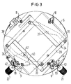
- the last-mentioned aperture plate pairs are used in conjunction with FIG. 3 described in more detail. From FIG.
- the attachment 5 with the first group of aperture plate pairs is smaller than the attachment 6 with the second group of aperture plate pairs, so that the primary beam aperture 1 takes the form of a truncated cone.
- a plate 7 is attached between plate 5 and 6, a plate 7 is attached. Spacer elements 8 to 11 are provided between this plate 7 and the attachment 6, only the spacer elements 8 and 9 being shown in the figure.
- Between the plate 7 and the attachment 5 further spacers 12 and 13 are attached.
- the plate 7 carries rollers 14, 15 and 16 with grooves in which a guide plate 22, which is fastened in the housing 3, is arranged. With this construction, the primary beam diaphragm can be rotated about its longitudinal axis 17.
- one aperture plate pair is attached to the upper side and the other aperture plate pair is attached to the lower side of the attachment 5.
- the further group of diaphragm plate pairs is distributed such that one pair of diaphragm plates is attached to the upper side and the other pair of diaphragm plates is attached to the lower side of the attachment 6.
- the pairs of diaphragm plates, which are attached to the upper side of the attachments 5, 6, are connected to one another by means of a shaft 18 via control means, which will be described later and which consist of toothed wheels and toothed segments.
- the pairs of diaphragm plates which are attached to the lower side of the attachments 5, 6, are also connected to one another by means of a shaft 19 via control means described later, which consist of toothed wheels and toothed segments.
- Each shaft 18, 19 has a rotary knob 20, 21. By turning the rotary knobs 20, 21, the shafts 18, 19 are rotated about their respective longitudinal axes, the diaphragm plate pairs which are connected to the respective shafts 18, 19 being able to be set into a desired position.
- aperture plate pairs 23, 24 are shown, which are attached to the top of the attachment 5.
- the diaphragm plates 23, 24 are parts of a parallelogram arm system, consisting of cross arms 25, 26, which can be rotated about an axis 27, 28, and of longitudinal arms 29, 30, which can be rotated about the cross arms 25, 26 are attached.
- One orifice plate 24 is attached to arm 29 and the other orifice plate 23 is attached to arm 30.
- the cross arm 25 is a tooth segment.
- the toothed segment 25 can be rotated about the axis 27 with the aid of a toothed wheel 31 which is fastened to the shaft 18 and bears against the toothed segment 25.
- FIG. 3 shows that pair of diaphragm plates 33, 34 which is attached to the upper side of the attachment 6.
- the diaphragm plates 33, 34 are fastened to a parallelogram arm system with cross arms 35, 36, the cross arm 35 being rotatable about a shaft 37.
- the parallelogram arm system also has longitudinal arms 38, 39 which are rotatable about the transverse arms 35, 36.
- the aperture plate 33 is attached to the arm 38 and the aperture plate 34 to the arm 39.
- a toothed segment 40 is attached directly to the cross arm 36 and is arranged to be rotatable about an axis 41.
- the toothed segment 40 and thus also the arm 36 can now be around the Axis 41 with the help of a gear 40 which is fixed to the shaft 18 and engages in the toothed segment, are rotated.
- the diaphragm plates 33, 34 are shifted against one another into a desired position. That pair of orifice plates, which is mounted perpendicular to the last-mentioned orifice plate pair 33, 34 on the lower side of the attachment 6 and therefore in FIG. 3 is not shown, the structure of the diaphragm plate pair 33, 34 does not differ, except that the toothed segment for controlling the diaphragm plates, not shown, is rotated with the aid of a gearwheel 43 fastened to the shaft 19. By turning the toothed segment, the diaphragm plates are moved towards each other in a desired position.
- the teeth of all tooth segments are shaped according to the angles of the shafts 18, 19 in relation to the longitudinal axis 17 of the diaphragm. In this way, only straight gears are used, which are attached to the shafts 18, 19.
- the translation between the gears or the tooth segments on the attachment 5 and the toothed wheels or the tooth segments on the attachment 6 is selected such that the aperture plate pairs on the attachment 6 are set in a simple manner can be, so that a pyramid of the desired size can be formed with an aperture.
Landscapes
- Health & Medical Sciences (AREA)
- Life Sciences & Earth Sciences (AREA)
- Engineering & Computer Science (AREA)
- Physics & Mathematics (AREA)
- Medical Informatics (AREA)
- High Energy & Nuclear Physics (AREA)
- Radiology & Medical Imaging (AREA)
- Animal Behavior & Ethology (AREA)
- Optics & Photonics (AREA)
- Pathology (AREA)
- Biophysics (AREA)
- Biomedical Technology (AREA)
- Heart & Thoracic Surgery (AREA)
- Molecular Biology (AREA)
- Surgery (AREA)
- Nuclear Medicine, Radiotherapy & Molecular Imaging (AREA)
- General Health & Medical Sciences (AREA)
- Public Health (AREA)
- Veterinary Medicine (AREA)
- Spectroscopy & Molecular Physics (AREA)
- General Engineering & Computer Science (AREA)
- Apparatus For Radiation Diagnosis (AREA)
- X-Ray Techniques (AREA)
Claims (12)
- Diaphragme du rayonnement primaire pour un tube à rayons X comportant un premier groupe formé de deux couples de plaques de diaphragme, disposées perpendiculairement l'une par rapport à l'autre à proximité du foyer du tube à rayons X, ainsi qu'un second groupe formé de deux couples de plaques de diaphragme éloignées du foyer et disposées perpendiculairement l'une à l'autre, et dans lequel les plaques de chaque couple de plaques de diaphragme peuvent être réglées en commun par rapport à l'axe longitudinal du diaphragme, à l'aide de moyens de commande et dans lequel le premier groupe de couples de plaques de diaphragme et le second groupe de couples de plaques de diaphragme sont dirigés symétriquement de la même manière par rapport à l'axe longitudinal et sont réglables à l'aide de moyens de réglage de telle sorte qu'il se forme une pyramide de rayonnement de taille désirée, dont la pointe est située au foyer et qui est limitée par les premier et second groupes de couples de plaques de diaphragme, caractérisé par le fait que les moyens de réglage comprennent un premier arbre individuel (18), qui relie directement le moyen de commande (25,31) d'un premier couple (23,24) de plaques de diaphragme du premier groupe au moyen de commande (40,42) d'un couple (33,34) de plaques de diaphragme, parallèles aux précédentes, du second groupe, et un autre arbre individuel (19), qui relie directement le moyen de commande (32) de l'autre couple de plaques de diaphragme du premier groupe au moyen de commande (43) de l'autre couple de plaques de diaphragme du second groupe.
- Diaphragme du rayonnement primaire suivant la revendication 1, caractérisé par le fait que les plaques (33, 34) de chaque couple de plaques de diaphragme font partie d'un système de bras en forme de parallélogramme et que le moyen de commande du couple (33,34) de plaques de diaphragme comporte un segment denté (40) et un pignon (42), qui engrène avec le segment denté (40), ce dernier étant monté directement sur un bras (36) du système de bras en forme de parallélogramme.
- Diaphragme du rayonnement primaire suivant la revendication 1, caractérisé par le fait que les plaques (23,24) de chaque couple de plaques de diaphragme font partie d'un système en forme de parallélogramme articulé ; et que les moyens de commande du couple (23,24) de plaques du diaphragme comportent un segment denté (25) et un pignon (31), qui engrène avec le segment denté (25), le segment denté (25) lui-même formant un bras du système en forme de parallélogramme articulé.
- Diaphragme du rayonnement primaire suivant l'une des revendications 1 à 3, caractérisé par le fait que les pignons (31,32,42,43) sont montés de façon fixe sur les arbres (18,19).
- Diaphragme du rayonnement primaire suivant l'une des revendications 1 à 4, caractérisé par le fait que le premier groupe de couples (23,24) de plaques de diaphragme a des dimensions inférieures à celle du second groupe de couples (33,34) de plaques de diaphragme de sorte que le diaphragme (1) du rayonnement primaire possède la forme d'un tronc de cône.
- Diaphragme du rayonnement primaire suivant l'une des revendications 1 à 5, caractérisé par le fait que les dents des segments dentés (25,40) sont conformées en fonction des angles des arbres (18,19) par rapport à l'axe longitudinal (17) du diaphragme (1).
- Diaphragme du rayonnement primaire pour un tube à rayons X comportant un premier groupe de couples de plaques de diaphragme, qui sont perpendiculaires l'une à l'autre, les plaques de chaque couple de plaques du diaphragme faisant partie d'un système en forme de parallélogramme articulé et étant réglables en commun, par rapport à l'axe longitudinal du diaphragme, à l'aide respectivement d'un segment denté, chaque segment denté pouvant tourner autour d'un axe sous l'action d'un pignon respectif, caractérisé par le fait que le diaphragme du rayonnement primaire comporte un second groupe de deux couples de plaques de diaphragme, perpendiculaires entre eux, qui correspond, du point de vue agencement et possibilités de réglage, au premier groupe de couples (23,24) de plaques de diaphragme et qui est disposé à distance du premier groupe de couples (23,24) de plaques de diaphragme, lorsqu'on regarde dans la direction longitudinale de l'axe longitudinal (17), le premier groupe de couples (23,24) de plaques de diaphragme et le second groupe de couples (33,34) de plaques de diaphragme étant dirigés de la même manière symétriquement par rapport à l'axe longitudinal (17), tandis qu'un pignon (31) pour le réglage d'un couple (23,24) de plaques de diaphragme du premier groupe et un pignon correspondant (42) pour le réglage d'un couple (33,34) de plaques de diaphragme du second groupe sont montés sur un arbre rotatif commun (18).
- Diaphragme du rayonnement primaire suivant la revendication 7, caractérisé par le fait que l'autre pignon (32) pour le premier groupe de couples de plaques de diaphragme et l'autre pignon (43) pour le second groupe de couples de plaques de diaphragme sont montés fixes sur un arbre rotatif commun (19).
- Diaphragme du rayonnement primaire suivant la revendication 7 ou 8, caractérisé par le fait que les segments dentés (40) sont disposés directement sur un bras (36) dans le système en forme de parallélogramme articulé.
- Diaphragme du rayonnement primaire suivant la revendication 7 ou 8, caractérisé par le fait que les segments dentés (25) forment un bras du système en forme de parallélogramme articulé.
- Diaphragme du rayonnement primaire suivant l'une des revendications 7 à 10, caractérisé par le fait que le premier groupe de couples (23,24) de plaques de diaphragme possède des dimensions inférieures à celles du second groupe de couples (33,34) de plaques de diaphragme, de sorte que le diaphragme (1) du rayonnement primaire possède la forme d'un tronc de cône.
- Diaphragme du rayonnement primaire suivant l'une des revendications 7 à 11, caractérisé par le fait que les dents des segments dentés (25,40) sont conformées en fonction des angles des arbres (18,19) par rapport à l'axe longitudinal (17) du diaphragme (1).
Applications Claiming Priority (2)
| Application Number | Priority Date | Filing Date | Title |
|---|---|---|---|
| SE9003638A SE9003638D0 (sv) | 1990-11-14 | 1990-11-14 | Primaerstraaleblaendare foer ett roentgenroer |
| SE9003638 | 1990-11-14 |
Publications (2)
| Publication Number | Publication Date |
|---|---|
| EP0485742A1 EP0485742A1 (fr) | 1992-05-20 |
| EP0485742B1 true EP0485742B1 (fr) | 1995-03-29 |
Family
ID=20380913
Family Applications (1)
| Application Number | Title | Priority Date | Filing Date |
|---|---|---|---|
| EP91117317A Expired - Lifetime EP0485742B1 (fr) | 1990-11-14 | 1991-10-10 | Diaphragme pour le rayonnement X primaire |
Country Status (5)
| Country | Link |
|---|---|
| US (1) | US5204892A (fr) |
| EP (1) | EP0485742B1 (fr) |
| JP (1) | JP3354950B2 (fr) |
| DE (1) | DE59105050D1 (fr) |
| SE (1) | SE9003638D0 (fr) |
Families Citing this family (16)
| Publication number | Priority date | Publication date | Assignee | Title |
|---|---|---|---|---|
| DE4229321C2 (de) * | 1992-09-02 | 1995-02-02 | Siemens Ag | Primärstrahlenblende für Strahlengeräte |
| SE9401904D0 (sv) * | 1994-06-02 | 1994-06-02 | Siemens Elema Ab | Röntgenundersökningsapparat |
| FR2764199B1 (fr) * | 1997-06-06 | 1999-07-16 | Arplay | Systeme de collimation pour la radiotherapie externe notamment dans la dmla |
| DE29710724U1 (de) * | 1997-06-19 | 1997-09-25 | Müller, Wulf, 22419 Hamburg | Blendensteuerung für medizinisches Röntgendiagnostikgerät mit drehbaren Bedienelementen zur Veränderung der Größe der Blendenöffnung |
| CN1603946A (zh) * | 2003-09-29 | 2005-04-06 | Ge医疗系统环球技术有限公司 | X射线光阑、x射线辐照器及x射线装置 |
| US7167542B2 (en) * | 2004-09-27 | 2007-01-23 | Siemens Medical Solutions Usa, Inc. | Motor arrangement and methods for a multi-leaf collimator |
| CN1786819B (zh) * | 2004-12-09 | 2011-08-10 | Ge医疗系统环球技术有限公司 | X射线光阑、x射线辐照器和x射线成像设备 |
| FR2864685B1 (fr) * | 2004-12-22 | 2008-03-14 | Ge Med Sys Global Tech Co Llc | Collimateur, emetteur de rayons x et appareil de radiographie |
| DE102005028208A1 (de) | 2005-06-17 | 2006-12-28 | Siemens Ag | Strahlenblende für eine Röntgeneinrichtung |
| US7783007B2 (en) * | 2006-07-27 | 2010-08-24 | Deutsches Krebsforschungszentrum Stiftung des öeffentlichen Rechts | Irradiation device and collimator |
| FI122093B (fi) * | 2007-03-19 | 2011-08-31 | Planmeca Oy | Röntgensädekeilan rajaaminen hammaslääketieteellisen kuvantamisen yhteydessä |
| US8093572B2 (en) * | 2007-06-29 | 2012-01-10 | Accuray Incorporated | Integrated variable-aperture collimator and fixed-aperture collimator |
| JP5358849B2 (ja) * | 2012-05-01 | 2013-12-04 | 株式会社アキュセラ | X線コリメータ |
| CN103462624B (zh) * | 2013-09-05 | 2016-07-06 | 中国科学院深圳先进技术研究院 | 一种x射线机限束器叶片驱动装置及x射线机限束器 |
| RU191752U1 (ru) * | 2019-02-05 | 2019-08-21 | Александр Григорьевич Таран | Устройство для диафрагмирования пучка рентгеновского излучения |
| CN116027564B (zh) * | 2023-01-05 | 2024-03-19 | 赛诺威盛科技(北京)股份有限公司 | 无级开缝准直器及ct扫描设备 |
Family Cites Families (8)
| Publication number | Priority date | Publication date | Assignee | Title |
|---|---|---|---|---|
| FR635489A (fr) * | 1927-06-03 | 1928-03-16 | Diaphragme à ouverture variable plus particulièrement utilisable en radiologie pour la limitation du champ de rayonnement | |
| US1909118A (en) * | 1928-05-29 | 1933-05-16 | Raab Leonhard | Diaphragm apparatus for x-ray tubes |
| US2959680A (en) * | 1956-03-28 | 1960-11-08 | Picker X Ray Corp | Adjustable collimator for radiation therapy |
| US3048700A (en) * | 1959-09-24 | 1962-08-07 | Westinghouse Electric Corp | X-ray shutter apparatus |
| DE1441312A1 (de) * | 1962-12-14 | 1968-10-24 | Siemens Ag | An einem Roentgenroehrengehaeuse angebrachte Primaerstrahlenblende |
| DE2035110A1 (en) * | 1970-07-15 | 1972-02-03 | Atowmjan A | Radio-medical irradiation source - in mounting with adjustable aperture |
| GB1565152A (en) * | 1976-11-27 | 1980-04-16 | Prontor Werk Gauthier Gmbh | Shieding device for protection of delicate organs during x-ray examination |
| DE3852009D1 (de) * | 1987-12-11 | 1994-12-08 | Varian International Ag | Therapiesimulator. |
-
1990
- 1990-11-14 SE SE9003638A patent/SE9003638D0/xx unknown
-
1991
- 1991-10-10 EP EP91117317A patent/EP0485742B1/fr not_active Expired - Lifetime
- 1991-10-10 DE DE59105050T patent/DE59105050D1/de not_active Expired - Fee Related
- 1991-11-06 US US07/789,239 patent/US5204892A/en not_active Expired - Lifetime
- 1991-11-08 JP JP32104391A patent/JP3354950B2/ja not_active Expired - Fee Related
Also Published As
| Publication number | Publication date |
|---|---|
| JPH04267041A (ja) | 1992-09-22 |
| EP0485742A1 (fr) | 1992-05-20 |
| SE9003638D0 (sv) | 1990-11-14 |
| DE59105050D1 (de) | 1995-05-04 |
| JP3354950B2 (ja) | 2002-12-09 |
| US5204892A (en) | 1993-04-20 |
Similar Documents
| Publication | Publication Date | Title |
|---|---|---|
| EP0485742A1 (fr) | Diaphragme pour le rayonnement X primaire | |
| EP0245768B1 (fr) | Collimateur de contour pour la radiothérapie | |
| DE2654778C2 (de) | Stereomikroskoptubus | |
| DE3718843C2 (fr) | ||
| DE4207006C2 (de) | Computertomograph | |
| DE3025186A1 (de) | Optisches system mit veraenderbarer betrachtungsrichtung, insbes. fuer endoskope | |
| WO2014072014A1 (fr) | Endoscope à optique orientable | |
| EP0236790B1 (fr) | Appareil de radiodiagnostic dentaire pour réaliser une tomographie panoramique de la machoîre d'un patient | |
| DE69530453T2 (de) | Kamera mit einer Zoomlinsenfassung | |
| EP0055209B1 (fr) | Dispositif pour faire tourner des faisceaux lumineux | |
| DE4232855A1 (de) | Kamera mit varioobjektiv und variosuchereinrichtung | |
| DE2633059C3 (de) | Röntgen-Primärstrahlenblende | |
| DE2634370A1 (de) | Vorrichtung zum bilden eines optischen gelenks | |
| DE2514401A1 (de) | Varioobjektivsystem | |
| DE4201169A1 (de) | Kipplinsensystem | |
| DE102022200997B4 (de) | Kollimator für eine Röntgenstrahlung | |
| DE2410744B2 (de) | Zoomobjektiv | |
| DE8711572U1 (de) | Primärstrahlenblende für Röntgendiagnostikgeräte | |
| EP0490107B1 (fr) | Table d'examen pour patient | |
| EP1129381A1 (fr) | Objectif a focale variable | |
| EP0184695A1 (fr) | Diaphragme pour rayonnement primaire dans un appareil d'examen radiologique | |
| EP0392385B1 (fr) | Appareil pour la correction de distortions de perspective | |
| DE2841611B2 (de) | Feldstecher | |
| DE19736815A1 (de) | Linseneinstellvorrichtung für Stereokamera | |
| DE3149723C2 (fr) |
Legal Events
| Date | Code | Title | Description |
|---|---|---|---|
| PUAI | Public reference made under article 153(3) epc to a published international application that has entered the european phase |
Free format text: ORIGINAL CODE: 0009012 |
|
| AK | Designated contracting states |
Kind code of ref document: A1 Designated state(s): DE FR GB IT SE |
|
| 17P | Request for examination filed |
Effective date: 19920625 |
|
| 17Q | First examination report despatched |
Effective date: 19940606 |
|
| GRAA | (expected) grant |
Free format text: ORIGINAL CODE: 0009210 |
|
| AK | Designated contracting states |
Kind code of ref document: B1 Designated state(s): DE FR GB IT SE |
|
| REF | Corresponds to: |
Ref document number: 59105050 Country of ref document: DE Date of ref document: 19950504 |
|
| ITF | It: translation for a ep patent filed | ||
| PG25 | Lapsed in a contracting state [announced via postgrant information from national office to epo] |
Ref country code: SE Effective date: 19950629 |
|
| GBT | Gb: translation of ep patent filed (gb section 77(6)(a)/1977) |
Effective date: 19950614 |
|
| ET | Fr: translation filed | ||
| PLBE | No opposition filed within time limit |
Free format text: ORIGINAL CODE: 0009261 |
|
| STAA | Information on the status of an ep patent application or granted ep patent |
Free format text: STATUS: NO OPPOSITION FILED WITHIN TIME LIMIT |
|
| 26N | No opposition filed | ||
| PGFP | Annual fee paid to national office [announced via postgrant information from national office to epo] |
Ref country code: GB Payment date: 19980909 Year of fee payment: 8 |
|
| PG25 | Lapsed in a contracting state [announced via postgrant information from national office to epo] |
Ref country code: GB Free format text: LAPSE BECAUSE OF NON-PAYMENT OF DUE FEES Effective date: 19991010 |
|
| GBPC | Gb: european patent ceased through non-payment of renewal fee |
Effective date: 19991010 |
|
| PGFP | Annual fee paid to national office [announced via postgrant information from national office to epo] |
Ref country code: FR Payment date: 20041029 Year of fee payment: 14 |
|
| PGFP | Annual fee paid to national office [announced via postgrant information from national office to epo] |
Ref country code: DE Payment date: 20041220 Year of fee payment: 14 |
|
| PG25 | Lapsed in a contracting state [announced via postgrant information from national office to epo] |
Ref country code: IT Free format text: LAPSE BECAUSE OF NON-PAYMENT OF DUE FEES;WARNING: LAPSES OF ITALIAN PATENTS WITH EFFECTIVE DATE BEFORE 2007 MAY HAVE OCCURRED AT ANY TIME BEFORE 2007. THE CORRECT EFFECTIVE DATE MAY BE DIFFERENT FROM THE ONE RECORDED. Effective date: 20051010 |
|
| PG25 | Lapsed in a contracting state [announced via postgrant information from national office to epo] |
Ref country code: DE Free format text: LAPSE BECAUSE OF NON-PAYMENT OF DUE FEES Effective date: 20060503 |
|
| PG25 | Lapsed in a contracting state [announced via postgrant information from national office to epo] |
Ref country code: FR Free format text: LAPSE BECAUSE OF NON-PAYMENT OF DUE FEES Effective date: 20060630 |
|
| REG | Reference to a national code |
Ref country code: FR Ref legal event code: ST Effective date: 20060630 |