EP0485752A1 - Rinförmiger Schraubenschlüssel mit 71/2 Grad Dreh-Spiel - Google Patents
Rinförmiger Schraubenschlüssel mit 71/2 Grad Dreh-Spiel Download PDFInfo
- Publication number
- EP0485752A1 EP0485752A1 EP91117611A EP91117611A EP0485752A1 EP 0485752 A1 EP0485752 A1 EP 0485752A1 EP 91117611 A EP91117611 A EP 91117611A EP 91117611 A EP91117611 A EP 91117611A EP 0485752 A1 EP0485752 A1 EP 0485752A1
- Authority
- EP
- European Patent Office
- Prior art keywords
- wrench
- socket
- degrees
- corner
- wrenching
- Prior art date
- Legal status (The legal status is an assumption and is not a legal conclusion. Google has not performed a legal analysis and makes no representation as to the accuracy of the status listed.)
- Withdrawn
Links
Images


Classifications
-
- B—PERFORMING OPERATIONS; TRANSPORTING
- B25—HAND TOOLS; PORTABLE POWER-DRIVEN TOOLS; MANIPULATORS
- B25B—TOOLS OR BENCH DEVICES NOT OTHERWISE PROVIDED FOR, FOR FASTENING, CONNECTING, DISENGAGING OR HOLDING
- B25B13/00—Spanners; Wrenches
-
- B—PERFORMING OPERATIONS; TRANSPORTING
- B25—HAND TOOLS; PORTABLE POWER-DRIVEN TOOLS; MANIPULATORS
- B25B—TOOLS OR BENCH DEVICES NOT OTHERWISE PROVIDED FOR, FOR FASTENING, CONNECTING, DISENGAGING OR HOLDING
- B25B13/00—Spanners; Wrenches
- B25B13/02—Spanners; Wrenches with rigid jaws
- B25B13/04—Spanners; Wrenches with rigid jaws of ring jaw type
Definitions
- the present invention relates to box wrenches and, in particular, to double-ended, reversible box wrenches for use with polygonal fasteners.
- a double-ended box wrench is one which has a handle shank interconnecting two wrenching heads, each of which has a polygonal socket opening having a plurality of corners and extending all the way through the head so as to present two wrenching faces, respectively, at the opposite ends of each opening.
- the two socket openings may be of the same or different sizes.
- the wrench is reversible if it can be flipped over to permit use of both wrenching faces of a head.
- the permitted swing angle is less than the angle between adjacent outwardly directed corners of the socket, e.g., 60° in the case of a hexagonal socket and 30° in the case of a double-hexagonal socket (wherein a double hexagon is two superimposed hexagons rotated 30° with respect to each other), then after the initial application through the permitted swing angle, the same wrenching head cannot be reapplied to the fastener in a different position to achieve further rotation in the same direction.
- An important feature of the invention is the provision of a double-ended box wrench which is reversible so that four different wrenching faces are available for application to a fastener.
- Another feature of the invention is the provision of a double-ended box wrench which permits repeated progressive rotation of a fastener, where the wrench can be rotated through only a very small angle during any one application.
- Still another feature of the invention is the provision of a double-ended, reversible box wrench which permits repeated progressive rotation of a polygonal fastener while moving the wrench through a swing angle of only 7-1/2°.
- a multiple-ended reversible box wrench for use with a polygonal fastener comprising: handle means including plural arms with each arm having a longitudinal axis and a free end, plural box wrenching heads equal in number to the arms and respectively integral with the free ends thereof, each of the heads having a polygonal socket opening extending therethrough, each of the socket openings being of the same size and having the same predetermined number of equiangularly spaced-apart outwardly directed corners with each of the corners having a corner axis which passes through the center of the socket opening, each of the socket openings being oriented so that one of its corner axes is inclined with respect to the longitudinal axis of the associated arm at a predetermined offset angle which is less than the angle between adjacent corner axes, one of the offset angles being A/4N and the difference between any two offset angles being an integer multiple of A/2N, where A is the angle between adjacent corner axes of the socket opening and N is the number of wrenching heads and
- FIGS. 1-3 there is illustrated a double-ended box wrench, generally designated by the numeral 10, in accordance with a first embodiment of the present invention.
- the wrench 10 is of unitary, one-piece construction and includes a generally flat handle shank 11 having two straight arms 12 and 13 joined at one end and each having a longitudinal axis. In the disclosed embodiment the arms 12 and 13 are aligned so as to have a common longitudinal axis 14, but that need not be the case.
- the wrench 10 is adapted for use with polygonal fasteners, such as a hexagonal fastener 15 (see FIGS.
- the socket openings 21 and 31 are the same size so that both are usable with the same fastener.
- the socket opening 21 has a center 22 and has 12 equiangularly-spaced apart and outwardly directed corners 23, each of which has a corner axis 24 extending through the apex of the corner and through the center 22 of the socket opening 21.
- Each of the corners 23 is defined by a pair of drive surfaces 25.
- the socket opening 21 extends completely through the wrenching head 20 providing two wrenching faces 26 and 27 for application to an associated fastener.
- the socket opening 31 has a center 32 and 12 equiangularly spaced-apart and outwardly directed corners 33, each having a corner axis 34, and each being defined by a pair of drive surfaces 35.
- the socket opening 31 also extends completely through the associated wrenching head 30, providing two wrenching faces 36 and 37.
- Each of the wrenching heads 20 and 30 is slightly thicker than the handle shank 11, with the drive surfaces 25 and 35 being disposed substantially perpendicular to a common medial plane 38 (FIG. 2), which is also the medial plane of the handle shank 11.
- the longitudinal axis 14 lies in the medial plane 38 and in a reference plane perpendicular thereto, which passes through the centers of the socket openings 21 and 31.
- the wrench 10 is reversible, i.e., any one of the wrenching faces 26, 27, 36 or 37 may be applied to an associated fastener without altering the inclination of the handle shank 11 with respect to the fastener axis.
- socket openings 21 and 31 are of identical size and shape, they are oriented differently with respect to the longitudinal axis 14 of the associated arms 12 and 13. More specifically, the socket opening 21 is oriented so that the corner 33 thereof closest to the longitudinal axis 14 is offset therefrom so that its corner axis 24 is disposed at an angle B with respect to the longitudinal axis 14.
- the socket opening 31, on the other hand, has its corner 23 nearest the longitudinal axis 14 offset therefrom so that its corner axis 34 defines an angle C with respect to the longitudinal axis 14.
- each of the angles B and C is less than the angle A between adjacent corners 23 or 33, the angle A being 30° in the case of a double-hexagonal socket opening.
- FIGS. 1 and 3 if B and C are different this arrangement results in four different wrenching faces, as viewed from the associated fastener, having offsets of +B, -B, +C and -C, respectively.
- the angle B is 11°-15', while the angle C is 3°-45'. It is a fundamental aspect of the invention that this arrangement provides a significant advantage, in that it permits repeated progressive rotation of an associated fastener 15 with the wrench 10 being rotated through a swing angle as small as 7°-30' during any one application. This is accomplished by sequential application of all four of the unique wrenching faces 26, 27, 36 and 37 which, for ease of illustration, have been respectively designated by the labels L1, L4, L2 and L3.
- FIGS. 4A-4E the wrench 10 is illustrated as being applied to a fastener 15, with the handle shank 11 being disposed between lateral obstructions 39 and 39a which limit the rotation of the wrench 10 during any one application to a swing angle of 7°-30'.
- the starting and ending positions of the handle shank 11 during such a 7-1/2° rotation are illustrated, respectively, by the solid and broken line positions of the handle shank 11 in FIG. 4A.
- the starting position of the fastener 15 is illustrated in FIG. 4A with the darkened corner 17A having its corner axis 18 oriented vertically, as illustrated by the broken-line vertical axis V.
- the socket openings 21 and 31 are so dimensioned that there is a slight rotational clearance or "play" between the drive surfaces 25 and 35 and the sides of the fastener 15 to assure ease of application of the wrench to the fastener.
- the wrench 10 must undergo a very slight rotation in order to bring the drive surfaces 25 into engagement with the fastener sides, as illustrated in FIG. 4A.
- the wrenching face L1 is applied to the fastener 15, this wrenching face presenting the socket opening 21 with an offset of 11-1/4° counterclockwise from the longitudinal axis 14 of the arm 12.
- the wrench 10 is rotated 7-1/2° counterclockwise it will rotate the fastener 15 through 7-1/2° to the position illustrated in FIG. 4B.
- the wrench 10 is then turned over or reversed and the wrenching face L4 is applied to the fastener 15. It can be seen that the offset angles are such that, when the handle shank 11 is moved as far left as possible against the obstruction 39, the socket opening 21 will just fit over the fastener 15.
- the fastener 15 will have been brought to the position illustrated in FIG. 4C.
- the wrench 10 is then switched end for end and the wrenching face L3 is applied to the fastener 15, the angles being such that this application is permitted if the wrench is moved as far as possible to the left against the obstruction 39.
- a further 7-1/2° counterclockwise rotation will bring the fastener to the position illustrated in FIG. 4D, at which point the wrench 10 is reversed and the wrenching face L2 is applied to the fastener.
- a further 7-1/2° rotation will bring the fastener to the position illustrated in FIG. 4E.
- the fastener 15 has been rotated 30° from the starting position of FIG. 4A.
- Wrenching face L1 can now again be applied to the fastener 15 and the sequence can be repeated as often as is necessary to rotate the fastener 15 the desired amount.
- a fastener cannot be rotated in the same direction by repeated applications of the same wrenching face if the permitted swing angle is less than the angle between the corner axes of adjacent corners of the socket opening, which angle is designated A in FIG. 1.
- the angle A is 30°.
- the face L1 or a face identical to it
- the present invention minimizes the swing angle which will accommodate repeated progressive rotation of a fastener. This is accomplished by offsetting the socket openings with respect to the longitudinal axes of the associated arms.
- One fundamental aspect of the invention is that, for any given wrench, it provides a number of unique wrenching faces which is greater than the number of wrenching heads, and it accomplishes this by providing, for any one wrenching head, two unique wrenching faces.
- This is achieved by orienting the polygonal socket opening so that the outwardly directed corner thereof nearest the longitudinal axis of the associated arm has a corner axis which is offset with respect to the arm axis by a predetermined angle which has a magnitude greater than zero and less than the angular distance between adjacent outwardly directed corners of the socket opening. More specifically, it will be noted that if the offset angle of a socket opening has a magnitude greater than zero, its corner axes will be inclined with respect to the longitudinal axis of the associated arm.
- the opposite wrenching faces of the wrenching head are different since, for one face the offset angle will be in a clockwise direction while, for the opposite face, the offset angle will be in a counterclockwise direction.
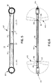
- the offset angle is zero (see FIG. 5), i.e., a corner of the socket opening has its corner axis aligned with the longitudinal axis of the associated arm, then the two opposing faces of that wrenching head will be identical so that, effectively, only one wrenching face is provided by that wrenching head.
- the number F of different wrenching faces provided by the wrench is given by the expression 2N - M, where N is the number of wrenching heads and M is the number of heads wherein the socket opening has an offset angle of zero degrees.
- A/F is the minimum swing angle necessary to ensure repeated progressive rotation of the fastener and, therefore, represents the lower limit of the swing angle permitted by environmental obstructions.
- the minimum swing angle, A/2N is 7-1/2°.
- FIG. 6 there is illustrated an alternative embodiment of the wrench of the present invention, generally designated by the numeral 40, having an elongated handle shank 41 provided at its opposite ends with projecting tongues 42.
- Wrenching heads 43 and 44 are coupled to the opposite ends of the handle shank 41, each of the wrenching head 43 and 44 having a clevis end 45 which straddles the associated tongue 42 and is pivotally coupled thereto as by a pivot pin 46.
- each of the wrenching heads 43 and 44 is pivotally movable, as indicated in FIG. 6, about the axis of the associated pivot pin 46 for changing the inclination of the wrenching head 43 with respect to the longitudinal axis of the handle shank 41.
- the wrench 40 permits the handle shank 41 and the user's hand to be inclined at various angles with respect to the fastener axis to clear adjacent obstructions. It will be appreciated that the wrench 40 may use any of the types of socket opening configurations described above to permit repeated progressive rotation of a fastener with a minimal swing angle, even with difficult fastener locations.
Landscapes
- Engineering & Computer Science (AREA)
- Mechanical Engineering (AREA)
- Details Of Spanners, Wrenches, And Screw Drivers And Accessories (AREA)
Applications Claiming Priority (2)
| Application Number | Priority Date | Filing Date | Title |
|---|---|---|---|
| US611733 | 1990-11-13 | ||
| US07/611,733 US5218891A (en) | 1990-11-13 | 1990-11-13 | Double-ended reversible box wrench with 71/2 degree swing clearance |
Publications (1)
| Publication Number | Publication Date |
|---|---|
| EP0485752A1 true EP0485752A1 (de) | 1992-05-20 |
Family
ID=24450213
Family Applications (1)
| Application Number | Title | Priority Date | Filing Date |
|---|---|---|---|
| EP91117611A Withdrawn EP0485752A1 (de) | 1990-11-13 | 1991-10-16 | Rinförmiger Schraubenschlüssel mit 71/2 Grad Dreh-Spiel |
Country Status (7)
| Country | Link |
|---|---|
| US (1) | US5218891A (de) |
| EP (1) | EP0485752A1 (de) |
| JP (1) | JPH04269176A (de) |
| KR (1) | KR920009513A (de) |
| AU (1) | AU8771291A (de) |
| CA (1) | CA2053142A1 (de) |
| MX (1) | MX9101920A (de) |
Cited By (1)
| Publication number | Priority date | Publication date | Assignee | Title |
|---|---|---|---|---|
| EP0589482A1 (de) * | 1992-09-24 | 1994-03-30 | UTENSILERIE ASSOCIATE S.p.A. | Ringschluessel |
Families Citing this family (21)
| Publication number | Priority date | Publication date | Assignee | Title |
|---|---|---|---|---|
| USD394793S (en) | 1996-01-19 | 1998-06-02 | Ma James W | Multi-purpose tool |
| US5685206A (en) * | 1996-01-19 | 1997-11-11 | Ma; James W. | Multi-purpose tool |
| JPH10187157A (ja) * | 1996-12-20 | 1998-07-14 | Kawai Musical Instr Mfg Co Ltd | 自動演奏装置 |
| US5865074A (en) * | 1997-03-19 | 1999-02-02 | Hsieh; Chih-Ching | Box end wrench with stop means to hold down the bolt or nut to be turned |
| US6301999B1 (en) | 2000-06-20 | 2001-10-16 | The Stanley Works | Ratchet wrench with force balanced pawl |
| USD441625S1 (en) | 2000-08-31 | 2001-05-08 | Ander Chen | Wrench |
| USD465707S1 (en) | 2001-07-18 | 2002-11-19 | Ander Chen | Wrench |
| TW509129U (en) | 2001-11-28 | 2002-11-01 | Hou-Fei Hu | Fastening device for tool |
| US6662687B2 (en) | 2002-04-10 | 2003-12-16 | The Stanley Works | Ratchet wrench with improved force distribution |
| US6666113B1 (en) * | 2002-04-22 | 2003-12-23 | Gabriel Bravo | Valve wrench |
| USD487681S1 (en) | 2003-04-01 | 2004-03-23 | Chih-Ching Hsien | Wrench |
| USD487682S1 (en) | 2003-06-12 | 2004-03-23 | Chih-Ching Hsien | Wrench |
| US7343836B1 (en) | 2005-03-01 | 2008-03-18 | Jess Ward | Bender wrench |
| US7353735B2 (en) * | 2005-06-02 | 2008-04-08 | The Stanley Works | Ratchet wrench |
| USD562655S1 (en) * | 2007-05-16 | 2008-02-26 | He-Nan Chen | Twisting socket |
| USD665640S1 (en) * | 2009-10-01 | 2012-08-21 | Taylor James W Jr | Wrench |
| US20110146462A1 (en) * | 2009-12-23 | 2011-06-23 | Watts Sr Bryan W | Watts magnetic wrench systems |
| US9925654B2 (en) * | 2012-08-15 | 2018-03-27 | Gary Dean Ragner | Folding multiwrenches |
| US9027446B1 (en) | 2013-01-16 | 2015-05-12 | Scientific Components Corporation | Wrench adaptor |
| JP6360689B2 (ja) * | 2014-03-06 | 2018-07-18 | 大和ハウス工業株式会社 | スパナ |
| DE202026000965U1 (de) | 2026-03-04 | 2026-04-30 | Tsan-Chang Lee | Ringschlüsselstruktur |
Citations (3)
| Publication number | Priority date | Publication date | Assignee | Title |
|---|---|---|---|---|
| DE396544C (de) * | 1922-11-14 | 1924-06-03 | Willy Blaufelder | Schraubenschluessel oder Schraubenzieher |
| GB1042403A (en) * | 1963-04-02 | 1966-09-14 | Jacob Lionel Davies | Improvements in or relating to spanners and the like |
| FR2563140A1 (fr) * | 1984-04-24 | 1985-10-25 | Facom | Cle a oeil perfectionnee |
Family Cites Families (9)
| Publication number | Priority date | Publication date | Assignee | Title |
|---|---|---|---|---|
| US493051A (en) * | 1893-03-07 | Walfrid a | ||
| US964067A (en) * | 1909-03-26 | 1910-07-12 | Andrew S Steen | Wrench. |
| US1261565A (en) * | 1918-01-26 | 1918-04-02 | Hugo F Leitner | Wrench. |
| US1643814A (en) * | 1926-05-11 | 1927-09-27 | John N Peterson | Socket wrench |
| US1764990A (en) * | 1929-05-09 | 1930-06-17 | Joseph B Schultz | Nonslipping wrench |
| US2951405A (en) * | 1957-12-09 | 1960-09-06 | Bahco Ab | Multiple grip wrench |
| FR2227093A1 (en) * | 1973-04-27 | 1974-11-22 | Wilmonda Manuf Outillage | Double open headed spanner for pipe couplings - series of flats on one head is rotated 30 degrees w.r.t. those on second head |
| GB1603848A (en) * | 1978-05-26 | 1981-12-02 | Motaproducts Automotive Ltd | Spanners |
| US4327611A (en) * | 1980-08-11 | 1982-05-04 | Catanese Salvatore S | Adjustable sleeve flex wrench |
-
1990
- 1990-11-13 US US07/611,733 patent/US5218891A/en not_active Expired - Fee Related
-
1991
- 1991-10-10 CA CA002053142A patent/CA2053142A1/en not_active Abandoned
- 1991-10-16 EP EP91117611A patent/EP0485752A1/de not_active Withdrawn
- 1991-11-05 MX MX9101920A patent/MX9101920A/es unknown
- 1991-11-08 AU AU87712/91A patent/AU8771291A/en not_active Abandoned
- 1991-11-12 KR KR1019910020056A patent/KR920009513A/ko not_active Withdrawn
- 1991-11-12 JP JP3295740A patent/JPH04269176A/ja active Pending
Patent Citations (3)
| Publication number | Priority date | Publication date | Assignee | Title |
|---|---|---|---|---|
| DE396544C (de) * | 1922-11-14 | 1924-06-03 | Willy Blaufelder | Schraubenschluessel oder Schraubenzieher |
| GB1042403A (en) * | 1963-04-02 | 1966-09-14 | Jacob Lionel Davies | Improvements in or relating to spanners and the like |
| FR2563140A1 (fr) * | 1984-04-24 | 1985-10-25 | Facom | Cle a oeil perfectionnee |
Cited By (1)
| Publication number | Priority date | Publication date | Assignee | Title |
|---|---|---|---|---|
| EP0589482A1 (de) * | 1992-09-24 | 1994-03-30 | UTENSILERIE ASSOCIATE S.p.A. | Ringschluessel |
Also Published As
| Publication number | Publication date |
|---|---|
| JPH04269176A (ja) | 1992-09-25 |
| US5218891A (en) | 1993-06-15 |
| KR920009513A (ko) | 1992-06-25 |
| MX9101920A (es) | 1992-07-08 |
| AU8771291A (en) | 1992-05-14 |
| CA2053142A1 (en) | 1992-05-14 |
Similar Documents
| Publication | Publication Date | Title |
|---|---|---|
| US5218891A (en) | Double-ended reversible box wrench with 71/2 degree swing clearance | |
| US5537897A (en) | Split socket with movable facets and drive assembly | |
| US4374479A (en) | Torque transfer device for wrench applications | |
| EP0740981B1 (de) | Einstückiger, in Form eines offenen Mauls geformter Schraubenschlüsselkopf mit gezahnten Backen | |
| US6112625A (en) | Extension bar for tool | |
| US5829327A (en) | Open-end ratchet wrench | |
| US4367664A (en) | Combination tool | |
| US5860339A (en) | Drive configuration with differential driving surfaces | |
| US5018412A (en) | Open-end ratchet wrench | |
| US5582082A (en) | Open-end wrench having self-contained ratcheting mechanism allowing one-way rotational driving of a hardware element | |
| US6092441A (en) | Multiple fitting | |
| US3931749A (en) | Reversible self-retaining ratcheting wrench | |
| US6805029B1 (en) | Extensible speed wrench crowfoot wrench head | |
| US6158309A (en) | Double-drive double-lock ratcheting wrench | |
| US5406868A (en) | Open end wrench | |
| CA1204006A (en) | Adjustable wrench | |
| US4827811A (en) | Tamper-resistant fastener and tool for operating same | |
| US4554847A (en) | Open end ratchet wrench | |
| US6223630B1 (en) | Open end ratchet wrench | |
| US5050464A (en) | Multi-surface wrench | |
| US4924736A (en) | Gripping screw drive bit | |
| EP0580177B1 (de) | Schraubenschlüssel für Schnellmontage | |
| US4593585A (en) | Adjustable wrench | |
| JPH0735026B2 (ja) | ラチエツトスパナ | |
| US7201086B2 (en) | Wrench with articulating head |
Legal Events
| Date | Code | Title | Description |
|---|---|---|---|
| PUAI | Public reference made under article 153(3) epc to a published international application that has entered the european phase |
Free format text: ORIGINAL CODE: 0009012 |
|
| AK | Designated contracting states |
Kind code of ref document: A1 Designated state(s): BE DE FR GB IT LU NL |
|
| STAA | Information on the status of an ep patent application or granted ep patent |
Free format text: STATUS: THE APPLICATION IS DEEMED TO BE WITHDRAWN |
|
| 18D | Application deemed to be withdrawn |
Effective date: 19921121 |