EP0485790A2 - Vorrichtung zum Trennen und Besäumen von Leiterplatten - Google Patents
Vorrichtung zum Trennen und Besäumen von Leiterplatten Download PDFInfo
- Publication number
- EP0485790A2 EP0485790A2 EP91118290A EP91118290A EP0485790A2 EP 0485790 A2 EP0485790 A2 EP 0485790A2 EP 91118290 A EP91118290 A EP 91118290A EP 91118290 A EP91118290 A EP 91118290A EP 0485790 A2 EP0485790 A2 EP 0485790A2
- Authority
- EP
- European Patent Office
- Prior art keywords
- circuit board
- circuit boards
- printed circuit
- saw blades
- cutting disc
- Prior art date
- Legal status (The legal status is an assumption and is not a legal conclusion. Google has not performed a legal analysis and makes no representation as to the accuracy of the status listed.)
- Granted
Links
- 238000007688 edging Methods 0.000 title abstract 2
- 238000005520 cutting process Methods 0.000 claims abstract description 22
- 229910003460 diamond Inorganic materials 0.000 claims abstract description 6
- 239000010432 diamond Substances 0.000 claims abstract description 6
- 238000000926 separation method Methods 0.000 claims abstract description 5
- 238000009966 trimming Methods 0.000 claims description 5
- 238000007654 immersion Methods 0.000 claims 1
- 238000000034 method Methods 0.000 abstract description 7
- 238000012545 processing Methods 0.000 description 6
- 229920003002 synthetic resin Polymers 0.000 description 4
- 239000000057 synthetic resin Substances 0.000 description 4
- 238000003801 milling Methods 0.000 description 2
- 230000036346 tooth eruption Effects 0.000 description 2
- 230000002411 adverse Effects 0.000 description 1
- 230000015572 biosynthetic process Effects 0.000 description 1
- 238000001816 cooling Methods 0.000 description 1
- 230000009969 flowable effect Effects 0.000 description 1
- 238000003754 machining Methods 0.000 description 1
- 238000004519 manufacturing process Methods 0.000 description 1
- 239000002245 particle Substances 0.000 description 1
- 230000002093 peripheral effect Effects 0.000 description 1
- 238000012805 post-processing Methods 0.000 description 1
- 238000007711 solidification Methods 0.000 description 1
- 230000008023 solidification Effects 0.000 description 1
Images


Classifications
-
- B—PERFORMING OPERATIONS; TRANSPORTING
- B23—MACHINE TOOLS; METAL-WORKING NOT OTHERWISE PROVIDED FOR
- B23D—PLANING; SLOTTING; SHEARING; BROACHING; SAWING; FILING; SCRAPING; LIKE OPERATIONS FOR WORKING METAL BY REMOVING MATERIAL, NOT OTHERWISE PROVIDED FOR
- B23D45/00—Sawing machines or sawing devices with circular saw blades or with friction saw discs
- B23D45/10—Sawing machines or sawing devices with circular saw blades or with friction saw discs with a plurality of circular saw blades
- B23D45/105—Sawing machines or sawing devices with circular saw blades or with friction saw discs with a plurality of circular saw blades operating within the same plane
-
- B—PERFORMING OPERATIONS; TRANSPORTING
- B27—WORKING OR PRESERVING WOOD OR SIMILAR MATERIAL; NAILING OR STAPLING MACHINES IN GENERAL
- B27B—SAWS FOR WOOD OR SIMILAR MATERIAL; COMPONENTS OR ACCESSORIES THEREFOR
- B27B33/00—Sawing tools for saw mills, sawing machines, or sawing devices
- B27B33/20—Edge trimming saw blades or tools combined with means to disintegrate waste
-
- H—ELECTRICITY
- H05—ELECTRIC TECHNIQUES NOT OTHERWISE PROVIDED FOR
- H05K—PRINTED CIRCUITS; CASINGS OR CONSTRUCTIONAL DETAILS OF ELECTRIC APPARATUS; MANUFACTURE OF ASSEMBLAGES OF ELECTRICAL COMPONENTS
- H05K3/00—Apparatus or processes for manufacturing printed circuits
- H05K3/0011—Working of insulating substrates or insulating layers
- H05K3/0044—Mechanical working of the substrate, e.g. drilling or punching
- H05K3/0052—Depaneling, i.e. dividing a panel into circuit boards; Working of the edges of circuit boards
-
- H—ELECTRICITY
- H05—ELECTRIC TECHNIQUES NOT OTHERWISE PROVIDED FOR
- H05K—PRINTED CIRCUITS; CASINGS OR CONSTRUCTIONAL DETAILS OF ELECTRIC APPARATUS; MANUFACTURE OF ASSEMBLAGES OF ELECTRICAL COMPONENTS
- H05K2201/00—Indexing scheme relating to printed circuits covered by H05K1/00
- H05K2201/09—Shape and layout
- H05K2201/09145—Edge details
- H05K2201/09154—Bevelled, chamferred or tapered edge
-
- H—ELECTRICITY
- H05—ELECTRIC TECHNIQUES NOT OTHERWISE PROVIDED FOR
- H05K—PRINTED CIRCUITS; CASINGS OR CONSTRUCTIONAL DETAILS OF ELECTRIC APPARATUS; MANUFACTURE OF ASSEMBLAGES OF ELECTRICAL COMPONENTS
- H05K2203/00—Indexing scheme relating to apparatus or processes for manufacturing printed circuits covered by H05K3/00
- H05K2203/02—Details related to mechanical or acoustic processing, e.g. drilling, punching, cutting, using ultrasound
- H05K2203/0228—Cutting, sawing, milling or shearing
Definitions
- the invention relates to a device for separating and trimming printed circuit boards or printed circuit board benefits, in particular thin printed circuit boards and multilayer printed circuit boards.
- Such printed circuit boards are produced by alternately stacking the synthetic resin intermediate layers and inner printed circuit board layers on an outer layer (multilayer), the position of the different layers being determined by means of suitable position aids, e.g. Catch pins, is determined.
- the circuit boards are then pressed under the influence of heat and pressure.
- the synthetic resin becomes flowable and flows in the area outwards beyond the circuit board contour and forms an undefined, more or less wide edge there after cooling and solidification.
- the circuit boards are cut larger than the later useful format, so that the poured synthetic resin edge remains enclosed between the excess circuit board edge.
- this edge or the synthetic resin edge must be separated off with exact dimensions.
- the edge of the cut circuit boards that has been created after the edge has been cut off must be burr-free and profiled in order to avoid errors in further processing due to loose particles and sharp edges.
- methods are known in which the edge is cut off using guillotine or roller shears.
- Milling machines are also known in which the milling cutter travels along the fixed circuit board and mills the contour. The disadvantage of these methods is that they do not rework the edge.
- the circuit boards are also subject to high stress; the processing speed is often very slow and the processed circuit board thickness is limited.
- DE-OS 37 37 868 avoids these disadvantages, however, especially in the case of thin circuit boards, the shape of the tools can result in unfavorable vibrations which adversely affect the quality of the processed circuit board edge.
- DE-OS 30 20 292 a machine is known for allowing scoring on both sides for later easy separation by breaking, which requires post-processing of the edges that are not free of burrs.
- the invention is based on the object of creating a device with which, in particular, thin but also multi-layer printed circuit boards of different formats are dimensionally accurate at high speed, little load on them, when using different formats accurately at high speed, little load on them, when using different ones Positioning aids can be separated and trimmed without burrs and in the edges are profiled in the same operation.
- the device for separating and trimming printed circuit boards or printed circuit board use, in particular thin printed circuit boards and multilayer printed circuit boards, is characterized by two circular saw blades arranged opposite one another in one plane, preferably with diamond cutting edges, the saw teeth of which are at a short distance from one another with a pointed tip Are arranged point and are driven synchronously without completely cutting through the circuit board, and a cutting disc is arranged immediately after this in the same plane, which causes the complete separation of the circuit board from the edge.
- the remaining “remaining web” is chosen to be as thin as possible, but large enough so that the two saw blades can be adjusted so that their teeth do not touch during operation when the tip against tip is set.
- the circuit board is completely severed in a second processing step using a thin cutting disc, which rotates at high peripheral speed and cuts the remaining web.
- the printed circuit boards are placed horizontally on a rotary indexing table with an interchangeable platen and fixed there with catch pins or the positioning system used in the manufacture of the printed circuit board.
- the clamping plate is smaller than the later useful format of the circuit board, so that the edge to be cut out protrudes.
- the rotary indexing table is mounted on a cross table, the two axes X, Y of which are driven by means of position and speed-adjustable motors which enable high traffic speeds.
- the clamped circuit board is with the cross table Accurately guided past a pair of saws with specially profiled diamond cutting edges, whereby one side is first notched from above and below and profiled at the same time, which is ensured by the suitable design of the saw blade.
- the cutting disc is preferably covered with diamond parts on the circumference and rotates at high speed.
- the circuit board After trimming the first edge, the circuit board is rotated by 90 ° using the rotary indexing table and guided a second time past the pair of saws and cutting disc. This process is repeated two more times so that the printed circuit board is trimmed, deburred and profiled on all four edges at the end of processing.
- the process can be controlled by means of a CNC control, which allows the machine process to be easily adapted to the circuit board format.
- the cross table 2 with the axes X-3 and Y-4 is built on the base frame.
- the drive 5 of the X axis can also be seen.
- the circular shade table 6 is arranged, on which the clamping plate 7 is screwed.
- the circuit board 8 lies thereon (7) and thus fixed in position on the rotary indexing table 6 by means of the positioning aids 9 or in another embodiment by means of a vacuum.
- the two saw blades 10a and 10b are mounted in the bearing blocks 11a and 11b and are driven by the motor 12 via a common toothed belt or in another embodiment, a gear which positively connects the two saw blade drives.
- the bearing blocks 11a and 11b can be adjusted via the adjusting spindle 13 in order to be adapted to different saw blades and printed circuit board thicknesses.
- the printed circuit board 8 is in the work station, ie when trimming with the saw blades 10a and 10b.
- the circuit board 8 is during the Sawing centered by two pressure rollers 14 lying one above the other.
- the complete separation of the edge 15 takes place with the cutting disc 16, which is driven by a motor 17 which is mounted on a console so as to be displaceable transversely to the circuit board passage. After the edge is completely separated, it falls out of the side of the device.
- FIG. 3 shows how the two saw blades 10a and 10b engage in the printed circuit board 8, the base bodies 19 received via the axis bores 20 being covered with a plurality of diamond cutting teeth on the circumference.
- Cutting teeth 21 are designed so that they simultaneously cut and profile the circuit board 8, as can be seen in FIG. 4, at a selectable angle W to the center of the saw blade.
- 3 and 4 also show the arrangement of the saw blades with tip versus tip and the formation of the remaining web 22.
- FIG. 5 shows the basic arrangement of the cutting disc 16 in relation to the saw blades 10a and 10b and the printed circuit board 8. As can be seen, a residual web 22 remains after machining with the two saw blades and is only completely severed by the cutting disc 16.
- FIG. 6 shows in cross section how the cutting disc 16 engages in the printed circuit board 8 and how the profile of the edge 23 on the printed circuit board looks after complete processing. This also shows how the profile of the edge 23 changes when the cutting disc 16 is axially displaced by the amount V.
Landscapes
- Engineering & Computer Science (AREA)
- Life Sciences & Earth Sciences (AREA)
- Mechanical Engineering (AREA)
- Manufacturing & Machinery (AREA)
- Microelectronics & Electronic Packaging (AREA)
- Wood Science & Technology (AREA)
- Forests & Forestry (AREA)
- Sawing (AREA)
- Nonmetal Cutting Devices (AREA)
- Manufacturing Of Printed Wiring (AREA)
- Sheets, Magazines, And Separation Thereof (AREA)
Abstract
Description
- Die Erfindung betrifft eine Vorrichtung zum Trennen und Besäumen von Leiterplatten bzw. Leiterplattennutzen, insbesondere von dünnen Leiterplatten sowie mehrlagigen Leiterplatten.
- Solche Leiterplatten werden hergestellt, indem auf eine Außenlage nacheinander die Kunstharz-Zwischenlagen und Leiterplatten-Innenlagen im Wechsel aufgeschichtet werden (Multilayer), wobei die Position der verschiedenen Lagen mittels geeigneter Positionshilfen, wie z.B. Fangstiften, bestimmt wird. Anschließend werden die Leiterplatten unter Einwirkung von Hitze und Druck verpreßt. Dabei wird das Kunstharz fließfähig und fließt in der Fäche nach außen über die Leiterplatten-Kontur hinaus und bildet dort nach dem Abkühlen und Erstarren einen undefinierten, mehr oder weniger breiten Rand. Häufig werden die Leiterplatten größer zugeschnitten als dem späteren Nutzformat entspricht, so daß der ausgeflossene Kunstharzrand zwischen dem überschüssigen Leiterplatten-Rand eingeschlossen bleibt.
- Vor der Weiterbearbeitung muß dieser Rand bzw. der Kunstharz-Rand maßgenau abetrennt werden. Zugleich soll die nach dem Abtrennen des Randes entstandene Kante der zugeschnittenen Leiterplatten gratfrei sein und profiliert werden, um Fehler in der Weiterbearbeitung durch lose Partikel und scharfe Kanten zu vermeiden. Hierzu sind Verfahren bekannt, bei denen mittels Schlag- oder Rollscheren der Rand abgeschnitten wird. Ferner sind Fräsmaschinen bekannt, bei denen der Fräser entlang der feststehenden Leiterplatte fährt und die Kontur abfräst. Diese Verfahren haben den Nachteil, daß sie die Kante nicht nachbearbeiten. Je nach Verfahren werden die Leiterplatten außerdem hoch beansprucht; auch ist die Bearbeitungsgeschwindigkeit oft sehr gering und die bearbeitete Leiterplatten-Dicke begrenzt.
- Eine weitere Vorrichtung nach der DE-OS 37 37 868 vermeidet diese Nachteile, jedoch können sich vorallem bei dünnen Leiterplatten durch die Form der Werkzeuge ungünstige Schwingungen ergeben, die die Qualität der bearbeiteten Leiterplatten-Kante nachteilig beeinflussen. Nach der DE-OS 30 20 292 ist eine Maschine bekannt für beidseitige Rillung zur späteren leichten Trennung durch Zerbrechen zu ermöglichen, was eine Nachbearbeitung der Kanten erfordert, die nicht gratfrei sind.
- Der Erfindung liegt nun die Aufgabe zugrunde, eine Vorrichtung zu schaffen, mit der insbes. dünne, aber auch mehrlagige Leiterplatten unterschiedlicher Formate maßgenau mit hoher Geschwindigkeit, geringer Belastung derselben, bei Verwendung unterschiedlicher Formate maßgenau mit hoher Geschwindigkeit, geringer Belastung derselben, bei Verwendung unterschiedlicher Positonierhilfen gratfrei getrennt und besäumt werden können und im gleichen Arbeitsgang die Kanten profiliert werden.
- Die Vorrichtung zum Trennen und Besäumen von Leiterplatten bzw.Leiterplattennutzen, insbes. von dünnen Leiterplatten sowie mehrlagigen Leiterplatten kennzeichnet sich zur Lösung dieser Aufgabe durch zwei in einer Ebene einander gegenüberliegend angeordnete Kreissägeblätter, vorzugsweise mit Diamantschneiden, deren Sägezähne in einem geringen Abstand zueinander mit Spitze gegen Spitze angeordnet sind und synchron angetrieben werden, ohne daß sie die Leiterplatte vollständig durchtrennen, und zu diesen unmittelbar anschließend in derselben Ebene eine Trennscheibe angeordnet ist, welche die vollständige Trennung der Leiterplatte vom Rand bewirkt. Der verbleibende "Reststeg" wird möglichst dünn gewählt, jedoch ausreichend groß, damit die beiden Sägeblätter so einstellbar sind, daß ihre Zähne bei Einstellung Spitze gegen Spitze sich im Betrieb nicht berühren. Das vollständige Durchtrennen der Leiterplatte erfolgt in einem zweiten Bearbeitungsschritt mit einer dünnen Trennscheibe, die mit hoher Umfangsgeschwindigkeit umläuft und den Reststeg durchtrennt. Hierzu werden die Leiterplatten horizontal auf einen Rundschalttisch mit auswechselbarer Aufspannplatte gelegt und dort mit Fangstiften bzw. dem bei der Herstellung der Leiterplatte verwendeten Positioniersystem fixiert. Die Aufspannplatte ist hierbei kleiner als das spätere Nutzformat der Leiterplatte, so daß der abzuschneidende Rand übersteht. Der Rundschalttisch ist einerseits auf einem Kreuztisch montiert, dessen beide Achsen X, Y mittels Position und Geschwindigkeit regelbaren Motoren angetrieben werden, die hohe Verkehrsgeschwindigkeiten ermöglichen. Die aufgespannte Leiterplatte wird mit dem Kreuztisch positionsgenau an einem Sägen-Paar mit besonders profilierten Diamant-Schneiden vorbeigeführt, wobei zunächst eine Seite von oben und unten angekerbt und gleichzeitig profiliert wird, was durch die geeignete Ausbildung der Sägeschneide gewährleistet wird.
- Möglichst unmittelbar anschließend wird der noch verbliebene Reststeg mit einer axial verstellbaren dünnen Trennscheibe vollständig durchgetrennt. Die Trennscheibe ist vorzugsweise mit Diamant-Teilen am Umfang besetzt und läuft mit hoher Geschwindigkeit um.
- Nach dem Besäumen der ersten Kante wird die Leiterplatte mittels des Rundschalttisches um 90° gedreht und ein zweites Mal an dem Sägen-Paar und Trennscheibe vorbeigeführt. Dieser Vorgang wiederholt sich noch Zwei Mal, so daß die Leiterplatte am Ende der Bearbeitung an allen vier Kanten besäumt, entgratet und profiliert ist. Hierbei kann die Steuerung des Ablaufs mittels einer CNC-Steuerung erfolgen, die eine einfache Anpassung des Maschinenablaufs an das Leiterplattenformat zuläßt.
- Eine bevorzugte Ausführungsform einer Vorrichtung gemäß der Erfindung ist beispielsweise in der Zeichnung dargestellt und zwar Zeigen:
- Figur 1
- eine schematische Seitenansicht der gesamten Vorrichtung,
- Figur 2
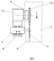
- einen Ausschnitt in der Draufsicht A bei Eingriff der Sägeblätter und der Trennscheibe,
- Figur 3
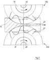
- einen Längsschnitt beim Eingriff der beiden Sägeblätter,
- Figur 4
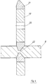
- einen Querschnitt beim Eingriff der beiden Sägeblätter,
- Figur 5
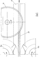
- einen Längsschnitt beim Eingriff der Trennscheibe,
- Figur 6
- einen Querschnitt beim Eingriff der Trennscheibe.
- Wie aus der Zeichnung ersichtlich wird, ist nach Figur 1 auf dem Grundgestell der Kreuztisch 2 aufgebaut mit den Achsen X-3 und Y-4. Der Antrieb 5 der X-Achse ist ebenfalls ersichtlich. Auf der Anschlußfläche der Y-Achse 4 ist der Rundschattisch 6 angeordnet, auf welchem die Aufspannplatte 7 angeschraubt ist. Die Leiterplatte 8 liegt hierauf (7) und damit auf dem Rundschalttisch 6 und zwar mittels der Positionierhilfen 9 oder in einer anderen Ausführung mittels Vakuum in ihrer Lage fixiert. Die beiden Sägeblätter 10a und 10b sind in den Lagerböcken 11a und 11b gelagert und werden über einen gemeinsamen Zahnriemen oder in einer anderen Ausführung ein Getriebe, die beide Sägeblätterantriebe formschlüssig verbinden, vom Motor 12 angetrieben. Die Lagerböcke 11a und 11b können über die Verstellspindel 13 verstellt werden, um an unterschiedliche Sägeblätter und Leiterplattendicken angepaßt zu werden.
- Nach Figur 2 mit Ansicht A als Ausschnitt auf die Vorrichtung, befindet sich die Leiterplatte 8 in der Arbeitsstation, d.h. beim Besäumen mit den Sägeblättern 10a und 10b. Die Leiterplatte 8 wird während des Sägens von zwei übereinanderliegenden Andruckrollen 14 zentriert. Das vollständige Abtrennen des Randes 15 erfolgt mit der Trennscheibe 16, die von einem Motor 17 angetrieben ist, der zum Leiterplatten-Durchgang querverschiebbar auf einer Konsole montiert ist. Nachdem der Rand vollständig abgetrennt ist, fällt er seitlich aus der Vorrichtung heraus.
- In Figur 3 ist verdeutlicht, wie die beiden Sägeblätter 10a und 10b in die Leiterplatte 8 eingreifen, wobei die über die Achsbohrungen 20 aufgenommenen Grundkörper 19 am Umfang mit mehreren Diamant-Schneidzähnen besetzt sind. Schneidzähne 21 sind so ausgebildet, daß sie die Leiterplatte 8 gleichzeitig einschneiden und profilieren, wie aus Fig. 4 ersichtlich, unter einem wählbaren Winkel W zur Sägeblatt-Mitte.
- Aus Figur 3 und 4 wird außerdem die Anordnung der Sägeblätter mit Spitze gegenüber Spitze deutlich und die Ausbildung des Reststeges 22.
- In Figur 5 ist die prinzipielle Anordnung der Trennscheibe 16 gegenüber den Sägeblättern 10a und 10b und der Leiterplatte 8 gezeigt. Wie ersichtlich, bleibt nach der Bearbeitung mit den beiden Sägeblättern ein Reststeg 22 stehen, der von der Trennscheibe 16 erst vollständig durchgetrennt wird.
- In Figur 6 ist schließlich im Querschnitt gezeigt, wie die Trennscheibe 16 in die Leiterplatte 8 eingreift, und wie das Profil der Kante 23 an der Leiterplatte nach vollständiger Bearbeitung aussieht. Hieraus ist außerdem ersichtlich, wie sich das Profil der Kante 23 verändert, wenn die Trennscheibe 16 um den Betrag V axial querverschoben wird.
Claims (5)
- Vorrichtung zum Trennen und Besäumen von Leiterplatten bzw. Leiterplattennutzen, insbes. von dünnen sowie mehrlagigen Leiterplatten,
gekennzeichnet durch zwei in einer Ebene einander gegenüberliegend angeordnete Kreissägeblätter, vorzugsweise mit Diamantschneiden, deren Sägezähne in einem geringen Abstand zueinander mit Spitze gegen Spitze angeordnet sind und synchron angetrieben werden, ohne daß sie die Leterplatte vollständig durchtrennen, und zu diesen unmittelbar anschließend in derselben Ebene eine Trennscheibe angeordnet ist, welche die vollständige Trennung der Leiterplatte vom Rand bewirkt. - Vorrichtung nach Anspruch 1,
dadurch gekennzeichnet, daß die Trennscheibe axial querverschiebbar ist und so ein variables Kantenprofil an der Leiterplatte erzeugbar ist. - Vorrichtung nach Anspruch 1,
dadurch gekennzeichnet, daß die Sägeblätter bei sich nicht berührenden Sägezähnen mit variabler Eintauchtiefe angeordnet sind. - Vorrichtung nach Anspruch 1,
dadurch gekennzeichnet, daß die Verstellung der Sägeblätter zueinander über eine manuell betätigte oder eine mit einem Regelantrieb betätigte, z.B. CNC-gesteuerte Spindel erfolgt. - Vorrichtung nach Anspruch 1,
dadurch gekennzeichnet, daß die Verstellung der Trennscheibe in axialer, quer zum Leiterplatten-Durchgang manuell oder mittels eines Regelantriebes, z.B. CNC-gesteuert, erfolgt.
Applications Claiming Priority (2)
| Application Number | Priority Date | Filing Date | Title |
|---|---|---|---|
| DE4035792A DE4035792C1 (en) | 1990-11-10 | 1990-11-10 | Printed circuit board panel de-edging device - has two saw-blades mounted in bearingblockings which can be positionally adjusted |
| DE4035792 | 1990-11-10 |
Publications (3)
| Publication Number | Publication Date |
|---|---|
| EP0485790A2 true EP0485790A2 (de) | 1992-05-20 |
| EP0485790A3 EP0485790A3 (en) | 1992-09-23 |
| EP0485790B1 EP0485790B1 (de) | 1995-08-30 |
Family
ID=6417999
Family Applications (1)
| Application Number | Title | Priority Date | Filing Date |
|---|---|---|---|
| EP91118290A Expired - Lifetime EP0485790B1 (de) | 1990-11-10 | 1991-10-26 | Vorrichtung zum Trennen und Besäumen von Leiterplatten |
Country Status (4)
| Country | Link |
|---|---|
| EP (1) | EP0485790B1 (de) |
| JP (1) | JPH07100790A (de) |
| AT (1) | ATE127315T1 (de) |
| DE (2) | DE4035792C1 (de) |
Cited By (6)
| Publication number | Priority date | Publication date | Assignee | Title |
|---|---|---|---|---|
| US6783620B1 (en) | 1998-10-13 | 2004-08-31 | Matsushita Electronic Materials, Inc. | Thin-laminate panels for capacitive printed-circuit boards and methods for making the same |
| US6789298B1 (en) | 1998-10-13 | 2004-09-14 | Matsushita Electronic Materials, Inc. | Finishing method for producing thin-laminate panels |
| EP1359612A3 (de) * | 2002-04-24 | 2006-04-19 | Sanyo Electric Co., Ltd. | Verfahren zur Herstellung einer integrierten Hybridschaltungsanordnung |
| US7368633B2 (en) | 1997-06-06 | 2008-05-06 | E.I. Du Pont De Nemours And Company | Plant amino acid biosynthetic enzymes |
| JP2016132107A (ja) * | 2015-01-16 | 2016-07-25 | ショーダテクトロン株式会社 | 分割溝形成装置および分割溝形成方法 |
| CN113681612A (zh) * | 2021-08-30 | 2021-11-23 | 深圳市埃西尔电子有限公司 | 一种电路板高效切割装置 |
Families Citing this family (6)
| Publication number | Priority date | Publication date | Assignee | Title |
|---|---|---|---|---|
| JP2832349B2 (ja) * | 1987-11-24 | 1998-12-09 | チッソ株式会社 | ツイストネマチツク方式用液晶組成物 |
| JP7045126B2 (ja) * | 2015-01-16 | 2022-03-31 | ショーダテクトロン株式会社 | 基板切断装置および基板切断方法 |
| CN105818177A (zh) * | 2016-04-29 | 2016-08-03 | 英拓自动化机械(深圳)有限公司 | 电路板裁切刀具及其裁切电路板的方法 |
| CN108890717A (zh) * | 2018-06-13 | 2018-11-27 | 肇庆高新区国专科技有限公司 | 一种自动旋转裁板装置 |
| CN108748338A (zh) * | 2018-06-22 | 2018-11-06 | 肇庆高新区国专科技有限公司 | 一种自动旋转裁板装置 |
| CN112388694A (zh) * | 2020-10-29 | 2021-02-23 | 深圳市诺信德科技有限公司 | 一种全自动pcb分板机吸尘机构 |
Family Cites Families (3)
| Publication number | Priority date | Publication date | Assignee | Title |
|---|---|---|---|---|
| DE2159427A1 (de) * | 1971-12-01 | 1973-06-07 | Ottokar Cerv | Vorrichtung zur bearbeitung von plattenfoermigen werkstuecken |
| FR2457734A1 (fr) * | 1979-06-01 | 1980-12-26 | Orleans Atel Outillage | Perfectionnements apportes aux procedes et machines du genre de ceux pour rainurer des plaques, notamment a circuits imprimes |
| DE3737868A1 (de) * | 1987-11-07 | 1989-05-18 | Loehr & Herrmann Gmbh | Vorrichtung zum trennen und besaeumen von leiterplatten |
-
1990
- 1990-11-10 DE DE4035792A patent/DE4035792C1/de not_active Expired - Fee Related
-
1991
- 1991-10-26 AT AT91118290T patent/ATE127315T1/de not_active IP Right Cessation
- 1991-10-26 DE DE59106366T patent/DE59106366D1/de not_active Expired - Fee Related
- 1991-10-26 EP EP91118290A patent/EP0485790B1/de not_active Expired - Lifetime
- 1991-11-06 JP JP3318398A patent/JPH07100790A/ja active Pending
Cited By (7)
| Publication number | Priority date | Publication date | Assignee | Title |
|---|---|---|---|---|
| US7368633B2 (en) | 1997-06-06 | 2008-05-06 | E.I. Du Pont De Nemours And Company | Plant amino acid biosynthetic enzymes |
| US6783620B1 (en) | 1998-10-13 | 2004-08-31 | Matsushita Electronic Materials, Inc. | Thin-laminate panels for capacitive printed-circuit boards and methods for making the same |
| US6789298B1 (en) | 1998-10-13 | 2004-09-14 | Matsushita Electronic Materials, Inc. | Finishing method for producing thin-laminate panels |
| US7018703B2 (en) | 1998-10-13 | 2006-03-28 | Matsushita Electric Works, Ltd. | Thin-laminate panels for capacitive printed-circuit boards and methods for making the same |
| EP1359612A3 (de) * | 2002-04-24 | 2006-04-19 | Sanyo Electric Co., Ltd. | Verfahren zur Herstellung einer integrierten Hybridschaltungsanordnung |
| JP2016132107A (ja) * | 2015-01-16 | 2016-07-25 | ショーダテクトロン株式会社 | 分割溝形成装置および分割溝形成方法 |
| CN113681612A (zh) * | 2021-08-30 | 2021-11-23 | 深圳市埃西尔电子有限公司 | 一种电路板高效切割装置 |
Also Published As
| Publication number | Publication date |
|---|---|
| JPH07100790A (ja) | 1995-04-18 |
| DE59106366D1 (de) | 1995-10-05 |
| DE4035792C1 (en) | 1992-04-23 |
| EP0485790B1 (de) | 1995-08-30 |
| EP0485790A3 (en) | 1992-09-23 |
| ATE127315T1 (de) | 1995-09-15 |
Similar Documents
| Publication | Publication Date | Title |
|---|---|---|
| EP0315739B1 (de) | Vorrichtung zum Trennen und Besäumen von Leiterplatten | |
| EP0259716A2 (de) | Verfahren und Vorrichtung zur Aufteilung metallkaschierter Laminatbahnen in einzelne Platten | |
| EP0485790B1 (de) | Vorrichtung zum Trennen und Besäumen von Leiterplatten | |
| DE69804240T2 (de) | Zentriervorrichtung für doppeltverzahnte zahnräder und verfahren zur herstellung von derartigen zahnrädern | |
| EP1925410A2 (de) | Verfahren und Maschine zum Aufteilen einer grossformatigen Rohplatte | |
| EP0838313A1 (de) | Verfahren und Vorrichtung zum Einrichten von paarweise zusammenwirkenden Werkzeugen | |
| EP1815931B1 (de) | Vorritzsägeblätter und ihr Einstellverfahren | |
| DE3832215A1 (de) | Trennschneidvorrichtung | |
| EP1005938A2 (de) | Sägeblattschärfmaschine mit unabhängigen Zahnflankenschleifköpfen | |
| DE2752912C2 (de) | Schneidpresse zur Bearbeitung plattenförmiger Werkstücke aus Blech od. dgl. | |
| DE4323890A1 (de) | Vorrichtung zum Profilieren und Entgraten von Leiterplatten | |
| DE4217228C1 (de) | Trennmaschine fuer baumaterialien, vorzugsweise naturstein | |
| EP0841116B1 (de) | Verfahren zum Bearbeiten von rotationssymmetrischen Werkstückflächen sowie Werkzeug zur Durchführung eines solchen Verfahrens | |
| DE1942538B2 (de) | Universal-Steinbearbeitungsmaschine | |
| DE3700754A1 (de) | Schaftfraeser | |
| EP0620081B1 (de) | Verfahren zur Positionierung eines einen Bezugspunkt aufweisenden Maschinenelementes, vorzugsweise eines Bearbeitungswerkzeuges, relativ zu einem Referenzpunkt, vorzugsweise zu einem Anschlag oder einer Auflagefläche | |
| DE10049662C2 (de) | Vorrichtung und Verfahren zum Wälzfräsen des variablen Längsprofils von Schlüsseln für Zylinderschlösser | |
| EP1412149B1 (de) | Wafer-schneidemaschine | |
| EP1121217B1 (de) | Vorrichtung und verfahren zum herstellen von platinen | |
| DE2535583A1 (de) | Verfahren zum schaerfen von kreissaegen sowie saegenschaerfmaschine zum durchfuehren des verfahrens | |
| DE2907304A1 (de) | Verfahren zur herstellung von endprofilen an einem werkstueck | |
| DE19917537C5 (de) | Holzbearbeitungsmaschine mit einer Korrekturvorrichtung | |
| DE2415006A1 (de) | Verfahren und vorrichtung zur herstellung von fensterrahmen mit glashalteleiste aus holz | |
| DE29619899U1 (de) | Schneideinrichtung zum Zuschneiden von Profilleisten | |
| DE102019108575A1 (de) | Verfahren zum Ausfräsen von plattenförmigen Werkstücken aus einer Materialplatte |
Legal Events
| Date | Code | Title | Description |
|---|---|---|---|
| PUAI | Public reference made under article 153(3) epc to a published international application that has entered the european phase |
Free format text: ORIGINAL CODE: 0009012 |
|
| AK | Designated contracting states |
Kind code of ref document: A2 Designated state(s): AT BE CH DE FR GB IT LI LU NL SE |
|
| PUAL | Search report despatched |
Free format text: ORIGINAL CODE: 0009013 |
|
| AK | Designated contracting states |
Kind code of ref document: A3 Designated state(s): AT BE CH DE FR GB IT LI LU NL SE |
|
| 17P | Request for examination filed |
Effective date: 19930322 |
|
| 17Q | First examination report despatched |
Effective date: 19931109 |
|
| GRAA | (expected) grant |
Free format text: ORIGINAL CODE: 0009210 |
|
| AK | Designated contracting states |
Kind code of ref document: B1 Designated state(s): AT BE CH DE FR GB IT LI LU NL SE |
|
| REF | Corresponds to: |
Ref document number: 127315 Country of ref document: AT Date of ref document: 19950915 Kind code of ref document: T |
|
| REF | Corresponds to: |
Ref document number: 59106366 Country of ref document: DE Date of ref document: 19951005 |
|
| PG25 | Lapsed in a contracting state [announced via postgrant information from national office to epo] |
Ref country code: LU Free format text: LAPSE BECAUSE OF NON-PAYMENT OF DUE FEES Effective date: 19951031 |
|
| ITF | It: translation for a ep patent filed | ||
| GBT | Gb: translation of ep patent filed (gb section 77(6)(a)/1977) |
Effective date: 19951023 |
|
| ET | Fr: translation filed | ||
| PLBE | No opposition filed within time limit |
Free format text: ORIGINAL CODE: 0009261 |
|
| STAA | Information on the status of an ep patent application or granted ep patent |
Free format text: STATUS: NO OPPOSITION FILED WITHIN TIME LIMIT |
|
| 26N | No opposition filed | ||
| PGFP | Annual fee paid to national office [announced via postgrant information from national office to epo] |
Ref country code: BE Payment date: 19961004 Year of fee payment: 6 |
|
| PGFP | Annual fee paid to national office [announced via postgrant information from national office to epo] |
Ref country code: AT Payment date: 19961014 Year of fee payment: 6 |
|
| PGFP | Annual fee paid to national office [announced via postgrant information from national office to epo] |
Ref country code: GB Payment date: 19961017 Year of fee payment: 6 |
|
| PGFP | Annual fee paid to national office [announced via postgrant information from national office to epo] |
Ref country code: SE Payment date: 19961018 Year of fee payment: 6 |
|
| PGFP | Annual fee paid to national office [announced via postgrant information from national office to epo] |
Ref country code: CH Payment date: 19961024 Year of fee payment: 6 |
|
| PGFP | Annual fee paid to national office [announced via postgrant information from national office to epo] |
Ref country code: FR Payment date: 19961029 Year of fee payment: 6 |
|
| PGFP | Annual fee paid to national office [announced via postgrant information from national office to epo] |
Ref country code: NL Payment date: 19961031 Year of fee payment: 6 |
|
| PG25 | Lapsed in a contracting state [announced via postgrant information from national office to epo] |
Ref country code: GB Free format text: LAPSE BECAUSE OF NON-PAYMENT OF DUE FEES Effective date: 19971026 Ref country code: AT Free format text: LAPSE BECAUSE OF NON-PAYMENT OF DUE FEES Effective date: 19971026 |
|
| PG25 | Lapsed in a contracting state [announced via postgrant information from national office to epo] |
Ref country code: SE Free format text: LAPSE BECAUSE OF NON-PAYMENT OF DUE FEES Effective date: 19971027 |
|
| PG25 | Lapsed in a contracting state [announced via postgrant information from national office to epo] |
Ref country code: LI Free format text: LAPSE BECAUSE OF NON-PAYMENT OF DUE FEES Effective date: 19971031 Ref country code: FR Free format text: THE PATENT HAS BEEN ANNULLED BY A DECISION OF A NATIONAL AUTHORITY Effective date: 19971031 Ref country code: CH Free format text: LAPSE BECAUSE OF NON-PAYMENT OF DUE FEES Effective date: 19971031 Ref country code: BE Free format text: LAPSE BECAUSE OF NON-PAYMENT OF DUE FEES Effective date: 19971031 |
|
| BERE | Be: lapsed |
Owner name: LOHR & HERRMANN G.M.B.H. Effective date: 19971031 |
|
| PG25 | Lapsed in a contracting state [announced via postgrant information from national office to epo] |
Ref country code: NL Free format text: LAPSE BECAUSE OF NON-PAYMENT OF DUE FEES Effective date: 19980501 |
|
| REG | Reference to a national code |
Ref country code: CH Ref legal event code: PL |
|
| GBPC | Gb: european patent ceased through non-payment of renewal fee |
Effective date: 19971026 |
|
| NLV4 | Nl: lapsed or anulled due to non-payment of the annual fee |
Effective date: 19980501 |
|
| EUG | Se: european patent has lapsed |
Ref document number: 91118290.5 |
|
| REG | Reference to a national code |
Ref country code: FR Ref legal event code: ST |
|
| PGFP | Annual fee paid to national office [announced via postgrant information from national office to epo] |
Ref country code: DE Payment date: 20010927 Year of fee payment: 11 |
|
| PG25 | Lapsed in a contracting state [announced via postgrant information from national office to epo] |
Ref country code: DE Free format text: LAPSE BECAUSE OF NON-PAYMENT OF DUE FEES Effective date: 20030501 |
|
| PG25 | Lapsed in a contracting state [announced via postgrant information from national office to epo] |
Ref country code: IT Free format text: LAPSE BECAUSE OF NON-PAYMENT OF DUE FEES Effective date: 20051026 |