EP0485792A2 - Procédé de coupage aux gaz sous un liquide - Google Patents
Procédé de coupage aux gaz sous un liquide Download PDFInfo
- Publication number
- EP0485792A2 EP0485792A2 EP91118311A EP91118311A EP0485792A2 EP 0485792 A2 EP0485792 A2 EP 0485792A2 EP 91118311 A EP91118311 A EP 91118311A EP 91118311 A EP91118311 A EP 91118311A EP 0485792 A2 EP0485792 A2 EP 0485792A2
- Authority
- EP
- European Patent Office
- Prior art keywords
- oxygen
- heating
- fuel gas
- cutting
- nozzle
- Prior art date
- Legal status (The legal status is an assumption and is not a legal conclusion. Google has not performed a legal analysis and makes no representation as to the accuracy of the status listed.)
- Withdrawn
Links
Images

Classifications
-
- B—PERFORMING OPERATIONS; TRANSPORTING
- B23—MACHINE TOOLS; METAL-WORKING NOT OTHERWISE PROVIDED FOR
- B23K—SOLDERING OR UNSOLDERING; WELDING; CLADDING OR PLATING BY SOLDERING OR WELDING; CUTTING BY APPLYING HEAT LOCALLY, e.g. FLAME CUTTING; WORKING BY LASER BEAM
- B23K7/00—Cutting, scarfing, or desurfacing by applying flames
- B23K7/08—Cutting, scarfing, or desurfacing by applying flames by applying additional compounds or means favouring the cutting, scarfing or desurfacing procedure
Definitions
- the invention relates to a method for flame cutting under a liquid according to the preamble of claim 1 and a device for carrying out the method according to the preamble of claim 9.
- the workpiece surface When flame cutting in the atmosphere, the workpiece surface is heated with a fuel gas-oxygen flame of a gas burner to at least the ignition temperature of the material, then cutting oxygen oxidizes part of the kerf material and the very strongly exothermic combustion reaction provides the heat for melting the neighboring material.
- the melt which consists of oxides and non-oxidized metal, is blown out of the kerf by the residual jet of the cutting oxygen.
- the crucial part of the gas burner is the flame cutting nozzle; it forms the cutting oxygen jet, the actual tool for flame cutting.
- Outlet openings for the heating flames are arranged rotationally symmetrically around the cutting oxygen jet in order to be able to cut in all horizontal directions when the cutting oxygen jet is blowing vertically downwards.
- the faster burning fuel gas acetylene is an advantage in most applications.
- the greatest possible cutting speeds depend on the properties of the cutting oxygen jet and on the thickness of the workpieces and on the material. The quality of the cut surface also limits the cutting speed.
- the heating flame is set with valves.
- fuel gas and oxygen are mixed in a ratio of 1 (fuel gas) to 1.1 to 1.3 (heating oxygen).
- the combustion of this gas mixture is incomplete.
- the resulting gases, carbon oxide and hydrogen, form an oxygen-free (reducing) zone in the flame.
- the oxygen required for the complete combustion of the fuel gas / heating oxygen mixture is taken from the surrounding air by the flame jacket.
- the invention has for its object to provide a method by means of which gas burners are used for thermal separation under water can be. This object is achieved by the characterizing features of claim 1.
- the invention has surprisingly shown that with an oxyacetylene burner under a liquid, preferably water, flame cuts with a cutting quality of the cutting surface in accordance with DIN 2310, Part 3, quality class 1 can be produced at almost the same cutting speed.
- the quality of the cut surfaces cut under water is better because the continuous cooling of the material area immediately adjacent to the cutting point results in a balanced heat balance over the entire material thickness, which prevents melting of the kerf on the material surface as well as deflection of the cutting oxygen jet on the exit side of the kerfs. Almost parallel cutting surfaces with the lowest chasing are achieved.
- a training example is shown in the drawing and is described in more detail below.
- a device for thermal flame cutting is designated by 1 in FIG. 1.
- the gas burner 20, shown only schematically, has a cutting nozzle 2.
- the cutting oxygen channel 3, which is arranged centrally in the cutting nozzle 2, is surrounded in a rotationally symmetrical manner by heating gas channels 4 and is connected to an oxygen supply 24 via a cutting oxygen supply 5 with a valve 40, which can preferably be controlled electrically.
- a heating gas mixture is generated in the annular space 21 connected to the heating gas channels 4, which is connected on the input side via a heating oxygen supply 22 and a fuel gas supply 23 to an oxygen supply 24 and a fuel gas supply 25.
- injector gas burner in which the mixture of fuel gas and heating oxygen takes place in an injector of the burner, instead of the gas-mixing nozzle of the gas burner 20.
- injector gas burners are known and therefore do not need to be described in more detail.
- a separate ignition gas mixture supply 6 opens into the cutting oxygen supply 5 connected to the cutting oxygen channel 3 and is connected to a fuel gas and oxygen supply 24, 25 via an injector 34 and preferably electrically controllable valves 31, 33.
- An electrical igniter 8, which is connected to the cutting oxygen supply 5, is arranged inside the gas burner 20 opposite the outflow opening of the ignition gas mixture supply 6.
- the ignition device 8 consists essentially of an ignition electrode with an opposite ground pin, with which an ignition spark is generated.
- the cutting nozzle 2 is positively surrounded by a gas jet nozzle 9 at least in the area of the outflow openings 27, 28 of the heating gas channels 4 and the cutting oxygen channel 3.
- the gas jet nozzle 9 can protrude flush with the cutting nozzle or up to 5 mm. As a result, stabilization can be achieved with slowly burning fuel gases.
- An outlet opening 10 is provided in the gas jet nozzle 9 and is connected to an oxygen supply 12 via a blowing oxygen supply 11 and a valve 7.
- the axis 13 of the outflow opening 10 extends at an angle 14 between 10 ° and 45 °, but preferably at an angle of 25 °. That of the device 1 assigned water basin is designated in its entirety with 15, the water surface with 16. The structure and functioning of such water basins are known and therefore do not need to be explained in more detail.
- a workpiece 17 is arranged on a flame cutting table, not shown; the surface of the workpiece is designated 18.
- valves 7, 26, 29, 30, 31, 33, 40 are preferably designed as a proportional pressure valve.
- the facility works as follows: The data for the corresponding process steps of the flame cutting process are stored in the computer 32 (microprocessor) in a memory in which further data such as the type of material, workpiece thickness and the like are stored.
- the gas burner 20 with the gas jet nozzle 9 assigned to it is arranged in a parking position above the water surface 16.
- the valve 33 receives the "ignition oxygen on” signal. Ignition oxygen now flows via the ignition gas mixture supply 6 into the cutting oxygen channel 3 and exits from the outlet opening 28.
- the valve 29 receives the "heating oxygen on” signal from the computer 32 via the control lines shown in dashed lines.
- the valve 7 is opened so that oxygen preferably exits the outflow opening 10 in the form of a jet.
- the gas burner 20 is on the Move the burner height and side drives, not shown, from the park position to the heating position, immersing them in the water basin 15.
- the valve 33 and valve 31 are opened. Pilot fuel gas and pilot oxygen mix in the injector 34 and flow as a pilot fuel gas mixture into the area of the igniter 8 and out of the outflow opening 28; Heating fuel gas mixes in the annular space 21 with the heating oxygen and flows as a heating gas mixture from the outflow opening 27 of the heating gas channels.
- the proportion of fuel gas, preferably of the fuel gas acetylene, in the fuel gas / heating oxygen mixture produced, based on the proportion of heating oxygen, is greater (excess fuel gas).
- the proportion must be greater than 1.7 and less than 2.5 times the proportion of heating oxygen, the quality of the cut surfaces 37 at almost atmospheric cutting speeds being greater than 1.8 and less than 2.2, preferably 1 , 85, of the fuel gas, based on the proportion of heating oxygen, are most advantageous.
- the ignition device 8 receives the control command "Ignition" from the computer 32 with a time delay.
- the ignition gas mixture is ignited via the ignition spark or spark.
- the pilot flame emerges from the outflow opening 28 for the "cutting oxygen” and ignites the fuel gas / heating oxygen mixture with an increased fuel gas content.
- the ignition is switched off, the valve 31 for the pilot fuel gas is closed and the oxygen pressure emerging from the outflow opening 10 is reduced.
- the gas burner 20 now runs by means of its side and Height drives to a predetermined position, preferably above the workpiece surface 18 and preheats it for the piercing process until the ignition temperature of the material is reached.
- the pressure of the heating oxygen is increased until the ignition temperature of the material is reached.
- the pressure of the heating oxygen is reduced and the cutting oxygen is switched on.
- the ignition oxygen is automatically switched off when the cutting oxygen is switched on via a lock.
- the valve 23 is closed.
- the cutting torch is then moved via drives according to the predetermined coordinates and the workpiece is flame cut, a fuel gas / heating oxygen mixture with excess fuel gas escaping from the flame cutting nozzle, and then oxygen is mixed in outside the torch nozzle via the oxygen jet emerging from the outlet opening 10.
- the cutting oxygen is switched off and the ignition oxygen is put in by coupling.
- the heating fuel gas is switched off and the burner is moved over the water surface 16.
- the ignition oxygen, the heating oxygen and the oxygen emerging from the outflow opening 10, which prevent the liquid from entering the gas burner, are then switched off.
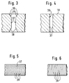
- a kerf and a cutting surface is shown as it forms after the flame cut in the atmosphere.
- the kerf according to FIG. 3 has a conical inlet 35 with edges 36 rounded to the workpiece surface 18, which continues in the central thickness region of the workpiece 17 with essentially parallel cutting surfaces 37.
- a conical widening 38 of the cut surfaces 37 takes place on the exit side of the cutting oxygen jet. This creates 37 comma-like grooves 39 on the cut surfaces, which curve in opposite directions or to the cutting direction.
- the kerf cut by flame according to the invention under a liquid according to FIG. 4 has almost parallel cutting surfaces 37 over the entire workpiece thickness, only the edges of the workpiece surface 18 and the workpiece lower surface being slightly rounded.
- FIG. 6 shows the course of the grooves 39 on the cutting surfaces 37 of carbon-containing steels flame-cut under a liquid. As can be seen from the illustration, the grooves 39 run almost straight.
Landscapes
- Engineering & Computer Science (AREA)
- Mechanical Engineering (AREA)
- Gas Burners (AREA)
Applications Claiming Priority (2)
| Application Number | Priority Date | Filing Date | Title |
|---|---|---|---|
| DE4036486 | 1990-11-16 | ||
| DE19904036486 DE4036486A1 (de) | 1990-11-16 | 1990-11-16 | Verfahren zum brennschneiden unter einer fluessigkeit |
Publications (1)
| Publication Number | Publication Date |
|---|---|
| EP0485792A2 true EP0485792A2 (fr) | 1992-05-20 |
Family
ID=6418354
Family Applications (1)
| Application Number | Title | Priority Date | Filing Date |
|---|---|---|---|
| EP91118311A Withdrawn EP0485792A2 (fr) | 1990-11-16 | 1991-10-28 | Procédé de coupage aux gaz sous un liquide |
Country Status (2)
| Country | Link |
|---|---|
| EP (1) | EP0485792A2 (fr) |
| DE (1) | DE4036486A1 (fr) |
Cited By (2)
| Publication number | Priority date | Publication date | Assignee | Title |
|---|---|---|---|---|
| FR2766397A1 (fr) * | 1997-07-22 | 1999-01-29 | Metallurg Marnaise Soc | Procede et installation de decoupage par oxycoupage d'au moins une plaque en acier trempe |
| CN116571869A (zh) * | 2023-05-30 | 2023-08-11 | 西南石油大学 | 一种压力环境中使用的金属管柱热熔切割装置 |
-
1990
- 1990-11-16 DE DE19904036486 patent/DE4036486A1/de not_active Withdrawn
-
1991
- 1991-10-28 EP EP91118311A patent/EP0485792A2/fr not_active Withdrawn
Cited By (2)
| Publication number | Priority date | Publication date | Assignee | Title |
|---|---|---|---|---|
| FR2766397A1 (fr) * | 1997-07-22 | 1999-01-29 | Metallurg Marnaise Soc | Procede et installation de decoupage par oxycoupage d'au moins une plaque en acier trempe |
| CN116571869A (zh) * | 2023-05-30 | 2023-08-11 | 西南石油大学 | 一种压力环境中使用的金属管柱热熔切割装置 |
Also Published As
| Publication number | Publication date |
|---|---|
| DE4036486A1 (de) | 1992-05-21 |
Similar Documents
| Publication | Publication Date | Title |
|---|---|---|
| EP0017807B1 (fr) | Procédé pour évites la formation des bavures lors du découpage au chalumeau des produits métalliques et dispositif pour sa mise en oeuvre | |
| DE3321697C2 (fr) | ||
| DE3718597A1 (de) | Schneidbrenner | |
| DE549781C (de) | Verfahren zum Brennschneiden von Gusseisen | |
| DE2841704A1 (de) | Verfahren und vorrichtung zum thermochemischen flaemmen eines metallischen werkstueckes | |
| EP0485792A2 (fr) | Procédé de coupage aux gaz sous un liquide | |
| DE4016181A1 (de) | Verfahren und vorrichtung zum laserstrahlbrennschneiden | |
| DE7109493U (de) | Brennschneid und Markierungsvor richtung | |
| DE3912988A1 (de) | Verfahren zum berussen von flaechen von gegenstaenden mit einem brenner | |
| DE2855499C2 (de) | Aufblaslanze | |
| DE3721685A1 (de) | Bandguss-brennschneidmaschine in stranggiessanlagen | |
| DE2720793A1 (de) | Verfahren und vorrichtung zum durchfuehren von thermochemischen schnellstarts | |
| DE557598C (de) | Verfahren und Vorrichtung zum Betriebe von Schmelzoefen, insbesondere Siemens-Martin-OEfen | |
| DE3921455C1 (en) | Flame cutting machine - has two or more torches with adjustment for height above workpiece and oxygen supply lines | |
| DE4033618A1 (de) | Verfahren zum unterwasserschneiden | |
| EP0134907A1 (fr) | Dispositif pour l'amenée d'un milieu gazeux sous forme d'impulsion dans un four de calcination, etc. | |
| DE2112083C (de) | Brennschneid und Markierungs vorrichtung und Verfahren zum Markie ren unter Verwendung dieser Vorrich tung | |
| DE2553553C2 (de) | Vorrichtung zum Flammen eines Werkstuckes | |
| DE3149477C2 (fr) | ||
| DE2321853B2 (de) | Verfahren und Düse zum Behandeln von Metallschmelzen mit Fluidstrahler! | |
| DE1901923A1 (de) | Verfahren und Vorrichtung zum Brennstrahl-Schlitzen | |
| DE1529194C (de) | Schweißbrennereinsatz | |
| DE1451428B1 (de) | Fluessigstoffbrenner fuer metallurgische OEfen | |
| AT276011B (de) | Gasschneidbrenner | |
| DE1627569C (de) | Einrichtung zum Einleiten eines, insbesondere von einer beliebigen Stelle der Werkstückoberfläche ausgehenden, Schneidvorganges an autogenen Brennschneidmaschinen |
Legal Events
| Date | Code | Title | Description |
|---|---|---|---|
| PUAI | Public reference made under article 153(3) epc to a published international application that has entered the european phase |
Free format text: ORIGINAL CODE: 0009012 |
|
| AK | Designated contracting states |
Kind code of ref document: A2 Designated state(s): BE DE ES FR GB IT NL SE |
|
| STAA | Information on the status of an ep patent application or granted ep patent |
Free format text: STATUS: THE APPLICATION HAS BEEN WITHDRAWN |
|
| 18W | Application withdrawn |
Withdrawal date: 19920625 |
|
| R18W | Application withdrawn (corrected) |
Effective date: 19920625 |