EP0485800A1 - Elektromagnetisches Ventil mit eingebautem Filter im Anker - Google Patents
Elektromagnetisches Ventil mit eingebautem Filter im Anker Download PDFInfo
- Publication number
- EP0485800A1 EP0485800A1 EP91118424A EP91118424A EP0485800A1 EP 0485800 A1 EP0485800 A1 EP 0485800A1 EP 91118424 A EP91118424 A EP 91118424A EP 91118424 A EP91118424 A EP 91118424A EP 0485800 A1 EP0485800 A1 EP 0485800A1
- Authority
- EP
- European Patent Office
- Prior art keywords
- valve
- armature
- flow
- solenoid
- filter
- Prior art date
- Legal status (The legal status is an assumption and is not a legal conclusion. Google has not performed a legal analysis and makes no representation as to the accuracy of the status listed.)
- Withdrawn
Links
- 239000012530 fluid Substances 0.000 claims abstract description 29
- 239000011236 particulate material Substances 0.000 claims abstract description 4
- 238000001914 filtration Methods 0.000 claims description 11
- 238000005461 lubrication Methods 0.000 claims description 3
- 230000008901 benefit Effects 0.000 description 3
- 238000010276 construction Methods 0.000 description 3
- 239000002245 particle Substances 0.000 description 2
- 229910001369 Brass Inorganic materials 0.000 description 1
- 230000009286 beneficial effect Effects 0.000 description 1
- 239000010951 brass Substances 0.000 description 1
- 239000000356 contaminant Substances 0.000 description 1
- 230000000694 effects Effects 0.000 description 1
- 238000011010 flushing procedure Methods 0.000 description 1
- 230000001050 lubricating effect Effects 0.000 description 1
- 230000014759 maintenance of location Effects 0.000 description 1
- 238000004519 manufacturing process Methods 0.000 description 1
- 239000000463 material Substances 0.000 description 1
- 238000000034 method Methods 0.000 description 1
- 230000008520 organization Effects 0.000 description 1
- 238000003825 pressing Methods 0.000 description 1
- 238000011144 upstream manufacturing Methods 0.000 description 1
Images
Classifications
-
- F—MECHANICAL ENGINEERING; LIGHTING; HEATING; WEAPONS; BLASTING
- F16—ENGINEERING ELEMENTS AND UNITS; GENERAL MEASURES FOR PRODUCING AND MAINTAINING EFFECTIVE FUNCTIONING OF MACHINES OR INSTALLATIONS; THERMAL INSULATION IN GENERAL
- F16K—VALVES; TAPS; COCKS; ACTUATING-FLOATS; DEVICES FOR VENTING OR AERATING
- F16K31/00—Actuating devices; Operating means; Releasing devices
- F16K31/02—Actuating devices; Operating means; Releasing devices electric; magnetic
- F16K31/06—Actuating devices; Operating means; Releasing devices electric; magnetic using a magnet, e.g. diaphragm valves, cutting off by means of a liquid
- F16K31/0603—Multiple-way valves
- F16K31/061—Sliding valves
- F16K31/0613—Sliding valves with cylindrical slides
Definitions
- This invention relates generally to solenoid-operated fluid valves. More specifically it relates to a solenoid-operated valve which contains a filter medium that is arranged to filter particulate material from fluid that lubricates the interface between the valve armature and the armature guide without imposing a restriction on flow through the fluid circuit controlled by the valve.
- the armature is a cylindrical tube whose motion is guided by closely fitting the tube in a cylindrical bore in the valve body.
- a leakage path for fluid extends longitudinally along the interface that exists between the I.D. of the bore and the O.D. of the tube.
- the leakage fluid provides lubrication for this tube/bore interface.
- the present invention arises through the recognition that the inclusion of a filter medium suitable for removing the objectionable particulates from fluid entering the valve may impose an unacceptable restriction on flow through the fluid circuit controlled by the valve.
- the invention provides a solution to this problem by a novel filter construction and arrangement wherein a filter medium that can filter the tiny objectionable particulates which are capable of intruding into the tube/bore interface is disposed in filtering relation to the leakage flow entering the interface, but in non-filtering relation to the flow that is being controlled by the valve.
- this construction and arrangement comprises a fine mesh filter screen carried by the armature.
- the fine mesh filter screen is part of a filter cartridge that is disposed on the interior of the armature tube in filtering relation to leakage fluid that passes through the tube before it reaches the tube/bore interface.
- This disposition of the filter screen precludes it from having any restrictive effect on the flow that is controlled by the valve.
- the invention provides a significant enhancement to the commercial acceptance of the representative solenoid-operated valves described in the aformentioned patent application. Principles of the invention are applicable to different valve configurations, including two-way and three-way valves.
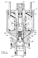
- Fig. 1 is a longitudinal cross sectional view through a solenoid-operated valve embodying principles of the present invention.
- valve 10 is a three-way valve wherein valve body 12 comprises a supply (pressure) port 18, a dump (drain) port 20, and a control port 22.
- Armature 16 carries a valving member in the form of an integral circular shoulder 26 at one end. Shoulder 26 is disposed between a pair of circular valve seats 28 and 30 which are spaced coaxially apart on valve body 12.
- Fig. 1 shows shoulder 26 seated on seat 28 and unseated from seat 30.
- valve seat 30 In this state, the flow path that extends through the valve between supply port 18 and control port 22 and that is circumscribed by valve seat 30 is maximally open while the flow path that extends through the valve between control port 22 and dump port 20 and that is circumscribed by valve seat 28 is fully closed.
- Fig. 1 The state depicted by Fig. 1 occurs when solenoid 14 is fully energized by the application of an appropriate energizing voltage across its input terminals 32 and 34.
- the electromagnetic attractive force that is exerted by solenoid 14 on armature 16 is urging the armature up as viewed in Fig. 1 and is further compressing a helical coil spring 36 that tends to urge the armature down.
- spring 36 will move armature 16 down to cause shoulder 26 to unseat from seat 28 and seat on seat 30, in which event the flow path between supply port 18 and control port 22 is fully closed and the flow path between control port 22 and dump port 20 is maximally open.
- An adjustment mechanism 24 provides for the force of spring 36 to be pre-set to a desired intensity.
- the illustrated valve is especially well suited for operation as a proportional control valve that can be pulse width modulated.
- the application of a pulse width modulated electrical signal across terminals 32 and 34 will cause the fluid pressures at supply port 18 and dump port 20 to be pulse width modulated to control port 22.
- Armature 16 has a circular cylindrical shape that provides a longitudinal through-hole 38. In accordance with principles of the invention, it is within through-hole 38 that a filter cartridge 40 is disposed. Armature 16 also has two coaxially spaced apart, circular, annular bearing seals 42 and 44 that extend around its outside. These bearing seals, each of which is in the form of a centrally grooved ridge that is integral with the armature, provide for the closely sealed sliding fit of the armature within a segment of a central circular bore 46 of valve body 12.
- Through-hole 38 serves to convey the fluid pressure at supply port 18 to the zone 48 at the far end of the armature.
- the supply fluid pressure is thereby applied to the top face of bearing seal 42.
- the bottom face of bearing seal 44 is communicated to dump port 20 and is therefore at dump pressure.
- the result is that the pressure difference between supply pressure and dump pressure is applied across the two bearings 42 and 44.
- the bearing seals are highly effective, they are not perfect, and therefore will allow a certain leakage flow along the interface that exists between armature 16 and bore 46. This leakage flow provides a presence of fluid along the armature/bore interface which is beneficial in lubricating the armature's motion.
- Cartridge 40 comprises a cylindrical plastic body 50, a fine mesh screen 52, a brass ring 54, and an end cap 55 in assembled relation.
- Body 50 contains a passage 56 that is open at its lower end as viewed in Fig. 1 and that is also open at its sidewall.
- Cap 55 closes the upper end of the body.
- Screen 52 is formed to a cylindrical shape and disposed around the outside of the sidewall of body 50 in covering relation to the two openings of passage 56 that are in opposite halves of the body's sidewall.
- Ring 54 provides for the press-fit retention of the cartridge in through-hole 38, assembly of the cartridge to the armature being conducted by pressing the cartridge into the armature to a suitable depth.
- the organization and arrangement of the cartridge and armature are such that fluid that has entered the lower end of through-hole 38 is constrained to pass through filter screen 52 before it arrives at zone 48. In this way the fluid is strained by screen 52 before the fluid can reach the armature/bore interface.
- By making the screen mesh sufficiently fine, fluid-entrained particles which might otherwise pass to the armature/bore interface are screened and collected at the upstream face of screen 52. Yet the screen imposes no restriction on the flows between the ports 18, 20, and 22.
- the parts of the filter cartridge can be fabricated from conventional materials by conventional manufacturing techniques.
- body 50 and screen 52 can be plastic.
Landscapes
- Engineering & Computer Science (AREA)
- General Engineering & Computer Science (AREA)
- Mechanical Engineering (AREA)
- Magnetically Actuated Valves (AREA)
- Details Of Valves (AREA)
Applications Claiming Priority (2)
| Application Number | Priority Date | Filing Date | Title |
|---|---|---|---|
| US612355 | 1984-05-21 | ||
| US61235590A | 1990-11-13 | 1990-11-13 |
Publications (1)
| Publication Number | Publication Date |
|---|---|
| EP0485800A1 true EP0485800A1 (de) | 1992-05-20 |
Family
ID=24452810
Family Applications (1)
| Application Number | Title | Priority Date | Filing Date |
|---|---|---|---|
| EP91118424A Withdrawn EP0485800A1 (de) | 1990-11-13 | 1991-10-29 | Elektromagnetisches Ventil mit eingebautem Filter im Anker |
Country Status (2)
| Country | Link |
|---|---|
| EP (1) | EP0485800A1 (de) |
| JP (1) | JPH06109161A (de) |
Cited By (2)
| Publication number | Priority date | Publication date | Assignee | Title |
|---|---|---|---|---|
| EP1336785A3 (de) * | 2002-02-19 | 2003-09-03 | SCHROTT, Harald | Bistabiles elektromagnetisches Ventil |
| EP1336783A3 (de) * | 2002-02-19 | 2003-09-03 | SCHROTT, Harald | Bistabiles elektromagnetisches Ventil |
Families Citing this family (1)
| Publication number | Priority date | Publication date | Assignee | Title |
|---|---|---|---|---|
| JP4667609B2 (ja) * | 2000-02-29 | 2011-04-13 | イーグル工業株式会社 | ソレノイド |
Citations (3)
| Publication number | Priority date | Publication date | Assignee | Title |
|---|---|---|---|---|
| DE2926320A1 (de) * | 1979-06-29 | 1981-01-15 | Sueddeutsche Kuehler Behr | Elektromagnetisches wasserventil mit hydraulischer servoeinheit fuer die regelung des wasserkreislaufes in heizbzw. klimaanlagen von kraftfahrzeugen |
| DE3309904A1 (de) * | 1983-03-18 | 1984-09-20 | Mannesmann Rexroth GmbH, 8770 Lohr | Elektromagnet und magnetventil |
| DE3404188A1 (de) * | 1984-02-07 | 1985-08-08 | Mannesmann Rexroth GmbH, 8770 Lohr | Von einem regelbaren elektromagneten betaetigtes hydraulisches ventil |
-
1991
- 1991-10-29 EP EP91118424A patent/EP0485800A1/de not_active Withdrawn
- 1991-11-12 JP JP29545791A patent/JPH06109161A/ja not_active Withdrawn
Patent Citations (3)
| Publication number | Priority date | Publication date | Assignee | Title |
|---|---|---|---|---|
| DE2926320A1 (de) * | 1979-06-29 | 1981-01-15 | Sueddeutsche Kuehler Behr | Elektromagnetisches wasserventil mit hydraulischer servoeinheit fuer die regelung des wasserkreislaufes in heizbzw. klimaanlagen von kraftfahrzeugen |
| DE3309904A1 (de) * | 1983-03-18 | 1984-09-20 | Mannesmann Rexroth GmbH, 8770 Lohr | Elektromagnet und magnetventil |
| DE3404188A1 (de) * | 1984-02-07 | 1985-08-08 | Mannesmann Rexroth GmbH, 8770 Lohr | Von einem regelbaren elektromagneten betaetigtes hydraulisches ventil |
Non-Patent Citations (2)
| Title |
|---|
| PATENT ABSTRACTS OF JAPAN, vol. 14, no. 364 (M-1007)[4307], 7th August 1990; & JP-A-2 129 480 (AISIN) 17-05-1990 * |
| PATENT ABSTRACTS OF JAPAN, vol. 15, no. 42 (M-1076)[4570], 31st January 1991; & JP-A-2 278 084 (MITSUBISHI) 14-11-1990 * |
Cited By (2)
| Publication number | Priority date | Publication date | Assignee | Title |
|---|---|---|---|---|
| EP1336785A3 (de) * | 2002-02-19 | 2003-09-03 | SCHROTT, Harald | Bistabiles elektromagnetisches Ventil |
| EP1336783A3 (de) * | 2002-02-19 | 2003-09-03 | SCHROTT, Harald | Bistabiles elektromagnetisches Ventil |
Also Published As
| Publication number | Publication date |
|---|---|
| JPH06109161A (ja) | 1994-04-19 |
Similar Documents
| Publication | Publication Date | Title |
|---|---|---|
| US4500067A (en) | Pilot operated low flow valve | |
| CA1037343A (en) | Pressure control valve | |
| US6065734A (en) | Control valve for a hydraulic control unit of vehicular brake systems | |
| DE69721201T2 (de) | Einstufiges, elektromagnetisches Druckregelventil mit einstellbarer Motorkraft | |
| US5133382A (en) | Primary valve actuator assembly | |
| US20100051839A1 (en) | Magnet valve | |
| JP2002517696A (ja) | 二重安全電磁弁 | |
| US7329342B2 (en) | Metallic particle trap bypass filter | |
| DE4442085A1 (de) | Elektromagnetisch betätigbares Proportionaldruckregelventil | |
| JP4667609B2 (ja) | ソレノイド | |
| JP2000104850A (ja) | ソレノイド駆動バルブ | |
| KR930009120B1 (ko) | 유량제어밸브 | |
| US5062454A (en) | Spool control valve | |
| WO1995009098A1 (de) | Hydraulisch bremsanlage mit schlupfregelung | |
| JP2657497B2 (ja) | 電磁弁 | |
| JPH08306527A (ja) | リニアソレノイドバルブ | |
| JPH06109161A (ja) | 可動子取付け形フィルタを備えたソレノイド弁 | |
| DE3942026A1 (de) | Druckausgeglichenes stell- oder regelventil | |
| EP0628460A1 (de) | Umschaltventil und damit ausgerüstetes Durchflussregelventil | |
| DE3404188C2 (de) | Von einem regelbaren Elektromagneten betätigtes hydraulisches Ventil | |
| JP3447447B2 (ja) | 電磁弁装置 | |
| DE2904573C2 (de) | Von einem regelbaren Elektromagneten betätigtes hydraulisches Ventil | |
| EP0137275B1 (de) | Durchflussregelventil | |
| JPH102442A (ja) | 電磁弁 | |
| JP7818830B2 (ja) | 電気的駆動弁 |
Legal Events
| Date | Code | Title | Description |
|---|---|---|---|
| PUAI | Public reference made under article 153(3) epc to a published international application that has entered the european phase |
Free format text: ORIGINAL CODE: 0009012 |
|
| AK | Designated contracting states |
Kind code of ref document: A1 Designated state(s): DE FR GB |
|
| 17P | Request for examination filed |
Effective date: 19920423 |
|
| 17Q | First examination report despatched |
Effective date: 19921211 |
|
| STAA | Information on the status of an ep patent application or granted ep patent |
Free format text: STATUS: THE APPLICATION IS DEEMED TO BE WITHDRAWN |
|
| 18D | Application deemed to be withdrawn |
Effective date: 19941219 |