EP0485898A2 - Epandeur centrifuge - Google Patents
Epandeur centrifuge Download PDFInfo
- Publication number
- EP0485898A2 EP0485898A2 EP91119048A EP91119048A EP0485898A2 EP 0485898 A2 EP0485898 A2 EP 0485898A2 EP 91119048 A EP91119048 A EP 91119048A EP 91119048 A EP91119048 A EP 91119048A EP 0485898 A2 EP0485898 A2 EP 0485898A2
- Authority
- EP
- European Patent Office
- Prior art keywords
- centrifugal
- sliding guide
- disc
- centrifugal fertilizer
- broadcaster according
- Prior art date
- Legal status (The legal status is an assumption and is not a legal conclusion. Google has not performed a legal analysis and makes no representation as to the accuracy of the status listed.)
- Granted
Links
Images



Classifications
-
- A—HUMAN NECESSITIES
- A01—AGRICULTURE; FORESTRY; ANIMAL HUSBANDRY; HUNTING; TRAPPING; FISHING
- A01C—PLANTING; SOWING; FERTILISING
- A01C15/00—Fertiliser distributors
- A01C15/005—Undercarriages, tanks, hoppers, stirrers specially adapted for seeders or fertiliser distributors
-
- A—HUMAN NECESSITIES
- A01—AGRICULTURE; FORESTRY; ANIMAL HUSBANDRY; HUNTING; TRAPPING; FISHING
- A01C—PLANTING; SOWING; FERTILISING
- A01C17/00—Fertilisers or seeders with centrifugal wheels
- A01C17/001—Centrifugal throwing devices with a vertical axis
Definitions
- the invention relates to a centrifugal fertilizer spreader according to the preamble of patent claim 1.
- centrifugal fertilizer spreader is known from EP-03 15 664 (PCT WO88 / 09609).
- the centrifugal disks are pivotally arranged on the boom arms below the outlet openings.
- the application area of the fertilizer on the centrifugal disks can be adjusted using an adjusting device.
- these can be pivoted away from their position below the metering openings, so that when the fertilizer is turned off it does not fall onto the centrifugal disks but into a collecting container arranged below the metering openings.
- the invention is based on the object of creating a simple adjustment for the centrifugal disks relative to the metering elements.
- the centrifugal disc can be moved in an extremely simple manner with respect to the metering device. At the same time this creates the basic requirement that the centrifugal disc is uncoupled from its drive by the displacement of the centrifugal disc for the purpose of turning it off. In this way, injuries to people from the centrifugal disc during the turning process are excluded in any case.
- a straight sliding guide is provided. This version will be preferred if only one shift of the centrifugal disc is desired for the purpose of turning.
- the frame of the sliding guide can also be arranged pivotably on the frame of the centrifugal fertilizer spreader.
- a remote-controlled actuating device is provided for the adjustment of the centrifugal disc bearing housing.
- This remotely controllable adjusting device can be used during the application process from the tractor seat Centrifugal disc bearing housing can be adjusted.
- centrifugal disks are driven by a gear via a telescopic shaft, that when the centrifugal disk is moved for the purpose of turning off the centrifugal fertilizer spreader (calibration process), the two parts of the telescopic shaft come out of engagement.
- the drive via the centrifugal disc is interrupted in the twist-off position of the respective centrifugal disc.
- This version will be preferred in particular for a four-disc fertilizer spreader.
- the sliding guide is of such a length that the centrifugal disc can be completely pushed away under the metering device.
- the fertilizer can then flow unhindered into a collecting container.
- centrifugal fertilizer spreaders in which a guide device is arranged in the lateral outer region of the centrifugal disc, it is provided that the guide device is arranged in such a way that it is adjusted or displaced with the centrifugal disc.
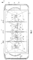
- the centrifugal fertilizer spreader according to FIG. 1 has the frame 1 and the storage container 2. On the front of the frame 1, the three-point coupling elements 3 are arranged, via which the centrifugal fertilizer spreader is to be coupled to the three-point linkage, not shown, of an agricultural tractor.
- the reservoir 2 is in its lower area in the four funnel tips 4, 5, 6 and 7 divided. Each funnel tip 4 to 7 is closed by means of a base plate 8, in each of which the outlet opening 9 is located.
- An adjustable slide is arranged below the base plate 9, by means of which the outlet opening 9 can be closed and its opening width adjusted.
- centrifugal disks 11, 12, 13 and 14 are each arranged on a transmission output shaft 15 of the transmissions 16, 17, 18 and 19. These gears are arranged on the frame 1.
- the throwing elements 20 are arranged on the centrifugal disks 11 to 14.
- the throwing elements 20 on the two centrifugal discs 11 and 14 have a greater length than the throwing elements 20 on the centrifugal discs 12 and 13.
- the fertilizer particles located in the storage container 2 are fed to the centrifugal disks 11 to 15 via the metering elements 10.
- the fertilizer particles are thrown off by the throwing blades 20 of the centrifugal disks 11 to 14 over an area which substantially exceeds the overall width of the entire centrifugal fertilizer spreader.
- the spreading width of the fertilizer spreader can be changed, with the centrifugal disks 11 to 14 with the throwing elements 20 distributing the fertilizer particles in a uniform spreading pattern over the soil surface to be sprinkled, in gaps that laterally adjoin and overlap.
- the two outer centrifugal disks 11 and 14 produce spreading fans, which extend from the spreader and seen in the direction of travel essentially into the width to the side of the centrifugal fertilizer spreader, while the spreading fans produced by the two other centrifugal disks 12 and 13 seen from the spreader and in relation to the direction of travel extend essentially to the rear and in width.
- the centrifugal disks 11 to 14 are offset from the line 22 running at right angles to the direction of travel 21.
- the line 22 runs through the axes of rotation 17 and 18 of the two inner centrifugal disks 12 and 13.
- the centrifugal disk drive shafts 16 and 19 of the outer centrifugal disks 11 and 14 are offset from the line 12 with respect to the direction of travel and are arranged forward.
- the dashed lines 23 indicate the outer flight circles of the outer parts of the longer throwing blades 20.
- the storage container 2 is divided into the outlet funnels 4 to 7 in its lower region.
- the number of discharge hoppers corresponds to the number of centrifugal disks 11 to 15.
- the metering elements, which are formed by the discharge openings 9 in connection with the slides, lie on a line 24 running at right angles to the direction of travel 21.
- the centrifugal disks 11 to 15 are driven via an articulated shaft, not shown, which is connected to the input shaft 25 of the central transmission 26, and via the shaft train formed by the shafts 27, 28, 29 and 30.
- a propeller shaft 33 is arranged between the gear 31 and 32, and the propeller shaft 36 is arranged between the gear 34 and the gear 35.
- the outer centrifugal discs 11 and 14 are slidably arranged on the frame 1 of the centrifugal fertilizer spreader.
- the bearing housing 37 of the outer centrifugal disks 11 and 14 are displaceable with respect to that with a sliding guide 38 Frame 1 and the metering device of the centrifugal fertilizer spreader arranged. Due to this sliding guide 38, the bearing housing 37 can be moved laterally outwards with the centrifugal disks 11 or 14. As a result, the application areas of the fertilizer on the centrifugal discs 11 and 14 are shifted.
- the adjusting device 39 is provided between the sliding guide 38 and the bearing housing 37, by means of which the bearing housing 37 can be set in a precisely defined manner in the sliding guide 38.
- the sliding guide 38 is fastened to a swivel arm 40 by means of the joint 41 on the frame 1.
- a further adjusting device 42 is provided between the swivel arm 40 and the frame 1, by means of which the swivel arm 40 and thus the sliding guide 38 can be adjusted to different positions relative to the frame 1 and to the respective metering device. This makes it possible for the application area of the fertilizer on the centrifugal disk 11 or 14 to be set precisely in each case. Scatter image correction can thus be carried out in a simple manner. It is possible to make the adjusting device 39 or 42 adjustable by means of a remote control device from the tractor seat.
- the sliding guide 38 is designed such that the gear housing 37 in the sliding guide 38 can be moved so far that when the centrifugal disks are moved for the purpose of turning off the centrifugal fertilizer spreader (calibration process), the two parts 36 and 36 '' of the telescopic shaft 36 are disengaged come as this Fig. 4 shows.
- the guide device 43 and 44 arranged on the outside of the centrifugal disc 14 is also displaced at the same time.
- the guide device 43 and 44 is arranged such that it is adjusted and moved simultaneously with the centrifugal discs 14.
- the sliding guide 38 has a length such that the centrifugal disc 14 can be pushed away completely below the metering device 9, as can be seen in FIG. 4.
- the reservoir 46 is divided into the two funnel tips 47 and 48 in its lower region.
- Each funnel tip 47 and 48 is closed by means of a base plate 49, in which there is an outlet opening.
- the outlet opening 9 and the slide arranged below it form the metering device 50.
- the centrifugal discs 51 and 52 are driven in opposite directions of rotation via the gear 54 . Throwing blades 53 of different lengths are arranged on each centrifugal disc 51 and 52.
- the fertilizers in the reservoir 46 are fed to the centrifugal disks 51 and 52 in adjustable amounts via the metering members 50.
- the fertilizer particles are thrown off by the throwing blades 53 of the centrifugal disks 51 and 52 over a region which substantially exceeds the overall width of the entire centrifugal fertilizer spreader.
- the gear housing 55 and 56 of the gear 54 are on Frame 45 each slidably arranged in a sliding guide 57.
- the centrifugal disks 51 and 52 can be adjusted within the sliding guide 57 by moving the gear housings 58 and 56 in the sliding guide 57 and can be adjusted in different positions. In this way, the application point of the fertilizer on the respective centrifugal disc can be changed.
- the sliding guides 57 are designed such that the centrifugal disks 52 and 51 can be pushed away completely below the metering device 50. This is indicated in Fig. 6 with the dash-dotted lines 52 'and 51'.
- a clutch 59 is arranged in the drive train for driving the centrifugal disks 51 and 52.
- This clutch 59 allows the slinger to be displaced in small areas without the clutch disengaging if the slinger is moved within small limits for the purpose of shifting the application area of the fertilizer on the slinger.
- the centrifugal discs can be easily moved in fine steps or continuously within the sliding guide for the purpose of shifting the application areas of the fertilizer on the centrifugal disc. Furthermore, due to the arrangement in a sliding guide, the centrifugal disks can be easily moved outwards into a twist-off position. This will automatically the drive is uncoupled.
- the collecting container can thus also be arranged very simply below the metering device. Furthermore, the respective centrifugal disc can be exchanged very easily, if this is desired, when the centrifugal disc is in the external position, ie in the calibration position.
Landscapes
- Life Sciences & Earth Sciences (AREA)
- Soil Sciences (AREA)
- Environmental Sciences (AREA)
- Fertilizing (AREA)
Applications Claiming Priority (2)
| Application Number | Priority Date | Filing Date | Title |
|---|---|---|---|
| DE4036235A DE4036235A1 (de) | 1990-11-14 | 1990-11-14 | Schleuderduengerstreuer |
| DE4036235 | 1990-11-14 |
Publications (3)
| Publication Number | Publication Date |
|---|---|
| EP0485898A2 true EP0485898A2 (fr) | 1992-05-20 |
| EP0485898A3 EP0485898A3 (en) | 1992-07-29 |
| EP0485898B1 EP0485898B1 (fr) | 1995-03-01 |
Family
ID=6418234
Family Applications (1)
| Application Number | Title | Priority Date | Filing Date |
|---|---|---|---|
| EP91119048A Expired - Lifetime EP0485898B1 (fr) | 1990-11-14 | 1991-11-08 | Epandeur centrifuge |
Country Status (2)
| Country | Link |
|---|---|
| EP (1) | EP0485898B1 (fr) |
| DE (2) | DE4036235A1 (fr) |
Cited By (3)
| Publication number | Priority date | Publication date | Assignee | Title |
|---|---|---|---|---|
| FR2768014A1 (fr) * | 1997-09-11 | 1999-03-12 | Rauch Landmaschfab Gmbh | Epandeur a deux disques a cadre de protection |
| FR2789260A1 (fr) | 1999-02-09 | 2000-08-11 | Rauch Landmaschfab Gmbh | Epandeur centrifuge a arbres d'entrainement montes chacun sur une console mobile |
| FR2790185A1 (fr) | 1999-02-25 | 2000-09-01 | Rauch Landmaschfab Gmbh | Epandeur centrifuge a point d'alimentation deplacable sur chacun des disques ejecteurs |
Family Cites Families (8)
| Publication number | Priority date | Publication date | Assignee | Title |
|---|---|---|---|---|
| US3017189A (en) * | 1960-04-08 | 1962-01-16 | Belt Corp | Power-driven spreader apparatus for fertilizer or the like |
| FR1400911A (fr) * | 1964-07-10 | 1965-05-28 | Amazonen Werke H Dreyer Fa | Dispositif d'épandage en lignes pour des épandeurs centrifuges |
| DE2041804A1 (de) * | 1970-08-22 | 1972-02-24 | Max Pietsch | Streuvorrichtung fuer veraenderliches Streubild |
| DE3377195D1 (en) * | 1982-01-21 | 1988-08-04 | Kuhn Sa | Manure spreader |
| DE3310694A1 (de) * | 1983-03-24 | 1984-09-27 | Amazonen Werke Dreyer H | Schleuderstreuer, insbesondere zur ausbringung von mineralischen streustoffen |
| DE3604954A1 (de) * | 1986-02-17 | 1987-08-20 | Heinz Dr Aeissen | Verfahren zum ausstreuen von mineralischem streugut mit einem duengerstreuer und zur durchfuehrung des verfahrens geeigneter duengerstreuer |
| DE8705460U1 (de) * | 1987-04-11 | 1987-07-02 | Accord-Landmaschinen Heinrich Weiste & Co Gmbh, 4770 Soest | Düngerstreuer |
| DE4101681A1 (de) * | 1991-01-22 | 1991-06-20 | Rauch Landmaschfab Gmbh | Schleuderstreuer |
-
1990
- 1990-11-14 DE DE4036235A patent/DE4036235A1/de not_active Withdrawn
-
1991
- 1991-11-08 DE DE59104770T patent/DE59104770D1/de not_active Expired - Fee Related
- 1991-11-08 EP EP91119048A patent/EP0485898B1/fr not_active Expired - Lifetime
Cited By (3)
| Publication number | Priority date | Publication date | Assignee | Title |
|---|---|---|---|---|
| FR2768014A1 (fr) * | 1997-09-11 | 1999-03-12 | Rauch Landmaschfab Gmbh | Epandeur a deux disques a cadre de protection |
| FR2789260A1 (fr) | 1999-02-09 | 2000-08-11 | Rauch Landmaschfab Gmbh | Epandeur centrifuge a arbres d'entrainement montes chacun sur une console mobile |
| FR2790185A1 (fr) | 1999-02-25 | 2000-09-01 | Rauch Landmaschfab Gmbh | Epandeur centrifuge a point d'alimentation deplacable sur chacun des disques ejecteurs |
Also Published As
| Publication number | Publication date |
|---|---|
| EP0485898A3 (en) | 1992-07-29 |
| DE4036235A1 (de) | 1992-05-21 |
| DE59104770D1 (de) | 1995-04-06 |
| EP0485898B1 (fr) | 1995-03-01 |
Similar Documents
| Publication | Publication Date | Title |
|---|---|---|
| EP0540889B1 (fr) | Epandeur d'engrais centrifuge | |
| EP0820219B1 (fr) | Epandeur d'engrais centrifuge | |
| DE4134315A1 (de) | Schleuderduengerstreuer | |
| EP0485898B1 (fr) | Epandeur centrifuge | |
| EP0968639B1 (fr) | Epandeur centrifuge pour engrais | |
| EP0433562A2 (fr) | Epandeur d'engrais centrifuge | |
| DE8817236U1 (de) | Ausbring- und Verteilsystem | |
| EP0809427B1 (fr) | Epandeur centrifuge pour engrais | |
| DE3739265A1 (de) | Schleuderstreuer | |
| DE4003945C2 (de) | Schleuderdüngerstreuer | |
| EP0292874A2 (fr) | Distributeur à grand tonnage | |
| DE3310694A1 (de) | Schleuderstreuer, insbesondere zur ausbringung von mineralischen streustoffen | |
| EP0405180A2 (fr) | Epandeur d'engrais | |
| DE19606586A1 (de) | Schleuderdüngerstreuer | |
| DE4302802A1 (de) | Schleuderdüngerstreuer | |
| DE3901523A1 (de) | Schleuderduengerstreuer | |
| EP0485899A2 (fr) | Epandeur centrifuge | |
| DE3615818A1 (de) | Verteilmaschine | |
| DD297905A5 (de) | Schleuderduengerstreuer | |
| EP1190615A2 (fr) | Epandeur centrifuge pour engrais | |
| EP0461486B1 (fr) | Epandeur | |
| DE19828713A1 (de) | Zentrifugaldüngerstreuer | |
| DE4102986A1 (de) | Schleuderduengerstreuer | |
| DE3533585A1 (de) | Dreipunktanbaumaschine zum ausbringen von koernigem material | |
| EP0410109A1 (fr) | Epandeur centrifuge pour matériau coulant, en particulier engrais |
Legal Events
| Date | Code | Title | Description |
|---|---|---|---|
| PUAI | Public reference made under article 153(3) epc to a published international application that has entered the european phase |
Free format text: ORIGINAL CODE: 0009012 |
|
| AK | Designated contracting states |
Kind code of ref document: A2 Designated state(s): DE FR GB NL |
|
| PUAL | Search report despatched |
Free format text: ORIGINAL CODE: 0009013 |
|
| AK | Designated contracting states |
Kind code of ref document: A3 Designated state(s): DE FR GB NL |
|
| 17P | Request for examination filed |
Effective date: 19921219 |
|
| 17Q | First examination report despatched |
Effective date: 19940321 |
|
| GRAA | (expected) grant |
Free format text: ORIGINAL CODE: 0009210 |
|
| AK | Designated contracting states |
Kind code of ref document: B1 Designated state(s): DE FR GB NL |
|
| PG25 | Lapsed in a contracting state [announced via postgrant information from national office to epo] |
Ref country code: NL Free format text: LAPSE BECAUSE OF NON-PAYMENT OF DUE FEES Effective date: 19950301 Ref country code: GB Effective date: 19950301 |
|
| ET | Fr: translation filed | ||
| REF | Corresponds to: |
Ref document number: 59104770 Country of ref document: DE Date of ref document: 19950406 |
|
| NLV1 | Nl: lapsed or annulled due to failure to fulfill the requirements of art. 29p and 29m of the patents act | ||
| GBV | Gb: ep patent (uk) treated as always having been void in accordance with gb section 77(7)/1977 [no translation filed] |
Effective date: 19950301 |
|
| PLBQ | Unpublished change to opponent data |
Free format text: ORIGINAL CODE: EPIDOS OPPO |
|
| PLBI | Opposition filed |
Free format text: ORIGINAL CODE: 0009260 |
|
| PLBF | Reply of patent proprietor to notice(s) of opposition |
Free format text: ORIGINAL CODE: EPIDOS OBSO |
|
| 26 | Opposition filed |
Opponent name: RAUCH LANDMASCHINENFABRIK GMBH Effective date: 19951130 |
|
| PLBF | Reply of patent proprietor to notice(s) of opposition |
Free format text: ORIGINAL CODE: EPIDOS OBSO |
|
| PLBO | Opposition rejected |
Free format text: ORIGINAL CODE: EPIDOS REJO |
|
| PLBN | Opposition rejected |
Free format text: ORIGINAL CODE: 0009273 |
|
| STAA | Information on the status of an ep patent application or granted ep patent |
Free format text: STATUS: OPPOSITION REJECTED |
|
| 27O | Opposition rejected |
Effective date: 19970411 |
|
| PGFP | Annual fee paid to national office [announced via postgrant information from national office to epo] |
Ref country code: DE Payment date: 19971118 Year of fee payment: 7 |
|
| PGFP | Annual fee paid to national office [announced via postgrant information from national office to epo] |
Ref country code: FR Payment date: 19971128 Year of fee payment: 7 |
|
| PG25 | Lapsed in a contracting state [announced via postgrant information from national office to epo] |
Ref country code: FR Free format text: LAPSE BECAUSE OF NON-PAYMENT OF DUE FEES Effective date: 19990730 |
|
| REG | Reference to a national code |
Ref country code: FR Ref legal event code: ST |
|
| PG25 | Lapsed in a contracting state [announced via postgrant information from national office to epo] |
Ref country code: DE Free format text: LAPSE BECAUSE OF NON-PAYMENT OF DUE FEES Effective date: 19990901 |