EP0485902A1 - Dispositif de guidage de barres auto-centrant - Google Patents
Dispositif de guidage de barres auto-centrant Download PDFInfo
- Publication number
- EP0485902A1 EP0485902A1 EP91119068A EP91119068A EP0485902A1 EP 0485902 A1 EP0485902 A1 EP 0485902A1 EP 91119068 A EP91119068 A EP 91119068A EP 91119068 A EP91119068 A EP 91119068A EP 0485902 A1 EP0485902 A1 EP 0485902A1
- Authority
- EP
- European Patent Office
- Prior art keywords
- jaws
- guide
- bars
- guide device
- bar
- Prior art date
- Legal status (The legal status is an assumption and is not a legal conclusion. Google has not performed a legal analysis and makes no representation as to the accuracy of the status listed.)
- Withdrawn
Links
- 230000005540 biological transmission Effects 0.000 description 2
- 230000000694 effects Effects 0.000 description 2
- 230000000712 assembly Effects 0.000 description 1
- 238000000429 assembly Methods 0.000 description 1
- 238000006243 chemical reaction Methods 0.000 description 1
- 230000001419 dependent effect Effects 0.000 description 1
- 238000006073 displacement reaction Methods 0.000 description 1
- 230000007246 mechanism Effects 0.000 description 1
- 230000000153 supplemental effect Effects 0.000 description 1
Images


Classifications
-
- B—PERFORMING OPERATIONS; TRANSPORTING
- B23—MACHINE TOOLS; METAL-WORKING NOT OTHERWISE PROVIDED FOR
- B23B—TURNING; BORING
- B23B13/00—Arrangements for automatically conveying or chucking or guiding stock
- B23B13/12—Accessories, e.g. stops, grippers
- B23B13/123—Grippers, pushers or guiding tubes
-
- B—PERFORMING OPERATIONS; TRANSPORTING
- B23—MACHINE TOOLS; METAL-WORKING NOT OTHERWISE PROVIDED FOR
- B23B—TURNING; BORING
- B23B31/00—Chucks; Expansion mandrels; Adaptations thereof for remote control
- B23B31/02—Chucks
- B23B31/10—Chucks characterised by the retaining or gripping devices or their immediate operating means
- B23B31/12—Chucks with simultaneously-acting jaws, whether or not also individually adjustable
- B23B31/1261—Chucks with simultaneously-acting jaws, whether or not also individually adjustable pivotally movable in a radial plane
- B23B31/1276—Chucks with simultaneously-acting jaws, whether or not also individually adjustable pivotally movable in a radial plane using fluid-pressure means to actuate the gripping means
Definitions
- the present invention relates to a bar guide device for feeding circular or polygonal bars to the spindle of a machine tool, such as a lathe or the like, in which the bars are guided by a set of adjacent guide jaws, having semicircular guide surfaces parallely arranged to the longitudinal axis of the spindle, in order to support and guide the bars to be fed, and in which the jaws are pivotable and reciprocally movable to allow a self-centering action and a guide effect for bars having different cross-sectional dimensions.
- a device for guiding bars of the type cited above, is known for example from EP-A- 0384344 of the same applicant comprising two opposite groups of guide jaws which can be reciprocated between closed and an open conditions, and in which the jaws have semicircular bar guide surfaces, and in which the jaws of one group are intercalated or staggered in relation to the jaws of the other group, and control means to inwardly and downwardly reciprocate one group of jaws to and from the other so as to maintain the guide surfaces coaxially arranged to the bar to adapt each time the jaws disposition to guide bars of different diameters or different dimensions.
- This bar guide device is particular suitable for guiding bars which are medium or small in diameter, as well as bars or cut down sizes of bars having relatively low in weight, since guiding and supporting the bars by two superimposed jaws groups does not allow high rotation speeds to be reached, or bars of considerable weight to be suitably guided and supported during rotation causing noise and vibrations; the use of supplemental centering means is therefore suggested to prevent lateral movement of the bars at both ends.
- an extremely complex control system for the jaws is proposed, which is difficult to adapt in order to form guide systems which require a different arrangement or function of the jaws for guiding and sliding bars of different cross-sectional dimensions and lenght.
- the object of the present invention is to provide a self-centering guide device for supporting and feeding bars to a spindle of a machine tool, which is simple in constructional and at the same time adopts jaws which can be angularly positioned to allow bars of different dimensions or different diameters to be properly supported and guided, without causing vibrations and noise during rotation.
- a further object of the invention is to provide a guide device as related above, which also enables bars of large dimensions to be supported and guided, holding them in two or more circumferentially spaced positions, still maintaining the advantageous self-centering characteristics of the bar-guide device mentioned above.
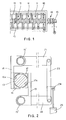
- FIG. 1 shows the end portion of a generical bar feeder comprising a guide device according to the present invention.
- the feeder in general comprises a frame 10 provided with one or more guide units 11 for supporting and axially guiding a bar 13 towards the spindle of a machine tool, not shown, and also comprises an external guide unit 14 at the end of the frame 10 which is turned towards the machine tool.
- the bar guide device or each guide unit 11 of the guide device may comprise two or more adjacent and parallely arranged guide jaws 16, 17 having semicircular guide surfaces 16a, 17a which are peripherally arranged around a portion of the bar 13 to be fed and which restrain it circumferentially so as to allow it to rotate and to slide freely.
- the semicircular guide surface 16a, 17a in each jaw of the device may extend for an arc of a circle whatsoever which is equal to or smaller than 180°, whose radius may in any case be chosen and which, as a general rule, must correspond to or be greater than the radius of the maximum diameter of the bars to be fed as intended for that specific device.
- the guide device or each guide unit 11 of the device may comprise an even or uneven number of guide jaws, juxtapposed and parallely adjacent to each other which are angularly spaced so as to surround the outline of the bar, or a multiple of this number, maintaining a circumferential arrangement of the pivotal axes of the jaws in each individual group, or of the entire device, along a circle concentric to the axis of the spindle of the machine tool.
- the rotational or pivotal axes of the jaws preferably should be angularly spaced apart for a distance equal or corresponding to that of the jaws, that is to the contact points with the bar.
- the pivotal axis of each individual jaw may assume any angular arrangement whatsoever in relation to the jaw itself, provided that it is situated on a circle whose radius is greater than that of the semicircular guide surfaces for each individual jaw.
- the pivotal axis of the jaw or of each jaw of the guide unit is preferably positioned in a plane which passes through the spindle axis (which coincides with the sliding axis of the bar to be fed) and which is orthogonal to the plane passing through said sliding axis of the abovementioned bar and the intermediate contact point between the circular guide surface of the jaw, for the bars of maximum diameter to be fed.
- the positioning of each unit of jaws may remain unchanged or be identical, or else a unit of jaws may be differently positioned in an angular direction, in relation to a unit or adjacent units of the guide device.
- the self-centering action to maintain the coaxiality of the axes of the guide device and of the machine tool spindle is ensured by the thrusts or the forces exerted by the individual jaws, of the device or of each unit of the device, which are always oriented towards a common centre which coincides with the sliding axis of the bar; in this way the thrust effects or the reactions of the jaws, whatever their angular position or operative condition may be, are compensated as a function of the diameter or cross-width dimensions of the bars to be fed.
- Figures 2, 3 and 4 show a first solution of the guide device according to the invention, particularly suitable for the external guide unit 14 of the feeder.
- the guide assembly in figure 2 in its simplest form, is basically composed of two opposite jaws 16 and 17 having semicircular guide surfaces 16a and 17a whose radius of curvature corresponds to the maximum radius of the bars 13 to be fed, or to the maximum circle in which the cross-width section of a polygonal bar may be inscribed.
- the guide jaws 16, 17 are parallely arranged adjacent to each other, in differant planes, and are partially overlapping, as shown in figures 2 and 3 where, merely by way of an example, three pairs of guide jaws 16 and 17 are shown adjacent to each other in a guide unit.
- the guide jaws 16 which are on one side of the bar 13 are connected to respective pivotal arms 18 in order to rotate together with a rotational shaft provided by a tubular element 15' and likewise the other jaws 17, opposite the previous ones, are attached to respective pivotal arms 19 connected in order to rotate with a second shaft which is also composed of a tubular element 15'' supported with the former one in a rotary manner by the structure 10 of the feeder.
- the axes of the two rotational shafts 15' and 15'' are arranged along a circle which is concentric with sliding axis of the bar 13 which in turn must always coincide with the axis of the machine tool spindle; moreover these shafts 15', 15'' are on opposite sides of the jaws 16, 17 so that their axes lie in a plane passing through the sliding axis of the bars.
- the angular spacing of the rotational shafts 15' and 15'' of the jaws 16 and 17 is of utmost importance since it preferably must coincide with the same angular spacing between the cross plane of symmetry of the jaws in order to maintain the sliding axis of the bars 13 constantly centred in the same position in relation to the spindle of the machine tool, independently of the diameter of the bars 13; in fact a different angular disposition between the shafts 15' and 15'' would lead to dissymmetry of the contact points of the bar with the jaws and hence to a possible lateral displacement of the sliding axis thus causing the bars to become disaligned.
- control means have been provided to actuate jointly both jaws in each unit or both sets of jaws which compose guide device, by means of which a simultaneous clockwise and/or counterclockwise rotation of all jaws or of each set of jaws of the guide units is brought about in the same angular direction, to move said jaws between an open position and differant closed positions in relation to the cross-sectional dimensions of the bars.
- control means may however be composed of and may use any source of power, be it hydraulic, pneumatic, electric or combinations of these.
- the arms 18 and 19 of the jaws, or the rotation shafts 15' and 15'' are integral with two lever arms 21 and 22 which extend on the one same side of the jaws, and which are jointed to an intermediate link rod 23; the link rod 23 in one of its intermediate point is linked at 24 to the end of a rod of a drive cylinder 25 or another suitable linear actuator.
- any other drive means could be provided, for example using gear wheels or sector gear, interconnected to rotate with the shafts 15' and 15'' again driven by a hydraulic or pneumatic cylinder, or a suitable drive motor; the gear wheels or sector gears engage with each other directly or indirectly by an appropriate kinematic transmission, or by means of chains, belts, cogged belts etc.
- the device in figure 2 comprises a pair of opposite and staggered guide jaws 16, 17 which could be doubled or multiplied for the required number of times in order to obtain the necessary guide length. This solution is to be preferred as being suitable for use as an external guide 14 on two sides of the bars.
- the difference between the device in figure 2 and that in figure 5 mainly consists in the use of four jaw unit, or a multiple of four jaws, in each unit, in place of two, with pairs of opposite jaws, arranged in orthogonal directions, so as to provide a larger guide surface which is approaching to a circular guide surface, even for smaller diameters of the bars.
- greater bar guiding stability is achieved also for bars of larger dimensions which may therefore be made to rotate at a higher number of revolutions without causing vibrations and excessive noise.
- the rotational shafts of the jaws are arranged pairs of opposed shafts, in orthogonal planes again passing through the sliding axis of the bars, or having angular spacing which are similar to those of the guide jaws.
- the position of the rotational shafts and their distance from the jaws may be such as to make these shafts perform the additional function of stopping means for the jaws in the condition of maximum opening of figure 8, to insert or load a new bar to be fed; since the overall dimensions of the jaws may not allow bars with a large diameter of transverse dimensions to be inserted, the rotational shafts can be further spaced away, maintaining their symmetrical arrangement as related previously, in order to enable the jaws to rotate beyond the shafts, in this case increasing the width of the lateral opening for inserting the bars.
- the guide device in figures 5-8 comprises four jaws 26, 27, 28 and 29 which are completely identical to the jaws of the previous example, adjacent and arranged in staggered planes, parallel to each other. More particularly, the jaws 26 and 28 are arranged on two opposite sides in relation to the bar 30, while jaws 27 and 29 are opposite each other on the sides lying in a plane orthogonal to the previous one.
- the jaws 26 and 28 are connected by means of arms 31 and 32 to respective rotational shafts 33 and 34 whose longitudinal axes lie in the same plane which passes through the sliding axis of the bar 30, while the remaining two jaws 27 and 29 are connected by arms 35 and 36 to respective rotational shafts 37 and 38 whose axes lie in a plane which again passes through the sliding axis of the bar 30 but is arranged orthogonally to the plane of the shafts 33 and 34 mentioned previously.
- the guide device is also provided with control means which enable all the jaws to rotate or reciprocate simultaneously in opposite directions so as to close or open the jaws fully, forming a lateral opening (Fig.
- the control means comprises a set of sector gears 40, 41, 42a, 42b, 43 and 44, rotatably connected to shafts denoted respectively by 37, 33, 38 and 34; the sector gears engage in pairs reciprocally so as to cause the simultaneous rotation of pair of jaws of the unit alternately in opposite directions.
- a control means 46 such as a pneumatic cylinder, hydraulic cylinder, a linear actuator or other suitable drive means.
- gear wheels or kinematic or lever mechanisms of another kind could be used, comprising chain or belt transmissions or the like, provided that they are suited to causing the simultaneous or reciprocal rotation of the various jaws in the unit.
- guide units composed of two and four jaw sets respectively, or their multiples; nevertheless, as stated previously, guide units can also be constructed which use an uneven number of jaws, or a multiple of them, for example three jaws angularly spaced apart by 120° and staggered in relation to each other according to the general principles of the present invention. This is shown by way of an example in figure 9.
Landscapes
- Engineering & Computer Science (AREA)
- Mechanical Engineering (AREA)
- Turning (AREA)
- Attitude Control For Articles On Conveyors (AREA)
Applications Claiming Priority (2)
| Application Number | Priority Date | Filing Date | Title |
|---|---|---|---|
| IT02201890A IT1245821B (it) | 1990-11-12 | 1990-11-12 | Dispositivo di guida autocentrante per alimentatori di barre |
| IT2201890 | 1990-11-12 |
Publications (1)
| Publication Number | Publication Date |
|---|---|
| EP0485902A1 true EP0485902A1 (fr) | 1992-05-20 |
Family
ID=11190273
Family Applications (1)
| Application Number | Title | Priority Date | Filing Date |
|---|---|---|---|
| EP91119068A Withdrawn EP0485902A1 (fr) | 1990-11-12 | 1991-11-08 | Dispositif de guidage de barres auto-centrant |
Country Status (2)
| Country | Link |
|---|---|
| EP (1) | EP0485902A1 (fr) |
| IT (1) | IT1245821B (fr) |
Cited By (7)
| Publication number | Priority date | Publication date | Assignee | Title |
|---|---|---|---|---|
| EP0689890A1 (fr) | 1994-06-07 | 1996-01-03 | CUCCHI GIOVANNI & C. S.r.l. | Dispositif angulairement pivotable à centrage automatique pour supporter des barres en rotation |
| EP0850714A1 (fr) * | 1996-12-23 | 1998-07-01 | PIETRO CUCCHI S.p.A. | Dispositif de centrage de barre pour un embarreur de tour automatique |
| WO2008089915A1 (fr) * | 2007-01-22 | 2008-07-31 | Kurt Breuning Irco-Maschinenbau Gmbh | Dispositif pour acheminer des barres de matériau à une machine-outil |
| IT201900008016A1 (it) | 2019-06-04 | 2020-12-04 | Cucchi Giovanni & C Srl | Dispositivo-centratore per l'alimentazione di barre a macchine utensili |
| IT202000023320A1 (it) | 2020-10-02 | 2022-04-02 | Cucchi Giovanni & C Srl | Dispositivo autocentrante per il supporto e la guida di barre |
| IT202000023326A1 (it) | 2020-10-02 | 2022-04-02 | Cucchi Giovanni & C Srl | Apparato per il centraggio, guida e avanzamento di barre da alimentare a macchine utensili |
| EP4464440A1 (fr) | 2023-05-17 | 2024-11-20 | LNS Management Sàrl | Dispositif de guidage pour ravitailleur de barres |
Citations (6)
| Publication number | Priority date | Publication date | Assignee | Title |
|---|---|---|---|---|
| CH121387A (de) * | 1926-09-15 | 1927-07-01 | Meier Ernst | Selbstzentrierendes Aufspannfutter. |
| GB356917A (en) * | 1929-08-24 | 1931-09-17 | Hermann Hahn | Improvements in or relating to turning lathes |
| US4058036A (en) * | 1976-07-09 | 1977-11-15 | Richard Arnold Austin | Adjustable spindle liner tube or filler tube |
| FR2437903A1 (fr) * | 1978-10-05 | 1980-04-30 | Cucchi Pietro Sdf | Chargeur d'alimentation automatique de tours automatiques a mandrins multiples |
| EP0384344A2 (fr) * | 1989-02-22 | 1990-08-29 | CUCCHI GIOVANNI & C. S.r.l. | Dispositif d'avance barre pour machine outil |
| US4967579A (en) * | 1989-10-03 | 1990-11-06 | Italimpianti Of America, Inc. | Adjustable guide for rotating cylindrical member |
-
1990
- 1990-11-12 IT IT02201890A patent/IT1245821B/it active IP Right Grant
-
1991
- 1991-11-08 EP EP91119068A patent/EP0485902A1/fr not_active Withdrawn
Patent Citations (6)
| Publication number | Priority date | Publication date | Assignee | Title |
|---|---|---|---|---|
| CH121387A (de) * | 1926-09-15 | 1927-07-01 | Meier Ernst | Selbstzentrierendes Aufspannfutter. |
| GB356917A (en) * | 1929-08-24 | 1931-09-17 | Hermann Hahn | Improvements in or relating to turning lathes |
| US4058036A (en) * | 1976-07-09 | 1977-11-15 | Richard Arnold Austin | Adjustable spindle liner tube or filler tube |
| FR2437903A1 (fr) * | 1978-10-05 | 1980-04-30 | Cucchi Pietro Sdf | Chargeur d'alimentation automatique de tours automatiques a mandrins multiples |
| EP0384344A2 (fr) * | 1989-02-22 | 1990-08-29 | CUCCHI GIOVANNI & C. S.r.l. | Dispositif d'avance barre pour machine outil |
| US4967579A (en) * | 1989-10-03 | 1990-11-06 | Italimpianti Of America, Inc. | Adjustable guide for rotating cylindrical member |
Cited By (8)
| Publication number | Priority date | Publication date | Assignee | Title |
|---|---|---|---|---|
| EP0689890A1 (fr) | 1994-06-07 | 1996-01-03 | CUCCHI GIOVANNI & C. S.r.l. | Dispositif angulairement pivotable à centrage automatique pour supporter des barres en rotation |
| EP0850714A1 (fr) * | 1996-12-23 | 1998-07-01 | PIETRO CUCCHI S.p.A. | Dispositif de centrage de barre pour un embarreur de tour automatique |
| WO2008089915A1 (fr) * | 2007-01-22 | 2008-07-31 | Kurt Breuning Irco-Maschinenbau Gmbh | Dispositif pour acheminer des barres de matériau à une machine-outil |
| IT201900008016A1 (it) | 2019-06-04 | 2020-12-04 | Cucchi Giovanni & C Srl | Dispositivo-centratore per l'alimentazione di barre a macchine utensili |
| US12202048B2 (en) | 2019-06-04 | 2025-01-21 | Cucchi Giovanni & C. S.R.L. | Centering device for supplying bars to machine tools |
| IT202000023320A1 (it) | 2020-10-02 | 2022-04-02 | Cucchi Giovanni & C Srl | Dispositivo autocentrante per il supporto e la guida di barre |
| IT202000023326A1 (it) | 2020-10-02 | 2022-04-02 | Cucchi Giovanni & C Srl | Apparato per il centraggio, guida e avanzamento di barre da alimentare a macchine utensili |
| EP4464440A1 (fr) | 2023-05-17 | 2024-11-20 | LNS Management Sàrl | Dispositif de guidage pour ravitailleur de barres |
Also Published As
| Publication number | Publication date |
|---|---|
| IT1245821B (it) | 1994-10-24 |
| IT9022018A1 (it) | 1992-05-12 |
| IT9022018A0 (it) | 1990-11-12 |
Similar Documents
| Publication | Publication Date | Title |
|---|---|---|
| EP0485902A1 (fr) | Dispositif de guidage de barres auto-centrant | |
| EP2762426A1 (fr) | Dispositif pour retourner et transporter un objet | |
| EP3339222B1 (fr) | Dispositif de transport pour ébauches de boîte | |
| US3955772A (en) | Unwinding apparatus | |
| US4422543A (en) | Universal conveyor | |
| DE2558802A1 (de) | Vorrichtung zum umleiten der in querrichtung ausgerichteten aufeinanderfolgenden zigaretten in anlagen fuer die direkte beschickung von zigaretten, welche mit einer vorrichtung zum ausgleichen der produktionsschwankungen zwischen herstellungsmaschinen und verpackungsmaschine versehen sind | |
| DE19506721A1 (de) | Rohrbiegeeinrichtung | |
| GB2131375A (en) | Machine for effecting the transfer of objects in the space between positions having predetermined co-ordinates | |
| US5924918A (en) | Device for processing poultry bodies | |
| EP0172752B1 (fr) | Appareil pour étirer un matériau plastique | |
| GB2215006A (en) | Drive chain | |
| DE3907130A1 (de) | Stufenlos regelbares flachriemenuebersetzungsgetriebe mit einer die drehmomentuebertragung erhoehenden komponente | |
| US4561536A (en) | Rotary conveyor apparatus | |
| WO1997029872A1 (fr) | Appareil de dressage | |
| EP0839746B1 (fr) | Dispositif pour convoyer des feuilles | |
| JP2665411B2 (ja) | スピンドル同時回転装置 | |
| DE2356071C3 (de) | Vorrichtung zur Außenbearbeitung von Grafit-, Farb-, Kosmetikstiften o.dgl. | |
| EP1035354A2 (fr) | Dispositif de traction par chaines pour étirage | |
| EP0448699A1 (fr) | Mecanisme d'entrainement pas a pas. | |
| US4333308A (en) | False-twist system switchable between S-twist and Z-twist | |
| CN120155476B (zh) | 一种金属棒材加工装置 | |
| DE3415584A1 (de) | Kettenantrieb mit abtriebsseitiger periodischer ruhezeit | |
| CN120901528B (zh) | 一种体育器材加工用激光切割设备 | |
| DE62963C (de) | Als Wechsel- und Wendegetriebe wirkendes Schnurlauf-Differentialgetriebe | |
| EP2605221A1 (fr) | Dispositif destiné à la manipulation de récipients avec une installation de roulement |
Legal Events
| Date | Code | Title | Description |
|---|---|---|---|
| PUAI | Public reference made under article 153(3) epc to a published international application that has entered the european phase |
Free format text: ORIGINAL CODE: 0009012 |
|
| AK | Designated contracting states |
Kind code of ref document: A1 Designated state(s): DE FR GB SE |
|
| STAA | Information on the status of an ep patent application or granted ep patent |
Free format text: STATUS: THE APPLICATION IS DEEMED TO BE WITHDRAWN |
|
| 18D | Application deemed to be withdrawn |
Effective date: 19921121 |