EP0485920A1 - Elektrisches Kabel mit hoher Übertragungsgeschwindigkeit - Google Patents
Elektrisches Kabel mit hoher Übertragungsgeschwindigkeit Download PDFInfo
- Publication number
- EP0485920A1 EP0485920A1 EP91119172A EP91119172A EP0485920A1 EP 0485920 A1 EP0485920 A1 EP 0485920A1 EP 91119172 A EP91119172 A EP 91119172A EP 91119172 A EP91119172 A EP 91119172A EP 0485920 A1 EP0485920 A1 EP 0485920A1
- Authority
- EP
- European Patent Office
- Prior art keywords
- conductors
- rod
- rods
- conductor
- insulating
- Prior art date
- Legal status (The legal status is an assumption and is not a legal conclusion. Google has not performed a legal analysis and makes no representation as to the accuracy of the status listed.)
- Granted
Links
- 239000004020 conductor Substances 0.000 claims abstract description 70
- 239000011295 pitch Substances 0.000 claims description 8
- 230000001681 protective effect Effects 0.000 abstract description 3
- 230000005540 biological transmission Effects 0.000 abstract description 2
- 229910000906 Bronze Inorganic materials 0.000 abstract 1
- 239000010974 bronze Substances 0.000 abstract 1
- KUNSUQLRTQLHQQ-UHFFFAOYSA-N copper tin Chemical compound [Cu].[Sn] KUNSUQLRTQLHQQ-UHFFFAOYSA-N 0.000 abstract 1
- -1 polyethylene Polymers 0.000 description 14
- 239000004698 Polyethylene Substances 0.000 description 9
- 229920000573 polyethylene Polymers 0.000 description 9
- 241000731961 Juncaceae Species 0.000 description 4
- 239000007787 solid Substances 0.000 description 4
- RYGMFSIKBFXOCR-UHFFFAOYSA-N Copper Chemical compound [Cu] RYGMFSIKBFXOCR-UHFFFAOYSA-N 0.000 description 2
- 241000735470 Juncus Species 0.000 description 2
- 239000003989 dielectric material Substances 0.000 description 2
- 238000006073 displacement reaction Methods 0.000 description 2
- 239000011810 insulating material Substances 0.000 description 2
- 230000002093 peripheral effect Effects 0.000 description 2
- 239000004743 Polypropylene Substances 0.000 description 1
- 240000008042 Zea mays Species 0.000 description 1
- 239000000956 alloy Substances 0.000 description 1
- 229910045601 alloy Inorganic materials 0.000 description 1
- 230000004075 alteration Effects 0.000 description 1
- 238000005452 bending Methods 0.000 description 1
- YFXPPSKYMBTNAV-UHFFFAOYSA-N bensultap Chemical compound C=1C=CC=CC=1S(=O)(=O)SCC(N(C)C)CSS(=O)(=O)C1=CC=CC=C1 YFXPPSKYMBTNAV-UHFFFAOYSA-N 0.000 description 1
- 229910052802 copper Inorganic materials 0.000 description 1
- 239000010949 copper Substances 0.000 description 1
- 238000000151 deposition Methods 0.000 description 1
- 230000000694 effects Effects 0.000 description 1
- 239000000463 material Substances 0.000 description 1
- 239000002184 metal Substances 0.000 description 1
- 229910052751 metal Inorganic materials 0.000 description 1
- 239000004033 plastic Substances 0.000 description 1
- 229920003023 plastic Polymers 0.000 description 1
- 229920000728 polyester Polymers 0.000 description 1
- 229920001155 polypropylene Polymers 0.000 description 1
- 229920001343 polytetrafluoroethylene Polymers 0.000 description 1
- 239000004810 polytetrafluoroethylene Substances 0.000 description 1
- 239000000843 powder Substances 0.000 description 1
Images


Classifications
-
- H—ELECTRICITY
- H01—ELECTRIC ELEMENTS
- H01B—CABLES; CONDUCTORS; INSULATORS; SELECTION OF MATERIALS FOR THEIR CONDUCTIVE, INSULATING OR DIELECTRIC PROPERTIES
- H01B11/00—Communication cables or conductors
- H01B11/002—Pair constructions
-
- H—ELECTRICITY
- H01—ELECTRIC ELEMENTS
- H01B—CABLES; CONDUCTORS; INSULATORS; SELECTION OF MATERIALS FOR THEIR CONDUCTIVE, INSULATING OR DIELECTRIC PROPERTIES
- H01B7/00—Insulated conductors or cables characterised by their form
- H01B7/02—Disposition of insulation
- H01B7/0233—Cables with a predominant gas dielectric
-
- H—ELECTRICITY
- H01—ELECTRIC ELEMENTS
- H01B—CABLES; CONDUCTORS; INSULATORS; SELECTION OF MATERIALS FOR THEIR CONDUCTIVE, INSULATING OR DIELECTRIC PROPERTIES
- H01B7/00—Insulated conductors or cables characterised by their form
- H01B7/02—Disposition of insulation
- H01B7/0241—Disposition of insulation comprising one or more helical wrapped layers of insulation
Definitions
- the invention relates to an electrical cable with high propagation speed, such as those used for transmitting data from one computer machine to another.
- To produce a cable having a high propagation speed it is known to reduce the linear capacity existing between two conductors of this cable, by increasing the distance between these conductors and the distance between these conductors and the screen; and by reducing the average value of the permittivity of the dielectrics located between these two conductors along the cable.
- This cable is bulky because the insulating core has a diameter much greater than the diameter of each of the 4 conductors. It maintains a predetermined distance between the conductors, so as to reduce the linear capacity between the conductors.
- the core and the first insulating layer may be made of polytetrafluoroethylene expanded.
- the object of the invention is to provide a cable having a high propagation speed, without having the disadvantages of cables of known types.
- the object of the invention is an electric cable with a high propagation speed comprising a plurality of conductors and means for maintaining a predetermined distance between said conductors; characterized in that two insulating rods enclosing two neighboring conductors rotate in the same direction and have the same constant pitch, and are nested, the rod enclosing a conductor also bears against the other conductor.
- the object of the invention is also a cable characterized in that two insulating rods enclosing two neighboring conductors rotate in opposite directions and have different pitches, not multiple from one another, so as never to be nest.
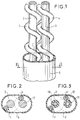
- the turns of rod 1 and rod 4 respectively enclose conductors 2 and 3.
- Each of rods 3 and 4 is made from a straight cylindrical rod with circular section which is wound around one of conductors 2 or 3.
- Each rod 1 and 4 therefore encloses one of the conductors in these turns.
- the two rods 1 and 4 are wound with the same pitch which is constant and which is much greater than the diameter of the section of each rod, so that the free volume between the turns is much greater than the volume occupied by the turns.
- the conductors 2 and 3, enclosed in the rods 1 and 4 are brought together by nesting the turns of the rods, so that the rod 1 enclosing the conductor 2 is also in abutment against the conductor 3.
- the rod 4 enclosing the conductor 3 is also in abutment against the conductor 2.
- FIG. 2 represents a section of this exemplary embodiment, in the direction of view II II. This section shows that the two conductors, 2 and 3, are kept at a predetermined distance by the diameter of the section of the rod 1 and the rod 4. The geometric envelope of these turns is shown in dotted lines. The distance between the axes of conductors 2 and 3 is substantially equal to the sum of the diameter of a conductor and the diameter of the section of each of the rods 1 and 4.
- the diameter of the rods can be chosen so as to separate the conductors, to reduce the linear capacity. But, above all, this type of cable makes it possible to reduce the linear capacity by reducing the average permittivity.
- the turns of the rods 1 and 4 occupy only a small portion of the volume located between the two conductors 2 and 3, the rest being filled with air because the insulating material constituting the envelope 5 does not penetrate into the space located between the turns. Consequently, the average permittivity of this volume is lower than that of the polyethylene constituting the two rods.
- the average permittivity obtained is 1 , 2 while that of solid polyethylene is 2.28.
- the characteristic impedance is 150 ohms for frequencies above 1 MHz.
- the cable according to the invention can have a smaller footprint than a cable of known type, at equal speed, with equal attenuation, and with equal impedance.
- This exemplary embodiment can be coated with an electrical screen of a conventional type, and it can be twisted like a conventional pair.
- Alternative embodiments may consist in replacing the sheath 5 of extruded polyethylene by an insulating tape wound in a helix. It is possible to prevent the effect of the humidity of the air contained in the cavities between the turns of rods 1 and 4, by depositing in these cavities a small amount of a powder which swells while absorbing moisture, and which is conventionally used to protect, from humidity, the interior of coaxial cables comprising a solid dielectric having a helical shape.
- the two embodiments described above only have one pair of conductors, but the scope of the invention is not limited to this type of cable.
- To make a cable with four conductors it is within the reach of ordinary skill in the art to nest four conductors each provided with a rod of helical shape, the axes of the four conductors being preferably placed in a square. It is also possible to produce a multiconductor cable by placing conductors, each provided with a helical rod, so that the axes of the conductors are in the same plane.
- this cable is similar to those of the cable described with reference to Figure 1, but the two rods do not rotate in the same direction and have different pitches. In addition, the steps are different from a multiple of each other, so that the two rods cannot overlap.
- a turn of the rod 1 '' and a turn of the rod 4 '' are in contact at a point 6, while the neighboring turns are not in contact because of the difference in pitch .
- the turns in contact are numerous enough to separate the two rods, and therefore the two conductors.
- Figure 5 shows a sectional view of this third embodiment, in the direction of view VV.
- the rods 1 '' and 4 '' each having a cross section which is circular, the width of the space which separates the conductors 2 '' and 3 '' is substantially equal to twice the diameter of this cross section. If we compare the linear capacity between the conductors of the third embodiment, and the linear capacity of the conductors of the first embodiment, the capacity is divided by 2, for identical conductors and rods having an identical diameter of their cross section.
- the rod 22 is wound in the opposite direction to the direction of stranding of the conductors 21. Its function is to separate the conductors 21 from the screen 23 without the permittivity of the space between the conductors 21 and the screen 23 being very different that of air, unlike conventional solutions consisting in using polyester, polyethylene or polypropylene insulating tapes, solid or expanded.
- Each conductor 21 can be isolated individually by a continuous sheath, made of polyethylene for example, but it can also be isolated by a rod of helical shape similar to those described above with reference to FIG. 1 and to FIG. 4. Many variants are within the reach of ordinary skill in the art, such as for example the use of a screen placed lengthwise, instead of a screen placed helically.
- Figure 7 shows a sectional view of the third embodiment, in the direction of view VII VII. It shows that the rod 22 separates all of the conductors 21 of the screen 23 by a space whose width is substantially equal to the diameter of the cross section of the rod 22. As shown in these figures, the proportion of insulating material present between the conductors 21 and the screen 23 is low, therefore the average permittivity of this space remains close to that of air.
- the cable By appropriately choosing the characteristics of the rod, or rods, it is possible to give the cable an average density of less than 1 so that the cable can float.
Landscapes
- Communication Cables (AREA)
Applications Claiming Priority (2)
| Application Number | Priority Date | Filing Date | Title |
|---|---|---|---|
| FR9014171 | 1990-11-14 | ||
| FR9014171A FR2669143B1 (fr) | 1990-11-14 | 1990-11-14 | Cable electrique a vitesse de propagation elevee. |
Publications (2)
| Publication Number | Publication Date |
|---|---|
| EP0485920A1 true EP0485920A1 (de) | 1992-05-20 |
| EP0485920B1 EP0485920B1 (de) | 1995-08-02 |
Family
ID=9402191
Family Applications (1)
| Application Number | Title | Priority Date | Filing Date |
|---|---|---|---|
| EP91119172A Expired - Lifetime EP0485920B1 (de) | 1990-11-14 | 1991-11-11 | Elektrisches Kabel mit hoher Übertragungsgeschwindigkeit |
Country Status (4)
| Country | Link |
|---|---|
| US (1) | US5286923A (de) |
| EP (1) | EP0485920B1 (de) |
| DE (1) | DE69111750T2 (de) |
| FR (1) | FR2669143B1 (de) |
Cited By (2)
| Publication number | Priority date | Publication date | Assignee | Title |
|---|---|---|---|---|
| WO1998028756A1 (en) * | 1996-12-23 | 1998-07-02 | Marco Verdi | Cables for high-fidelity audio systems |
| EP0999557A1 (de) * | 1998-11-05 | 2000-05-10 | Sagem Sa | Paar oder Vierer Hochfrequenzübertragungskabel |
Families Citing this family (41)
| Publication number | Priority date | Publication date | Assignee | Title |
|---|---|---|---|---|
| US5527996A (en) * | 1994-06-17 | 1996-06-18 | Digital Equipment Corporation | Apparatus for increasing SCSI bus length by increasing the signal propogation velocity of only two bus signals |
| US5740198A (en) * | 1994-06-17 | 1998-04-14 | Digital Equipment Corporation | Apparatus for increasing SCSI bus length through special transmission of only two bus signals |
| US5742002A (en) * | 1995-07-20 | 1998-04-21 | Andrew Corporation | Air-dielectric coaxial cable with hollow spacer element |
| US5872334A (en) * | 1997-03-14 | 1999-02-16 | International Business Machines Corporation | High-speed cable |
| DE19724685C1 (de) * | 1997-06-03 | 1998-12-24 | Volkswagen Ag | Verfahren zur Herstellung eines flexiblen Leitungsstranges |
| US6506976B1 (en) * | 1999-09-14 | 2003-01-14 | Avaya Technology Corp. | Electrical cable apparatus and method for making |
| US7214880B2 (en) | 2002-09-24 | 2007-05-08 | Adc Incorporated | Communication wire |
| US20040055777A1 (en) | 2002-09-24 | 2004-03-25 | David Wiekhorst | Communication wire |
| US7511225B2 (en) | 2002-09-24 | 2009-03-31 | Adc Incorporated | Communication wire |
| KR20120053543A (ko) * | 2003-07-11 | 2012-05-25 | 팬듀트 코포레이션 | 개선된 패치 코드를 갖는 타선로 누화 억제 시스템 |
| US7115815B2 (en) * | 2003-10-31 | 2006-10-03 | Adc Telecommunications, Inc. | Cable utilizing varying lay length mechanisms to minimize alien crosstalk |
| US7214884B2 (en) * | 2003-10-31 | 2007-05-08 | Adc Incorporated | Cable with offset filler |
| US7238885B2 (en) * | 2004-12-16 | 2007-07-03 | Panduit Corp. | Reduced alien crosstalk electrical cable with filler element |
| US7064277B1 (en) | 2004-12-16 | 2006-06-20 | General Cable Technology Corporation | Reduced alien crosstalk electrical cable |
| US7157644B2 (en) * | 2004-12-16 | 2007-01-02 | General Cable Technology Corporation | Reduced alien crosstalk electrical cable with filler element |
| US7317163B2 (en) * | 2004-12-16 | 2008-01-08 | General Cable Technology Corp. | Reduced alien crosstalk electrical cable with filler element |
| EP1851775A1 (de) * | 2005-02-14 | 2007-11-07 | Panduit Corporation | Kabelsysteme und verfahren zur erweiterten kommunikation |
| US7259993B2 (en) * | 2005-06-03 | 2007-08-21 | Infineon Technologies Ag | Reference scheme for a non-volatile semiconductor memory device |
| SE529502C2 (sv) * | 2005-08-02 | 2007-08-28 | Supachai Molander | Förfarande för att framställa en ledning samt ledning framställd med förfarandet |
| US7271344B1 (en) * | 2006-03-09 | 2007-09-18 | Adc Telecommunications, Inc. | Multi-pair cable with channeled jackets |
| US7375284B2 (en) * | 2006-06-21 | 2008-05-20 | Adc Telecommunications, Inc. | Multi-pair cable with varying lay length |
| US7411131B2 (en) * | 2006-06-22 | 2008-08-12 | Adc Telecommunications, Inc. | Twisted pairs cable with shielding arrangement |
| US7525041B2 (en) * | 2006-09-21 | 2009-04-28 | General Electric Company | Method and apparatus for resonance frequency response attenuation |
| US7816606B2 (en) * | 2007-07-12 | 2010-10-19 | Adc Telecommunications, Inc. | Telecommunication wire with low dielectric constant insulator |
| US9418775B2 (en) | 2008-03-19 | 2016-08-16 | Commscope, Inc. Of North Carolina | Separator tape for twisted pair in LAN cable |
| US7982132B2 (en) * | 2008-03-19 | 2011-07-19 | Commscope, Inc. Of North Carolina | Reduced size in twisted pair cabling |
| US9978480B2 (en) | 2008-03-19 | 2018-05-22 | Commscope, Inc. Of North Carolina | Separator tape for twisted pair in LAN cable |
| CA2724528C (en) | 2008-07-03 | 2017-03-28 | Adc Telecommunications, Inc. | Telecommunications wire having a channeled dielectric insulator and methods for manufacturing the same |
| US8344255B2 (en) * | 2009-01-16 | 2013-01-01 | Adc Telecommunications, Inc. | Cable with jacket including a spacer |
| CN203631172U (zh) | 2011-04-07 | 2014-06-04 | 3M创新有限公司 | 高速传输电缆 |
| US10839981B2 (en) | 2011-04-07 | 2020-11-17 | 3M Innovative Properties Company | High speed transmission cable |
| US20140060882A1 (en) * | 2012-08-31 | 2014-03-06 | Tyco Electronics Corporation | Communication cable having at least one insulated conductor |
| FR3011670A1 (fr) * | 2013-10-09 | 2015-04-10 | Labinal | Harnais electrique a faible capacite lineique |
| US9293239B2 (en) * | 2013-12-24 | 2016-03-22 | Belden Inc. | Semi-solid balanced audio cable |
| US9748022B2 (en) | 2013-12-24 | 2017-08-29 | Belden Inc. | Semi-solid balanced audio cable |
| EP3350813A1 (de) * | 2015-11-17 | 2018-07-25 | LEONI Kabel GmbH | Datenkabel für high-speed datenübertragungen |
| US10472742B1 (en) * | 2016-02-17 | 2019-11-12 | Apple Inc. | Fabric-based items with fusible insulating strands |
| US9922751B2 (en) * | 2016-04-01 | 2018-03-20 | Intel Corporation | Helically insulated twinax cable systems and methods |
| DE102018103607B4 (de) | 2018-02-19 | 2023-12-07 | Bizlink Industry Germany Gmbh | Zweidrahtleitung mit verschachtelter Isolierung, sowie Verfahren und Vorrichtung zum Herstellen einer Zweidrahtleitung |
| JP6908184B2 (ja) * | 2018-04-25 | 2021-07-21 | ダイキン工業株式会社 | 撚り電線およびその製造方法 |
| JP7416357B2 (ja) * | 2018-05-16 | 2024-01-17 | サンコ テキスタイル イスレットメレリ サン ベ ティク エーエス | 静電容量式タッチセンシング用の位置検出用複合糸 |
Citations (3)
| Publication number | Priority date | Publication date | Assignee | Title |
|---|---|---|---|---|
| DE599312C (de) * | 1930-11-06 | 1934-07-30 | Siemens Schuckertwerke Akt Ges | Verfahren zur Herstellung von luftisolierten Doppeladern fuer Fernmeldekabel |
| FR810882A (fr) * | 1935-08-12 | 1937-04-01 | Lignes Telegraph Telephon | Conducteur de haute fréquence à isolement d'air |
| US2348752A (en) * | 1940-09-17 | 1944-05-16 | Int Standard Electric Corp | Electric cable |
Family Cites Families (8)
| Publication number | Priority date | Publication date | Assignee | Title |
|---|---|---|---|---|
| NL48345C (de) * | 1934-07-17 | |||
| US2118907A (en) * | 1935-07-02 | 1938-05-31 | Felten & Guilleaume Carlswerk | Multicore high frequency conductor |
| FR815143A (fr) * | 1935-12-18 | 1937-07-06 | Lignes Telegraph Telephon | Cordelette en matière isolante |
| GB570349A (en) * | 1943-10-27 | 1945-07-03 | Communications Patents Ltd | Improved coaxial electric cable and systems comprising such cable |
| US2614172A (en) * | 1948-06-12 | 1952-10-14 | Anaconda Wire & Cable Co | High impedance shielded twin conductor cable |
| DE2104600C3 (de) * | 1971-02-01 | 1973-09-13 | Max-Planck-Gesellschaft Zur Foerderung Der Wissenschaften E.V., 3400 Goettingen | Elektrischer Leiter für supraleitende Wicklungen oder Schaltstrecken, und Verfahren zur Herstellung eines solchen Leiters |
| DE3216233A1 (de) * | 1982-04-30 | 1983-11-03 | Siemens AG, 1000 Berlin und 8000 München | Lichtwellenleiterkabel mit einem schichtenmantel |
| US4767890A (en) * | 1986-11-17 | 1988-08-30 | Magnan David L | High fidelity audio cable |
-
1990
- 1990-11-14 FR FR9014171A patent/FR2669143B1/fr not_active Expired - Fee Related
-
1991
- 1991-11-11 EP EP91119172A patent/EP0485920B1/de not_active Expired - Lifetime
- 1991-11-11 DE DE69111750T patent/DE69111750T2/de not_active Expired - Fee Related
- 1991-11-13 US US07/791,234 patent/US5286923A/en not_active Expired - Fee Related
Patent Citations (3)
| Publication number | Priority date | Publication date | Assignee | Title |
|---|---|---|---|---|
| DE599312C (de) * | 1930-11-06 | 1934-07-30 | Siemens Schuckertwerke Akt Ges | Verfahren zur Herstellung von luftisolierten Doppeladern fuer Fernmeldekabel |
| FR810882A (fr) * | 1935-08-12 | 1937-04-01 | Lignes Telegraph Telephon | Conducteur de haute fréquence à isolement d'air |
| US2348752A (en) * | 1940-09-17 | 1944-05-16 | Int Standard Electric Corp | Electric cable |
Cited By (3)
| Publication number | Priority date | Publication date | Assignee | Title |
|---|---|---|---|---|
| WO1998028756A1 (en) * | 1996-12-23 | 1998-07-02 | Marco Verdi | Cables for high-fidelity audio systems |
| EP0999557A1 (de) * | 1998-11-05 | 2000-05-10 | Sagem Sa | Paar oder Vierer Hochfrequenzübertragungskabel |
| FR2785715A1 (fr) * | 1998-11-05 | 2000-05-12 | Sagem | Cable de transmission a haute frequence a paire ou quarte |
Also Published As
| Publication number | Publication date |
|---|---|
| FR2669143B1 (fr) | 1995-02-10 |
| DE69111750T2 (de) | 1996-01-04 |
| DE69111750D1 (de) | 1995-09-07 |
| FR2669143A1 (fr) | 1992-05-15 |
| US5286923A (en) | 1994-02-15 |
| EP0485920B1 (de) | 1995-08-02 |
Similar Documents
| Publication | Publication Date | Title |
|---|---|---|
| EP0485920B1 (de) | Elektrisches Kabel mit hoher Übertragungsgeschwindigkeit | |
| EP0763831B1 (de) | Mehrpaarkabel, paarweise abgeschirmt und leicht zu verbinden | |
| EP0375506B1 (de) | Halbstarre Kabel für Mikrowellenübertragung | |
| EP0649181B1 (de) | Antenne für tragbares Funkgerät, Verfahren zur Herstellung einer derartigen Antenne und tragbares Funkgerät mit einer derartigen Antenne | |
| CA2088215C (fr) | Cable electrique haute frequence | |
| FR2745117A1 (fr) | Cable flexible et souple a helices espacees | |
| CH694877A5 (fr) | Elément de remplissage d'un conduit de câble avec blindage incorporé et câble contenant celui-ci. | |
| FR2470392A1 (fr) | Cables a fibres optiques notmment pour systemes de transmission sous-marins | |
| CH694836A5 (fr) | Câble de transmission de données à paires torsadées et procédé de fabrication. | |
| FR2522438A1 (fr) | Cable electrique destine a etre utilise dans des puits de petrole | |
| FR2491220A1 (fr) | Cable optique comportant au moins un element compose d'au moins une fibre optique enrobee dans une gaine de matiere plastique, l'element ou l'ensemble d'elements etant maintenu a l'interieur d'un tube protecteur metallique | |
| FR2762133A1 (fr) | Fil conducteur, cable le contenant, et appareil pour sa fabrication | |
| EP0920035A1 (de) | Datenübertragungskabel | |
| EP0644641B1 (de) | Garnitur zum Verbinden eines Energiekabels und damit ausgerüstetes Energiekabel | |
| FR2693024A1 (fr) | Câble mixte pour la transmission de données et la transmission d'énergie. | |
| EP0599672B1 (de) | Hochfrequenzsignalübertragungskabel | |
| EP0999557A1 (de) | Paar oder Vierer Hochfrequenzübertragungskabel | |
| EP1163682B1 (de) | Strahlendes kabel | |
| FR2809498A1 (fr) | Cable a fibres optiques | |
| FR2735606A1 (fr) | Cable coaxial | |
| EP1177562B1 (de) | Verwendung eines kabels als tiefpasskabel | |
| FR2947665A1 (fr) | Cable comprenant des moyens de detection aptes a detecter la presence d'un corps electriquement conducteur exterieur au cable | |
| WO2024134122A1 (fr) | Câble blindé électrique | |
| FR2679045A1 (fr) | Cable optique de terrain. | |
| FR2829613A1 (fr) | Cable hybride opto-electrique |
Legal Events
| Date | Code | Title | Description |
|---|---|---|---|
| PUAI | Public reference made under article 153(3) epc to a published international application that has entered the european phase |
Free format text: ORIGINAL CODE: 0009012 |
|
| AK | Designated contracting states |
Kind code of ref document: A1 Designated state(s): DE FR GB |
|
| 17P | Request for examination filed |
Effective date: 19921117 |
|
| 17Q | First examination report despatched |
Effective date: 19940614 |
|
| GRAA | (expected) grant |
Free format text: ORIGINAL CODE: 0009210 |
|
| AK | Designated contracting states |
Kind code of ref document: B1 Designated state(s): DE FR GB |
|
| REF | Corresponds to: |
Ref document number: 69111750 Country of ref document: DE Date of ref document: 19950907 |
|
| GBT | Gb: translation of ep patent filed (gb section 77(6)(a)/1977) |
Effective date: 19951024 |
|
| PLBE | No opposition filed within time limit |
Free format text: ORIGINAL CODE: 0009261 |
|
| STAA | Information on the status of an ep patent application or granted ep patent |
Free format text: STATUS: NO OPPOSITION FILED WITHIN TIME LIMIT |
|
| 26N | No opposition filed | ||
| PGFP | Annual fee paid to national office [announced via postgrant information from national office to epo] |
Ref country code: GB Payment date: 19991012 Year of fee payment: 9 |
|
| PGFP | Annual fee paid to national office [announced via postgrant information from national office to epo] |
Ref country code: DE Payment date: 19991025 Year of fee payment: 9 |
|
| PGFP | Annual fee paid to national office [announced via postgrant information from national office to epo] |
Ref country code: FR Payment date: 19991027 Year of fee payment: 9 |
|
| PG25 | Lapsed in a contracting state [announced via postgrant information from national office to epo] |
Ref country code: GB Free format text: LAPSE BECAUSE OF NON-PAYMENT OF DUE FEES Effective date: 20001111 |
|
| GBPC | Gb: european patent ceased through non-payment of renewal fee |
Effective date: 20001111 |
|
| PG25 | Lapsed in a contracting state [announced via postgrant information from national office to epo] |
Ref country code: FR Free format text: LAPSE BECAUSE OF NON-PAYMENT OF DUE FEES Effective date: 20010731 |
|
| PG25 | Lapsed in a contracting state [announced via postgrant information from national office to epo] |
Ref country code: DE Free format text: LAPSE BECAUSE OF NON-PAYMENT OF DUE FEES Effective date: 20010801 |
|
| REG | Reference to a national code |
Ref country code: FR Ref legal event code: ST |