EP0485932A1 - Vorrichtung zum Öffnen von Briefumschlägen - Google Patents
Vorrichtung zum Öffnen von Briefumschlägen Download PDFInfo
- Publication number
- EP0485932A1 EP0485932A1 EP91119193A EP91119193A EP0485932A1 EP 0485932 A1 EP0485932 A1 EP 0485932A1 EP 91119193 A EP91119193 A EP 91119193A EP 91119193 A EP91119193 A EP 91119193A EP 0485932 A1 EP0485932 A1 EP 0485932A1
- Authority
- EP
- European Patent Office
- Prior art keywords
- flap
- envelope
- cone
- roller
- drive roller
- Prior art date
- Legal status (The legal status is an assumption and is not a legal conclusion. Google has not performed a legal analysis and makes no representation as to the accuracy of the status listed.)
- Granted
Links
Images


Classifications
-
- B—PERFORMING OPERATIONS; TRANSPORTING
- B43—WRITING OR DRAWING IMPLEMENTS; BUREAU ACCESSORIES
- B43M—BUREAU ACCESSORIES NOT OTHERWISE PROVIDED FOR
- B43M3/00—Devices for inserting documents into envelopes
- B43M3/04—Devices for inserting documents into envelopes automatic
- B43M3/045—Devices for inserting documents into envelopes automatic for envelopes with only one flap
Definitions
- This device has several drawbacks.
- the movement of each envelope is discontinuous since it arrives horizontally and departs vertically.
- the operation of the rollers is itself discontinuous.
- One of them is mounted on a pivoting arm having a rest position in which the rollers are spaced to allow the arrival of an envelope; and a working position, in which the rollers are clamped and rotate to drive the envelope.
- This device needs to be adjusted for each type of envelope, because the position of the envelope with respect to the scraper must be such that the scraper fits securely under the flap, and such that the rollers can tighten the envelope without tightening the flap. If the envelope is smaller, the two rollers may no longer be able to extract it from the chute. If the envelope is larger, the end of the flap may extend beyond the end of the scraper. In this case, the scraper can never be inserted between the flap and the body of the envelope. The position of the end of the scraper must also be adjusted according to the thickness of the envelopes to be opened. The proper functioning of this known device therefore requires precise adjustments, depending on the dimensions of the envelopes and their flaps.
- the device thus characterized has a particularly low probability of stuffing because the point of contact of the edge of the flap with the cone moves both on the cone and on the edge of the flap as the envelope is drawn into the device. The contact point moves towards the base of the cone and towards the tip of the flap. As this movement progresses, the flap is separated from the body by the cone. There is no collision.
- the axis of rotation of the cone is inclined relative to a plane orthogonal to the plane of the envelope when it is introduced into the device, so that the cone inserts into the space created between the flap and the body by presenting its base more than its top.
- the device thus characterized makes it possible to further reduce the risks of jamming.
- the radius of curvature of the cone at the point of contact with the flap is increased by the inclination.
- the displacement of the cone relative to the envelope creates forces directed towards the fold and does not create forces directed in the direction opposite to the fold. So it creates forces that tend to open the flap but do not tend to tear the flap at the fold.
- the device thus characterized rotates the cone, during the interval between two envelope openings, which allows the cone to already have a rotational movement when it comes into contact with the body and the flap of an envelope .
- the cone thus has a greater speed of rotation than if it were provided only by friction on the body of the envelope.
- An increase in the relative speed of the cone relative to the flap reduces the frictional force on the contact points of the cone and the flap and, therefore, further reduces the risk of jamming.
- FIG. 1 illustrates the arrival of an envelope to be opened and a first step of the opening consisting in arching the body 1 of the envelope, without arching the flap 2, to create a space 9 between the body 1 and the flap 2.
- the envelope is brought into the device, in a direction represented by the arrow 13, by a transfer device not shown, comprising a chute 4 in the shape of a U.
- the envelope slides in the groove 4 along the fold 8 connecting the flap 2 to the body 1.
- the roller 5 has an axis of rotation G which is parallel to the axis of rotation E of the drive roller 11.
- the diameter of the roller 5 is such that the edge 6, 7 enters the cylindrical volume defined by the straight lines generating the drive roller 11, so that an envelope passing between the drive roller 11 and the roller 5 is not pinched between them but is bent by the end of the roller 11 and by the roller 5, around an axis approximately parallel to the fold 8.
- the body 1 undergoes this bending because it is retained by the counter-roller 12.
- the flap 2 is not retained by the counter-roller 12, it remains approximately flat, therefore a space 9 is created between the body and the flap 2.
- the flap 2 therefore undergoes a start of opening according to the arrow 3.
- This shape of the edge of the roller 5 allows an envelope to be put back in place, under the action of the force exerted by the counter-roller 12 in the direction of the roller 5, if the envelope ever moves away from the bottom of the chute 4 and rises on the frustoconical part 6 of the roller 5 instead of remaining in contact with the cylindrical part 7 of its song.
- FIG. 2 illustrates a second step in the operation of this same exemplary embodiment, by not representing all the parts for greater clarity.
- the counter-roller 12 and the chute 4 are not shown.
- FIG. 2 represents: a cone 20, intended to perfect the opening of the envelope; a first guide 31 in the form of an angle iron, and a second guide 32 in the form of a pin, intended to guide an envelope leaving the device, keeping it open at right angles.
- the axis of symmetry and rotation C makes an angle of about 17 °, with respect to an oxz plane orthogonal to the plane of the envelope when it is brought into the device, so that the cone 20 is inserted into the space 9 presenting its base more before its summit 21 , vis-à-vis the space 9.
- the radius of curvature of the cone 20 at the point of contact with the flap 2 is greater, which reduces the pressure on these contact points and therefore reduces the risk of tearing.
- the axis C of symmetry and rotation of the cone 20 is inclined about 17 ° relative to a plane oyz coincident with the plane of the envelope when it is brought into the device. This inclination makes it possible to make the cone 20 tangent to the body 1 of the envelope according to one of the generatrices of the cone 20, in order to press the cone 20 as far as possible against the body 1. It therefore has the maximum chance of fitting into space 9 created by bending.
- the end of the guides 31 and 30 is close to the cone 20, so that they take over from the cone 20 to keep the envelope open.
- the guide 31 is formed by two walls constituting an angle iron, so that its concave part can match the convex part at a right angle formed by the body 1 and the flap 2 of the open envelope.
- the guide 30 has the form of a spindle consisting of a cylindrical rod terminated by a rounded conical tip 32, to penetrate into the space 9 following the cone 20 and maintain the opening obtained by the cone 20. This opening is close to 90 °, relative to the body 1.
- the body 1 of the envelope slides between a wall of the guide 31 and the guide 30; while the flap 2 slides between the other wall of the guide 31, and the guide 30.
- the guide 31 and the guide 30 guide the envelope in translation, keeping it open, in a direction represented by the arrow 19 and which is orthogonal to the axis of rotation 1 of the drive roller 11.
- this direction is in the extension of the guide direction of the chute 4 at the entrance to the device, this latter direction being represented by the arrow 13.
- FIG. 3 represents a more detailed front view of this exemplary embodiment, with all the parts and an envelope which is about to be opened.
- the envelope is brought in the direction of translation represented by the arrow 13, along the chute 4, by means of two drive rollers 50 and 51, driven by a motor not shown.
- one of the sides of the chute 4 the side located closest to the drive roller 11, has an enlarged surface near the roller 11 to constitute a deflector 47.
- This deflector 47 guides the face of the envelope, where the flap 2 is not folded, so that it is tangent to the surface of the roller 11.
- the other flank ends in a clean cut 48, a little before the roller 11 so as not to hinder the opening of the flap 2 of an envelope.
- the end of the drive roller 11, on the side of the idler roller 5, has a flat face 33 integral with a drive shaft 29.
- This flat face 33 is at a certain distance from the flat face of the roller 5 most close, which allows the body 1 and the flap of the envelope to pass between the roller 5 and the roller 11, without being tight, but by arching the body 2.
- the counter-roller 12 is supported by an arm 44 pivoting around a fixed axis 43 which is a cylinder whose axis of symmetry is parallel to the axis E of the roller 11.
- the arm 44 applies the counter-roller 12 in direction of the part 26 of the roller 11, under the action of a hairpin spring 42 having one end in abutment on a lug of the arm 44, and another end in abutment on a fixed arm 40.
- the cone 20 is supported by an arm 45 also pivoting about the fixed axis 43.
- the arm 45 applies the cone 20 in the direction of the part 27 of the drive roller 11, under the action of a pin spring 41 having one end in abutment on a lug of the arm 45, and another end in abutment on the fixed arm 40.
- the height of the arms 44 and 45, and associated springs 41 and 42, is such that these elements do not hinder the passage of the tip of the flap 2 during the opening of the envelope.
- This figure also shows the inclination, of approximately 17 °, of the axis C of the cone 20 relative to a plane orthogonal to the plane of the envelope, when it is brought into the device.
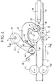
- FIG. 4 represents a top view of this exemplary embodiment, with all of its parts, but without an envelope.
- the arm 44 is separated so that the counter-roller 12 does not interfere with the visibility of the cone 20 and of the roller 5.
- the drive rollers 50 and 51 are arranged symmetrically with respect to the chute 4 located at the entrance to the device.
- the guides 30 and 31 are located in the extension of the chute 4.
- this point F ' is located near the axis C of the cone 20, that is to say on the same side as the axis C with respect to a plane orthogonal to the plane of the envelope and passing through the axis E.
- This arrangement of the axis of rotation G of the idler 5, and of the axis of rotation E of the drive roller 11 has the effect of slightly arching the body of an envelope around the axis E. This bending facilitates the creation of the space 9, shown in the previous figures, between the flap 2 and the body 1 of an envelope.
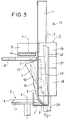
- Figure 5 shows a side view of this embodiment, more detailed, with a section along the view direction VV.
- the envelope 1, 2 is shown at the moment when the cone 20 enters the space 9 created between the body 1 and the flap 2 by the bending that the idler roller 5 produces collaborating with the drive roller 11.
- L envelope 1, 2 is driven in the direction indicated by arrow 13, that is to say away from the observer.
- This figure also shows the bending produced by the counter-roller 12, the drive roller 11 and the roller 5, bending which appears in particular at the top of the figure: a part of the body 1 is not perpendicular to the plane of the figure because of this bending around the axis E of the roller 11.
- the flap 2 has a triangular shape.
- the edge of the flap 2 is in contact with the cone 20 at a contact point 52.
- the point 52 moves both on the cone 20 and on the edge of the flap 2 as the envelope is driven in the device.
- Point 52 moves towards the tip of the flap 2 and it moves towards the base of the cone 20.
- the flap 2 is separated from the body 1 by the cone 20 without it there is the slightest collision during this movement. There is therefore very little risk of tearing.
- the region of the cone 20 located near the drive roller 11 comprises a generator 49 which is tangent to the surface of the body 1.
- the cone 20 shaves the surface of the body 1 and has all the chances of entering the space 9 between the flap 2 and the body 1.
Landscapes
- Supplying Of Containers To The Packaging Station (AREA)
- Folding Of Thin Sheet-Like Materials, Special Discharging Devices, And Others (AREA)
- Sheets, Magazines, And Separation Thereof (AREA)
Applications Claiming Priority (2)
| Application Number | Priority Date | Filing Date | Title |
|---|---|---|---|
| FR9014297 | 1990-11-16 | ||
| FR9014297A FR2669270A1 (fr) | 1990-11-16 | 1990-11-16 | Dispositif pour ouvrir des enveloppes. |
Publications (2)
| Publication Number | Publication Date |
|---|---|
| EP0485932A1 true EP0485932A1 (de) | 1992-05-20 |
| EP0485932B1 EP0485932B1 (de) | 1995-02-15 |
Family
ID=9402278
Family Applications (1)
| Application Number | Title | Priority Date | Filing Date |
|---|---|---|---|
| EP91119193A Expired - Lifetime EP0485932B1 (de) | 1990-11-16 | 1991-11-11 | Vorrichtung zum Öffnen von Briefumschlägen |
Country Status (4)
| Country | Link |
|---|---|
| US (1) | US5156585A (de) |
| EP (1) | EP0485932B1 (de) |
| DE (1) | DE69107412T2 (de) |
| FR (1) | FR2669270A1 (de) |
Cited By (3)
| Publication number | Priority date | Publication date | Assignee | Title |
|---|---|---|---|---|
| WO1993017880A1 (en) * | 1992-03-06 | 1993-09-16 | Printed Forms Equipment Limited | Envelope opening mechanism for inserter apparatus |
| WO1994027832A1 (en) * | 1993-05-21 | 1994-12-08 | Longford Equipment International Limited | Envelope stuffing machine |
| US5430990A (en) * | 1992-09-18 | 1995-07-11 | Long John A | Envelope stuffing apparatus |
Families Citing this family (9)
| Publication number | Priority date | Publication date | Assignee | Title |
|---|---|---|---|---|
| GB9001758D0 (en) * | 1990-01-25 | 1990-03-28 | Printed Forms Equip | Inserter apparatus |
| US5236408A (en) * | 1992-07-21 | 1993-08-17 | International Paper Box Machine Company, Inc. | Method and apparatus for forming carton blanks with hemmed edges |
| DE19836236A1 (de) * | 1998-08-05 | 2000-02-10 | Francotyp Postalia Gmbh | Vorrichtung zum Befeuchten der Leimkante von Umschlagklappen von Briefumschlägen |
| US6453651B1 (en) * | 2000-08-01 | 2002-09-24 | Todd C. Werner | High speed machine for inserting sheets into envelopes |
| US6718731B1 (en) * | 2001-08-01 | 2004-04-13 | Pitney Bowes Inc. | High speed machine for inserting sheets into envelopes |
| EP1468840B1 (de) * | 2003-04-14 | 2010-08-25 | Böwe Bell + Howell Company | Vorrichtung zur Kontrolle der Umschlagklappe während der Kuvertierung |
| US7797914B2 (en) * | 2007-12-31 | 2010-09-21 | Pitney Bowes Inc. | Method and device for holding envelopes during insertion |
| EP2347917A1 (de) * | 2010-01-22 | 2011-07-27 | Neopost Technologies | Einführen von Postsendungen in Umschläge |
| US12129145B2 (en) * | 2021-05-27 | 2024-10-29 | Ricoh Company, Ltd. | Enclosing apparatus and image forming system |
Citations (2)
| Publication number | Priority date | Publication date | Assignee | Title |
|---|---|---|---|---|
| US3935800A (en) * | 1974-04-08 | 1976-02-03 | Pitney-Bowes, Inc. | Flap separating mechanism |
| US3974749A (en) * | 1975-08-21 | 1976-08-17 | Pitney-Bowes, Inc. | Envelope flap separating and distending method and mechanism |
-
1990
- 1990-11-16 FR FR9014297A patent/FR2669270A1/fr not_active Revoked
-
1991
- 1991-11-01 US US07/786,842 patent/US5156585A/en not_active Expired - Lifetime
- 1991-11-11 EP EP91119193A patent/EP0485932B1/de not_active Expired - Lifetime
- 1991-11-11 DE DE69107412T patent/DE69107412T2/de not_active Expired - Fee Related
Patent Citations (2)
| Publication number | Priority date | Publication date | Assignee | Title |
|---|---|---|---|---|
| US3935800A (en) * | 1974-04-08 | 1976-02-03 | Pitney-Bowes, Inc. | Flap separating mechanism |
| US3974749A (en) * | 1975-08-21 | 1976-08-17 | Pitney-Bowes, Inc. | Envelope flap separating and distending method and mechanism |
Cited By (4)
| Publication number | Priority date | Publication date | Assignee | Title |
|---|---|---|---|---|
| WO1993017880A1 (en) * | 1992-03-06 | 1993-09-16 | Printed Forms Equipment Limited | Envelope opening mechanism for inserter apparatus |
| US5430990A (en) * | 1992-09-18 | 1995-07-11 | Long John A | Envelope stuffing apparatus |
| US5457941A (en) * | 1992-09-18 | 1995-10-17 | Longford Equipment International Limited | Envelope stuffing machine |
| WO1994027832A1 (en) * | 1993-05-21 | 1994-12-08 | Longford Equipment International Limited | Envelope stuffing machine |
Also Published As
| Publication number | Publication date |
|---|---|
| DE69107412T2 (de) | 1995-06-08 |
| FR2669270A1 (fr) | 1992-05-22 |
| DE69107412D1 (de) | 1995-03-23 |
| EP0485932B1 (de) | 1995-02-15 |
| US5156585A (en) | 1992-10-20 |
Similar Documents
| Publication | Publication Date | Title |
|---|---|---|
| EP0485932B1 (de) | Vorrichtung zum Öffnen von Briefumschlägen | |
| EP0388318B1 (de) | Verfahren und Vorrichtung zum Bilden eines neuen Stapels nach dem Abnehmen von einem fertigen Stapel, in einer, insbesondere einem Printer zugeordneten, Stapelbildungsmaschine | |
| EP0323296B1 (de) | Verfahren zur Bildung von Zickzackstapeln, ausgehend von einer Endlosbahn aus biegsamem Material und Maschine zur Durchführung dieses Verfahrens | |
| LU83610A1 (fr) | Pince de propulsion de trame | |
| FR2660642A1 (fr) | Dispositif pour enrouler un materiau mince, notamment des sacs en film plastique relies ensemble en un ruban. | |
| FR2510979A1 (fr) | Dispositif d'empilage pour une matiere en feuilles | |
| WO2002087892A1 (fr) | Imprimante pour l'impression de supports plans deformables et son chargeur | |
| FR2546818A1 (fr) | Dispositif pour ralentir les exemplaires dans un pli d'equerre de plieuse utilisee en relation avec les presses rotatives | |
| FR2481241A1 (fr) | Methode et dispositif pour separer des objets en feuille d'une pile | |
| FR2715642A1 (fr) | Dispositif pour tourner des pièces reposant à plat pendant leur avance. | |
| FR2515621A1 (fr) | Appareil a plier equipe d'un dispositif de guidage a bande destine a guider les feuilles | |
| EP0086867B1 (de) | Tragbare Etikettiermaschine | |
| EP0247523B1 (de) | Vorrichtung zum Öffnen von Briefumschlägen | |
| FR2475019A1 (fr) | Procede et dispositif d'enlevement individuel d'objets souples et plats de la partie inferieure d'une pile | |
| FR2634692A1 (fr) | Dispositif d'insertion de plis dans des enveloppes | |
| EP1145196B1 (de) | Vorrichtung zur ausgabe von karten | |
| FR2741299A1 (fr) | Systeme de depilage et d'ouverture d'enveloppes | |
| FR2720535A1 (fr) | Dispositif de lecture par machine d'informations apposées sur des objets plats. | |
| FR2862626A1 (fr) | Dispositif de taquage perfectionne pour machine de traitement de courrier | |
| EP1321311A2 (de) | Universelle Befeuchtungsvorrichtung für Klappe | |
| BE1010562A3 (fr) | Dispositif de division en troncons longitudinaux d'un matelas de carde. | |
| FR2721297A1 (fr) | Dispositif de dépilage d'objets minces empilés. | |
| EP1120288A1 (de) | Vorrichtung zum optimierten Verschliessen von Briefklappen | |
| FR2733491A1 (fr) | Dispositif de sortie d'exemplaires imprimes d'un dispositif a roues a aubes | |
| FR2483269A1 (fr) | Ouvreur de bobine |
Legal Events
| Date | Code | Title | Description |
|---|---|---|---|
| PUAI | Public reference made under article 153(3) epc to a published international application that has entered the european phase |
Free format text: ORIGINAL CODE: 0009012 |
|
| AK | Designated contracting states |
Kind code of ref document: A1 Designated state(s): DE FR GB |
|
| 17P | Request for examination filed |
Effective date: 19921117 |
|
| RAP1 | Party data changed (applicant data changed or rights of an application transferred) |
Owner name: NEOPOST INDUSTRIE |
|
| 17Q | First examination report despatched |
Effective date: 19940503 |
|
| GRAA | (expected) grant |
Free format text: ORIGINAL CODE: 0009210 |
|
| AK | Designated contracting states |
Kind code of ref document: B1 Designated state(s): DE FR GB |
|
| REF | Corresponds to: |
Ref document number: 69107412 Country of ref document: DE Date of ref document: 19950323 |
|
| GBT | Gb: translation of ep patent filed (gb section 77(6)(a)/1977) |
Effective date: 19950328 |
|
| PLBE | No opposition filed within time limit |
Free format text: ORIGINAL CODE: 0009261 |
|
| STAA | Information on the status of an ep patent application or granted ep patent |
Free format text: STATUS: NO OPPOSITION FILED WITHIN TIME LIMIT |
|
| 26N | No opposition filed | ||
| PGFP | Annual fee paid to national office [announced via postgrant information from national office to epo] |
Ref country code: FR Payment date: 19991011 Year of fee payment: 9 |
|
| PGFP | Annual fee paid to national office [announced via postgrant information from national office to epo] |
Ref country code: DE Payment date: 19991028 Year of fee payment: 9 |
|
| PGFP | Annual fee paid to national office [announced via postgrant information from national office to epo] |
Ref country code: GB Payment date: 19991029 Year of fee payment: 9 |
|
| PG25 | Lapsed in a contracting state [announced via postgrant information from national office to epo] |
Ref country code: GB Free format text: LAPSE BECAUSE OF NON-PAYMENT OF DUE FEES Effective date: 20001111 |
|
| GBPC | Gb: european patent ceased through non-payment of renewal fee |
Effective date: 20001111 |
|
| PG25 | Lapsed in a contracting state [announced via postgrant information from national office to epo] |
Ref country code: FR Free format text: LAPSE BECAUSE OF NON-PAYMENT OF DUE FEES Effective date: 20010731 |
|
| PG25 | Lapsed in a contracting state [announced via postgrant information from national office to epo] |
Ref country code: DE Free format text: LAPSE BECAUSE OF NON-PAYMENT OF DUE FEES Effective date: 20010801 |
|
| REG | Reference to a national code |
Ref country code: FR Ref legal event code: ST |