EP0486053B1 - Véhicule pour le nettoyage des plages - Google Patents
Véhicule pour le nettoyage des plages Download PDFInfo
- Publication number
- EP0486053B1 EP0486053B1 EP91119542A EP91119542A EP0486053B1 EP 0486053 B1 EP0486053 B1 EP 0486053B1 EP 91119542 A EP91119542 A EP 91119542A EP 91119542 A EP91119542 A EP 91119542A EP 0486053 B1 EP0486053 B1 EP 0486053B1
- Authority
- EP
- European Patent Office
- Prior art keywords
- vehicle according
- rotor
- pickup
- chassis
- rubbish
- Prior art date
- Legal status (The legal status is an assumption and is not a legal conclusion. Google has not performed a legal analysis and makes no representation as to the accuracy of the status listed.)
- Expired - Lifetime
Links
- 238000004140 cleaning Methods 0.000 title claims description 14
- 239000004576 sand Substances 0.000 claims description 36
- 230000007246 mechanism Effects 0.000 claims 7
- 239000002699 waste material Substances 0.000 description 40
- 239000012535 impurity Substances 0.000 description 12
- 239000000356 contaminant Substances 0.000 description 11
- 230000032258 transport Effects 0.000 description 11
- 230000008878 coupling Effects 0.000 description 9
- 238000010168 coupling process Methods 0.000 description 9
- 238000005859 coupling reaction Methods 0.000 description 9
- 238000005253 cladding Methods 0.000 description 7
- 239000000463 material Substances 0.000 description 6
- 238000000926 separation method Methods 0.000 description 4
- 241000195493 Cryptophyta Species 0.000 description 3
- 238000011109 contamination Methods 0.000 description 3
- 239000010985 leather Substances 0.000 description 3
- 239000002689 soil Substances 0.000 description 3
- 239000010426 asphalt Substances 0.000 description 1
- 230000015572 biosynthetic process Effects 0.000 description 1
- 239000004566 building material Substances 0.000 description 1
- 238000005352 clarification Methods 0.000 description 1
- 238000010276 construction Methods 0.000 description 1
- 230000007423 decrease Effects 0.000 description 1
- 230000000694 effects Effects 0.000 description 1
- 230000002349 favourable effect Effects 0.000 description 1
- 230000005484 gravity Effects 0.000 description 1
- 238000007654 immersion Methods 0.000 description 1
- 239000002184 metal Substances 0.000 description 1
- 230000002093 peripheral effect Effects 0.000 description 1
- 229910000679 solder Inorganic materials 0.000 description 1
- 239000000758 substrate Substances 0.000 description 1
- 239000000725 suspension Substances 0.000 description 1
- 230000008719 thickening Effects 0.000 description 1
Images




Classifications
-
- E—FIXED CONSTRUCTIONS
- E01—CONSTRUCTION OF ROADS, RAILWAYS, OR BRIDGES
- E01H—STREET CLEANING; CLEANING OF PERMANENT WAYS; CLEANING BEACHES; DISPERSING OR PREVENTING FOG IN GENERAL CLEANING STREET OR RAILWAY FURNITURE OR TUNNEL WALLS
- E01H12/00—Cleaning beaches or sandboxes
Definitions
- the invention relates to a vehicle for beach cleaning with a vehicle frame, at least one wheel axle arranged thereon, with a height-adjustable waste pickup, a adjoining latter, the waste taken over from the waste pickup to a conveyor arranged at the rear end of the vehicle frame (such as from the EP -A-0 387794) and a feed rotor assigned to the feed area of the garbage collector.
- Such a beach cleaning vehicle is also known from US-A-4,482,019.
- waste from the ground is z.
- B. a sandy beach and transferred to a conveyor belt.
- the tines of the feed rotor are curved at their ends in the direction of travel, the rotor rotates in the same direction.
- the speed of rotation of the rotor is added to the driving speed in the receiving area, so that the waste is thrown tangentially forward in the direction of travel when it comes into contact with the tines. In this way, contaminants can accumulate in front of the feed rotor and impair further use.
- the tines are heavily loaded when they hit the dirt or sand due to the high relative speed and can break.
- Fibrous impurities such as algae can wrap around the feed rotor and the sinks and become matted with them due to the rotation of the feed rotor and the long entrainment until delivery to the conveyor belt.
- the known feed rotor must frequently be cleaned and freed from the algae.
- the entire vehicle frame with all the devices attached to it is lowered.
- the wheels mounted on a bracket-shaped bracket are pivoted backwards by an actuating device and the entire vehicle is thereby lowered.
- a height adjustment of the feed rotor relative to the conveyor belt is not possible.
- the distance between the feed rotor and the conveyor belt cannot be varied. Bulky impurities cannot be picked up and may damage the vehicle.
- a separation of impurities and sand takes place in the previously known beach vehicle only with the help of a sieve belt arranged after the conveyor belt. It must have both the contaminants and the sand transport. This can put a heavy load on the vehicle, particularly in the case of damp sand.
- part of the sand with the impurities is transported to the collection container. The collection container is filled prematurely and must be exchanged for another container or emptied.
- the invention has for its object to provide a vehicle for beach cleaning of the type mentioned, which is improved when feeding, picking up and transporting waste and when separating the waste from the sand and when disposing of the contaminants.
- a swivel frame carrying the garbage collector and the feed rotor for height adjustment is lowered on the vehicle frame, on which the feed rotor by means of a handlebar over a different operating positions swiveling range from the front is pivotally mounted to the rear and can be rotated, in particular counterclockwise, about a horizontal axis of rotation mounted on the links.
- the feed rotor is arranged in a first, front operating position for feeding garbage and / or sand to the waste pickup in the direction of travel in front of a receiving wedge strip arranged at the front of the waste pickup, in a second, middle operating position the distance between the receiving wedge strip and the feed rotor is minimal and in one In the third, rear operating position, the feed rotor is arranged at a greater distance from the receiving wedge strip or from the waste pickup above compared to the second operating position.
- the waste pick-up is lowered down to or into the sand with the holding wedge strip.
- the impurities and possibly sand are absorbed via the wedge ledge.
- the feed rotor is also lowered. Since this is pivotably mounted relative to the waste pickup, both the distance from the feed rotor to the waste pickup or wedge bar and the height of the feed rotor relative to the sand can be varied independently of the waste pickup.
- the feed rotor In a first operating position, the feed rotor is arranged in the direction of travel in front of the wedge bar and thus also in front of the waste collector. If in this position the wedge bar rests roughly on the sand, the feed rotor rotates above the sand or penetrates the sand surface only slightly. In this position, the feed rotor feeds all surface contaminants to the waste collector. Only a small amount of sand is taken up and therefore a high driving speed is possible. In addition, since the rotor rotates counterclockwise, the rotation speed and the vehicle speed do not add up, which leads to a lower load on the rotor. This throws the impurities in the direction of the wedge ledge and garbage collector, at the same time a partial separation of the contamination occurs depending on its weight. Lighter impurities are thrown further towards the waste collector than heavier ones, e.g. B. sand.
- Any impurities not detected by the feed rotor are subsequently removed by the Wedge ledge picked up and passed on to the waste collector. In this way, all debris is absorbed by the beach up to a certain immersion depth and this is cleaned intensively.
- the first operating position is particularly advantageous in the case of wet sand or in the flood zone area, since only a small amount of sand is absorbed and the surface is cleaned thoroughly.
- the second operating position of the feed rotor is preferably used.
- the rotor not only serves to supply contaminants to the waste collector, but also to accelerate the sand and the contaminants taken up by the wedge bar.
- the wedge bar is partially immersed in the sand.
- the feed rotor forming a channel with the wedge ledge partly covers the sand and in particular the garbage lying superficially on the sand. Similar to the first operating position, the rotor throws the materials in its rotating area towards the waste collector. The lighter parts are thrown further than the heavier parts. In this way, sand and impurities are already partially fed to the waste collector and are easier to separate from each other on this. At the same time, the accelerated forwarding of the materials picked up enables a higher driving speed.
- the wedge bar can recorded parts are carried out in the gap formed between the rotor and the wedge bar to the waste collector.
- the rotation of the rotor supports further transport.
- claims 2 and 3 are also advantageous, since in this way the swivel frame is of simple design and is arranged completely below the vehicle frame.
- the top of the vehicle frame can also be used in a variety of ways, such as. B. for transporting building material, soil, nursery items or the like.
- the swivel frame itself can be lowered by the storage at its rear end with its end lying in the direction of travel. At this end feed rotor and wedge bar are arranged.
- claims 4 and 5 are advantageous in that a versatile use of the vehicle is possible in this way.
- the swivel frame can be exchanged together with the waste pick-up and feed rotor with the help of detachable quick-release fasteners for another swivel frame with corresponding devices. Converting the vehicle to other areas of application is possible without spending a lot of time. This increases the flexibility of the vehicle. For example, use for cleaning asphalt roads is also possible, in which case the receiving wedge strip is preferably elastic and the feed rotor is designed in particular as a brush roller is.
- the vehicle can also be used for general transport without a swivel frame.
- claims 6 to 9 are also advantageous, since in this way the refuse collector can be used for many areas of application.
- the contaminants are taken over by the elevator from the feed rotor or the wedge ledge and passed on to the downstream conveyor. If the elevator has its own drive, its speed can be set independently of the speed of rotation of the feed rotor or the speed of the conveyor and can be easily adapted to applications with different amounts of waste.
- the construction of the vehicle according to claims 10 to 12 is also favorable.
- the draw-in area of the wedge ledge, feed rotor and garbage collector can be designed according to the vehicle width.
- the width of the waste stream is reduced in accordance with the specified conditions via the arranged side coulters and guide plates and is thus, for. B. between the wheels attached to the wheel axle.
- the contaminants are absorbed before they are possibly compacted with the wheels of the vehicle or even pressed into the ground, and the sand is cleaned across the entire width of the vehicle.
- a larger width would be z. B. the wedge bar possible, but this would complicate the handling of the vehicle and people may be injured by the ends of the wedge bar protruding laterally from the vehicle contour.
- the features of the protection claims 13 and 14 are advantageous in that with the help of the adjusting device e.g. B. automatically controlled lowering and lifting of the swivel frame is possible.
- the actuating device can be designed as a hydraulic actuating cylinder and z. B. be operated remotely by the driver of the vehicle.
- the adjusting device is arranged on the side of the frame.
- the angle of incidence relative to the garbage pickup of the receiving wedge strip is greater than the angle of incidence of the garbage pickup. In this way, in the second operating position between the receiving wedge strip and the feed rotor, a narrowing transport channel is obtained for the further transport of waste and sand that has been taken in, the end of the transport channel having a larger opening angle and the material taken up thereby being better distributed over the waste collector.
- the rotor is thus easily accessible.
- the arrangement of the flange bearings and bearing brackets makes it very easy to swivel over the swivel range encompassing the operating positions.
- the swivel radius of the feed rotor is relatively large, and yet it is possible to swivel the swivel frame close to the vehicle frame, with flange bearings and bearing brackets of the rotor being arranged laterally next to the vehicle frame. Due to the special bearing of the rotor axis of rotation, a fine height adjustment of the rotor is also possible.
- a drive device is assigned to one end of the rotor axis of rotation.
- This can be a hydraulic motor that is connected to the hydraulic system of the vehicle and can be adjusted by the driver if necessary.
- claims 23 and 24 are also advantageous, since the actuating device for pivoting the rotor allows it to be pivoted independently of the waste pickup.
- the actuator can, for. B. be designed as a hydraulically actuated piston. So that no greater leverage occurs, the Actuator attached with one end close to the rotor axis of rotation. In order to further facilitate the pivoting, the other end of the adjusting device is arranged on a side wall of the impact cladding.
- the feed rotor has a plurality of radially projecting tines which determine the rotor circumference. With the help of the tines, the impurities or the sand are thrown in the direction of the wedge ledge or the waste collector.
- the tines can be designed as elastic tines made of metal or plastic which are fixedly arranged on the axis of rotation of the rotor. It is also possible to store the tines spring loaded.
- the receiving wedge bar extends in the direction of travel essentially in a direction parallel to a tangent of a pivoting curve, the pivot curve being determined as the envelope of a part of the rotor circumference lying opposite the pivot bearing.
- a deflection axis can be designed as an unbalanced shaft on the conveyor as well as on the garbage collector and can make shaking off the sand or the soil material easier by means of a targeted oscillating movement that runs vertically to the transport direction.
- the front cross member of the vehicle frame laterally protrudes beyond the longitudinal members to approximately the vehicle width and the actuating devices are supported at its ends.
- tipping devices for a loading area arranged on the vehicle frame can also be mounted at these ends.
- the vehicle frame is essentially formed by a frame rectangle formed by two long beams and two cross beams and a frame triangle arranged at its front end.
- a coupling device for a towing vehicle is arranged at the top of the frame triangle.
- the collecting container can be pivoted over the leather surface by means of two supports arranged on the side of the vehicle frame or on the leather surface and can be emptied evenly onto the leather surface.
- the features of the protection claims 35 to 37 are advantageous in that with the aid of the rocker arms, a uniform pouring out of the collecting container is possible over the entire length of the loading area.
- the first garbage is placed over a pouring edge of the collecting container emptied onto the loading area directly above the rear end and gradually pivoted further by the arrangement of the tilting link and carrier of the collecting container during the pivoting to the front end of the loading area.
- Due to the triangular connection frame the carrier of the collecting container can be rotated from a substantially horizontal position into an approximately vertical position with the aid of a tilting device.
- Both the tilting device for the collecting container and the tilting device for the loading area can be designed as hydraulically actuated pistons.
- a further development of the vehicle according to claims 38 to 40 is also expedient.
- a height adjustment of the rear end of the vehicle is possible due to the wheel axle designed as a lift axle.
- the vehicle frame is raised with the aid of the lifting device and the collected garbage can also be tipped into a higher container.
- FIG. 1 the vehicle according to the invention for beach cleaning 1 is shown together with a towing vehicle 2.
- the beach cleaning vehicle 1 is connected to the latter by means of a coupling device 3 and a coupling device 77 formed on the towing vehicle 2 and is movable over a base 68.
- the vehicle 1 is essentially from the Vehicle frame 4, a folded-up loading area 5, a swiveling frame 7 arranged under the vehicle frame 4 and a collecting container 6 pivoted over the loading area 5 are formed.
- the coupling device 3 is arranged on the vehicle frame 4 at its front end and an essentially horizontal tilting axis 51 for the loading area 5 is arranged at its rear end.
- the loading area 5 is pivoted upward about 45 ° relative to the vehicle frame 4 about the tilt axis 51.
- an adjustable rear wall 50 which is pivotably mounted at the rear upper end of the loading area 5, is partially open.
- a collecting container swiveling device 39 is arranged on a side wall 87 of the loading area near the underside facing the vehicle frame. This runs essentially parallel and closely adjacent to the underside of the side surface 87.
- the pivoting device 39 is mounted on the side surface 87 at a front end 40, while the rear end 41 is mounted on the tip of a triangular frame element 48, 49.
- the ends of the legs 48 and 49 of the triangular frame element are connected to a carrier 42.
- This and the triangle legs enclose an essentially equilateral triangle.
- the triangular leg 48 and the carrier 42 In the vicinity of the connection between the triangular leg 48 and the carrier 42, the latter is pivotably mounted on the underside of the side wall 87 of the loading surface 5 at its end 43.
- the collecting container 6 At the opposite end 44, the collecting container 6 is pivotably mounted relative to the carrier 42.
- the end 44 of the carrier 42 is arranged approximately in the center of gravity of a side surface of the collecting container 6.
- a cross member 45 extends at right angles to the carrier 42 along the collecting container 6.
- a rocker arm 46 is rotatably mounted on the side wall 87 of the loading surface 5 adjacent to the end 43 of the carrier 42.
- the bearing point 164 of the rocker arm 46 is shown in FIGS. 2 and 3 and is offset relative to the bearing point 43 of the support 42 in the direction of the upper edge of the side wall 87.
- the rocker arm 46 is rotatably mounted on the collecting container 6. This end lies essentially offset on a straight line which runs vertically to the bottom surface and runs through the end point 44 of the carrier 42 in the direction of the top of the collecting container 6.
- the rocker arm 46 is formed with a somewhat shorter length than the carrier 42.
- a loading surface tipping device 36 which is arranged between a cross member 35 of the frame 4 and the side surface 87 of the loading surface 5, the latter is pivoted relative to the vehicle frame 4.
- the tilting device 36 is rotatably supported at one end 37 on the cross member 35 and is arranged at the other end 38 approximately above the end 43 of the carrier 42 in the center of the side wall 87.
- an actuating device 32 Opposite the end 37 of the tilting device 36, an actuating device 32 with one end 34 is rotatably mounted on the cross member 35. With its other end 33, it is rotatably mounted on a swivel frame 7 arranged below the vehicle frame 4.
- the swivel frame 7 can be lowered in the direction of the floor 68 about an essentially horizontal swivel axis 8 arranged in the vicinity of its rear end.
- a number of rollers 20, 21, 24, 25, 26, 27 and 28 are rotatably mounted in the swivel frame 7.
- the rollers 20 and 21 serve as deflection axes for a conveyor belt formed from upper run 22 and lower run 23.
- the rollers 24, 25 and 26 are designed as support rollers and, together with the deflection axes 20 and 21, define a transport plane of the upper strand 22.
- the rollers 27 and 28 are each arranged between the deflection axes 20 and 21 and the support rollers 24 and 26 adjacent to them.
- rollers 27 and 28 serve as tensioning rollers and are arranged below the lower run 23 and guide it in the direction of the upper run 22.
- the lower run 23 between the tensioning rollers 27 and 28 sags in the direction of the bottom 68.
- a baffle cover 15 is arranged on the swivel frame 7 above the deflection axis 20 and the support roller 24. This points from the swivel frame 7 in the direction of the vehicle frame 4.
- a cover 16 of the impact lining 15 with the underside of the vehicle frame 4 is in contact over its entire length.
- the end 33 of the actuating device 32 is arranged near the swivel frame 7.
- a guide plate 65 which extends in the longitudinal direction of the swivel frame and extends above the upper run 22.
- an adjusting device 29 extends between a rear upper edge of the impact cladding 15 and a feed rotor 11 arranged in front of it. It is mounted at its rear end 31 on the impact cladding 15 and at its front end 30 on the feed rotor 11.
- the feed rotor 11 is rotatable about an axis of rotation 18. It has a plurality of radially projecting tines 67.
- a drive device cover 17 extends between the axis of rotation 18 and the vehicle frame 4. This partially projects laterally beyond the vehicle frame 4.
- a bearing bracket 19 is directed toward the upper end of the cover 17. This is arranged on a front edge of the cover 16 of the impact lining 15.
- a side sheet 64 partially covering this laterally is arranged as an extension of the swivel frame 7.
- the height of the side coulter 64 corresponds approximately to the height of the end of the swivel frame 7 that is adjacent to it above, wherein it runs approximately parallel to the opposite end of the swivel frame 7 pointing towards a conveyor 12.
- the conveyor 12 is arranged between the wheel axle 13 and the vehicle frame 4. It has an inclination essentially corresponding to the swivel frame.
- the transport direction of the conveyor 12 and of the waste pickup 9 arranged in the swivel frame 7 is the same and in the direction of the rear end of the vehicle 1 directed. Similar to the swivel frame 7, the conveyor 12 also has side-guiding plates 66.
- FIG. 1 the vehicle frame 4 is shown lifted relative to the wheel axle 13.
- Two support arms 62 and 63 connected to the vehicle frame 4 point from the vehicle frame in the direction of the wheel axis 13.
- a lifting cylinder 61 is arranged centrally between them.
- a lifting piston 60 is almost completely extended from the lifting cylinder 61, with a holding part 59 partially encompassing the wheel axle 13 being arranged at its end. This has a cross section similar to an isosceles triangle.
- the reciprocating piston 60 is connected in the center to the base of this triangle.
- a height-adjustable adjusting wheel 162 for parking the vehicle 1 is arranged near the coupling device 3 perpendicular to the vehicle frame 4.
- FIG. 2 shows the beach cleaning vehicle 1 with the pivot frame 7 lowered to the floor 68.
- the same parts are provided with the same reference numerals as in FIG. 1 and are only mentioned in part.
- the loading area 5 is placed on the vehicle frame 4 in this figure.
- the tilting device 36 moves its end 38 along the circular arc 72, the loading surface 5 assuming approximately the position shown in FIG. 1 at the end of the circular arc.
- the tip 41 of the triangular frame part can be guided along the semicircular arc 71 with the aid of the collecting container swiveling device 39.
- the position of the collecting container 6 shown which is pivoted as far as possible over the loading surface 5 and the triangular tip 41 points in the direction of the pivoting device 39, is in the position of the collecting container 6 shown in FIG. 2, this near the bottom 68 below the rear deflection axis 53 the conveyor 12 arranged.
- the center area 44 of the collecting container 6 moves along the circle 69 to the position of the collecting container 6 '.
- the end point 47 of the rocker arm 46 moves along the arch 70. Due to the relative arrangement and length of the carrier 42 and the rocker arm 46 described in FIG. 1, the corresponding guide arch 69 and 70 intersect and the open end of the collecting container 6 is more and more pointed Direction of the loading area 5 and can be emptied via a pouring edge 161 in the direction of the loading area 5.
- the swivel frame 7 is lowered around the laying point 8 at one end to the floor 68.
- a receiving wedge strip 10 arranged below the feed rotor 11 on the swivel frame 7 touches the bottom 68 with its free end, and the side sheet 64 runs with its underside essentially parallel to the bottom.
- the beach cleaning vehicle 1 is shown in a plan view.
- the vehicle frame 4 has a triangular frame section connected to the coupling device 3 and a rectangular section section adjoining this.
- the triangular frame section is formed by two supports 81 and 82 running symmetrically to the longitudinal direction 100 of the coupling device 3 in the direction of a first cross member 35.
- the triangular tip is arranged in the coupling device 3, while the triangular base is formed by the cross member 35.
- Parallel to the longitudinal axis 100 are connected to the beams 81 and 82, longitudinal beams 75 and 76.
- the rectangular frame section is formed by these beams, the cross beam 35 and a cross beam 78 arranged near the vehicle end.
- the longitudinal members 75 and 76 are at a distance corresponding to the distance between the wheels 14 and 14 '.
- the loading surface 5 is pivotally mounted, these ends projecting beyond the cross member 78 to the rear.
- the cross member 78 extends from one longitudinal member to the other, the longitudinal member 35 parallel to the latter has a greater length. With its ends 79 and 80, it protrudes on both sides of the side members by the same length in each case.
- the actuators 32 and 36 are pivotally mounted.
- the loading area 5 is arranged lying thereon.
- a front wall 88, two side walls 87 and 89 and a rear wall 50 can be seen from the loading area 5.
- the side walls or front and rear walls are parallel to the longitudinal beams 75 and 76 or cross beams 35 and 78 and form the rectangular loading area 5.
- the rear wall 50 runs, as shown in FIG. 2, at an angle to the vertical towards the rear toward the collecting container 6. While the upper edge of the rear wall 50 is arranged in front of the collecting container, the lower edge closer to the collecting container is arranged above an opening 90 of the collecting container 6.
- the pouring edge 161 is thus located below the loading area 5.
- the pouring edge and its opposite side of the collecting container run essentially parallel to the rear wall 50.
- the extent of the collecting container 6 perpendicular to the longitudinal direction 100, ie its width, is slightly shorter than the inner distance between the side walls 87 and 89 of the loading area.
- the collecting container 6 is connected in the center via the bearings 44 and 44 'or 47 and 47' to the carrier 42 and 42 'or the rocker arms 46 and 46'.
- the brackets 42 and 42 ' run parallel to the rocker arms 46 and 46' outside the side walls 87 and 89.
- both the brackets 42 and the rocker arms 46 are with the side wall 87 and correspondingly on the other side with the side wall 89 connected.
- the pivoting device 39 runs between a first bearing point 40 and a second bearing point 41. This is above the carrier 42 according to FIG. 1 and 2 designed as a triangular tip.
- the distance from the carrier 42 and the collecting container swiveling device 39 to the side wall 87 is essentially the same. The same applies to the collecting container swiveling device 39 'on the other side wall 89 of the loading area 5.
- a hydraulic cover 91 is arranged on the triangular frame section formed by the supports 81 and 82. This extends symmetrically to the longitudinal direction 100, with its side surfaces running essentially parallel to and projecting above the supports 81 and 82.
- the cover 16 is arranged symmetrically to the longitudinal direction 100. On both sides, it protrudes somewhat relative to the side walls 87 and 89 of the loading area 5, the adjusting devices 29 and 29 'being arranged on these sides.
- the distance between these adjusting devices essentially corresponds to the distance between the collecting container pivoting devices 39 and 39 'or the distance between the supports 42 and 42'.
- bearing tabs 19 and 19 ' are arranged symmetrically to the longitudinal direction. These are in engagement with bearing devices 85 and 86 of a frame 84.
- the frame 84 runs parallel to the front of the cover 16 and projects beyond it laterally through two arms directed in the direction of the adjusting devices 29 and 29 '.
- the drive device cover 17 is arranged on one side of the frame 84, with a motor 83 protruding from the cover 17 in the direction of the longitudinal axis of the frame 84.
- the beach cleaning vehicle 1 is shown in a plan view of the garbage collector 9, the conveyor 12 and the collecting container 6.
- Both the run 22 of the garbage collector 9 and the run 58 of the conveyor 12 are designed as sieve belts. These have a plurality of essentially diamond-shaped openings.
- two side coulters 64 and 64 ′ which are angled outward symmetrically to the longitudinal direction 100, are arranged at the ends of the wedge strip 10.
- the receiving width 92 of the side coulters 64 and 64 ' essentially corresponds to the vehicle width 93.
- the wedge ledge 10 protrudes from the waste pickup 9 approximately over half the longitudinal extent of the side coulters 64 and 64' in the direction of the coupling device 3.
- Adjoining plates 96 and 97 running on both sides symmetrically to the longitudinal direction 100 adjoin these ends.
- a drive device 98 is arranged on one side on the rear deflection axis 21. At least the support rollers 25 and 26 are drive-connected to the deflection axis 21 by drive connections 99.
- the conveyor 12 also has an output device 101 arranged on one side on its rear deflection axis 53.
- the frame 84 is essentially U-shaped.
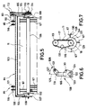
- a U-web 103 runs horizontally and parallel to the rotor pivot axis 120 or rotor rotation axis 18. At its ends, the U-web 103 has U-legs 104 and 105 arranged at right angles to this. These extend to almost above a rotor shaft 106 which is concentric with the axis of rotation 18.
- Bearing flanges 107 and 108 are arranged at the ends 109 and 110 of the U-legs 104 and 105. These are placed on the U-legs 104 and 105 from the outside and connected to them.
- the axis of rotation 18 is mounted in the bearing flanges 107 and 108.
- Concentric rotor end disks 132 and 133 are arranged on the axis of rotation 18. These limit the feed rotor 11 in the direction of the axis of rotation.
- a plurality of radially projecting tines 67 are arranged on the rotor shaft 106. For clarification, only a few tines are shown in FIG. 5.
- Bearing devices 85 and 86 are arranged on the U-web 103 for mounting the feed rotor 11 on the swivel axis 120. These are each formed by a pair of bearing flanges 116, 117 and 118, 119. The bearing flanges have a corresponding opening to accommodate the swivel axis.
- a drive device 111 is arranged on one side of the feed rotor 11. This comprises a motor 112 arranged above the U-web 103 and a drive pulley 113 mounted on its drive axle. This is connected via a V-belt 115 to a drive pulley 114 arranged coaxially on the axis of rotation.
- FIG. 6 shows a side view, in particular of the flange stop 108.
- This is essentially U-shaped.
- elongated holes 123 and 124 are arranged symmetrically to an elongated groove receiving the axis of rotation.
- a U-leg has a thickening in which a bore 30 is arranged.
- One end of the actuating device 29 can be stored in this bore.
- a U-leg 105 of the frame 84 from FIG. 5 is visible above the bearing flange 108. Both the longitudinal groove 122 and the U-leg 105 extend vertically in the direction 125. At the upper end of the U-leg 105, the bearing flange 119 runs in the direction 126. This has at its free end a pivot bearing bore 121. Angle 127 is included between direction 125 of longitudinal groove 122 and direction 126 of bearing flange 119.
- FIG. 7 shows the drive device of the feed rotor 11.
- the rotor end disk 133 is arranged concentrically to the axis of rotation 18. Tines 67 protrude radially from these and fix the circumferential line 129 when rotated in the direction 128.
- the drive pulley 114 is connected to it coaxially with the axis of rotation 18.
- the drive pulley 113 connected to the motor is arranged vertically above this drive pulley. Both are connected to the drive via a V-belt 115.
- a tensioning roller 131 For tensioning the V-belt, a tensioning roller 131, which is offset laterally to the connecting line of these two, is arranged between the drive pulleys 113 and 114.
- the feed rotor 11 is pivoted forward about the pivot bearing axis 120 with the aid of the adjusting device 29.
- the deepest point of the feed rotor 11 is located near the surface 68 and in front of the receiving wedge strip 10.
- the tines 67 engage in a layer of waste 136 lying on the surface when rotated counterclockwise 128. Both by rotating the feed rotor 11 and by moving the vehicle in the direction 140, the waste 136 is conveyed onto the upper run 22 of the waste receiver via the receiving wedge strip 10. This transports the garbage in the direction of 137.
- the receiving wedge strip 10 In the operating position shown in FIG. 8, the receiving wedge strip 10 is arranged near the surface 68 but above it.
- the feed rotor 11 can be pivoted forwards with the aid of the adjusting device 29 until the length of the piston 138 corresponds approximately to the length of the adjusting device 29. In the position of the feed rotor pivoted furthest back, the piston 138 is completely retracted into the actuating device 29. The entire swivel range of the feed rotor corresponds essentially to the swivel arc 74 of the axis of rotation 18.
- a wedge-shaped recess 139 is arranged in a side wall 134 of the impact lining 15. This serves to receive the axis of rotation 18 when the feed rotor 11 is pivoted.
- FIG. 9 shows a second operating position of the feed rotor 11.
- the receiving wedge ledge 144 is inserted into the sand 135 to the depth d.
- Both sand 135 and waste 136 are arranged between the receiving wedge strip 10 and the feed rotor 11.
- the feed rotor 11 is pivoted so far to the rear that the distance e between the circumferential line 129 and the wedge strip 10 is minimal.
- Other characteristic sizes according to the Invention are the distance a from the tip 144 of the receiving wedge strip 10 and the perpendicular base 143 of the solder 142 placed by the pivot axis 120, and the distance b and c of the pivot axis 120 from the vertical base and from the plane formed by the receiving wedge strip 10.
- the receiving wedge strip forms an angle ⁇ with the horizontal which is larger by the angle 145 than the angle ⁇ enclosed between the upper strand 22 and the horizontal.
- the feed rotor 11 is shown in a third operating position.
- the piston 138 is fully inserted into the actuating device 29 and the feed rotor is arranged in its most pivoted rearward position. In this position, its peripheral line 129 almost touches the cover 16 from below and the axis of rotation 18 is inserted as far as possible into the cutout 139 of the side wall of the impact cladding.
- circumferential line 129 and upper run 22 are arranged at a distance f.
- the distance f is approximately twice the distance e between the circumferential line and the receiving wedge strip 10 in the second operating position.
- the distance e is the minimum distance.
- FIG. 11 shows the wheel axle 13 in a front view.
- a bottom wall 146 of the loading area 5 runs horizontally and lies on the cross member 78 of the vehicle frame. This is laterally enclosed by long beams 75 and 76.
- the loading area 5 in Side walls 82 and 87 enclosing the vertical direction are arranged above the longitudinal beams 75, 76 and offset to the outside thereof.
- the lifting cylinders are arranged directly below the longitudinal beams 75 and 76 and, like these, are arranged symmetrically to the central vertical axis 164 of the vehicle.
- Lower lifter mounts 149 and 150 are formed on each of the support members.
- the reciprocating pistons movable in the lifting cylinders are mounted on these. Above the lower lifting device fasteners 149 and 150, the ends of the lifting pistons 61 and 61 'are passed through lifting piston guides 147 and 148.
- the lifting device is shown in a side view.
- the upper lifting device mounting 153 is visible below the longitudinal beam 76.
- This is essentially formed by a profile arranged laterally on it parallel to the longitudinal beam 76.
- a hole 154 for supporting the upper end of the lifting cylinder 61 is formed in the center of this profile.
- Two support arms 62 and 63 pointing in the direction of the wheel axis are arranged on the longitudinal member 76 at the ends of the profile.
- a profile 148 for fixing the lower end of the lifting cylinder 61 is attached between the free ends of the support arms.
- the lifting cylinder 61 itself runs centrally to the support arms 62 and 63 which essentially enclose a triangle with the longitudinal beam 76. Below the In the illustration according to FIG.
- the profile 148 is arranged directly at the lower bearing point of the lifting device.
- the holding part 59 is shown abutting them. In cross section, this essentially has the shape of an isosceles triangle.
- the free ends of the support arms 62 and 63 abut the ends of the base line of this triangle.
- the lower bearing point 150 of the lifting device is arranged centrally between these free ends in the middle of the base line.
- the two legs of the triangle point in the direction of the wheel axis 13 and partially encompass them.
- FIG. 13 shows the lifting device with the lifting piston 60 extended to the maximum.
- the same reference numerals designate the same parts as in FIG. This is only partially addressed.
- the longitudinal member 76 is shown lifted upwards by the distance g with respect to the wheel axle 13.
- the free ends 157 and 158 of the support arms 62 and 63 have journals 155 and 156. These are arranged parallel to the lifting cylinder 61 or reciprocating piston 60 and point to the holding part 59.
- Corresponding bearing openings 159 and 160 are arranged in this, which in the illustration according to FIG. 12 are in engagement with the bearing pins 155 and 156.
Landscapes
- Engineering & Computer Science (AREA)
- Architecture (AREA)
- Civil Engineering (AREA)
- Structural Engineering (AREA)
- Cleaning Of Streets, Tracks, Or Beaches (AREA)
- Refuse-Collection Vehicles (AREA)
Claims (40)
- Véhicule pour le nettoyage des plages, comprenant un châssis de véhicule (4), au moins un essieu (13) monté sur celui-ci, un ramasseur de déchets (9) réglable en haureur, suivi d'un transporteur (12) transférant les déchers ramassés par le ramasseur de déchets (9) à un collecteur (6) monté à l'extrémité postérieure du châssis de véhicule (4), et un rotor d'alimentation (11) avec un axe de rotation (18) horizontal, associé à la zone d'entrée du ramasseur de déchets (9), caractérisé en ce qu'un châssis pivotant (7) portant le ramasseur de déchets (9) et le rotor d'alimentation (11) est monté sur le châssis de véhicule (4) de façon à pouvoir être abaissé pour le réglage en hauteur, que le rotor d'alimentation (11) est monté au moyen de bras oscillants (84) sur ledit châssis pivotant de façon à pouvoir être pivoté de l'avant vers l'arrière en haut sur une plage de pivotement (74) comprenant différentes positions de fonctionnement, et tourné, en particulier dans le sens antihoraire, autour d'un axe de rotation (18) horizontal monté sur les bras oscillants (84), dans une première position de fonctionnement antérieure l'amenée de déchets et/ou de sable au ramasseur de déchets (9), le rotor d'alimentation (11) étant disposé, dans la direction de marche (100), en avant d'un lardon conique de ramassage (10) monté à l'avant du ramasseur de déchets (9); dans une seconde position de fonctionnement médiane, la distance (e) entre le lardon conique de ramassage (10) et le rotor d'alimentation (11) étant minimale, et dans une troisième position de fonctionnement postérieure le rotor d'alimentation, (11) étant disposé plus haut et se situant par rapport à la seconde position de fonctionnement à une distance (f) plus grande du lardon conique de ramassage (10) et respectivement du ramasseur de déchers (9).
- Véhicule selon la revendication 1, caractérisé en ce que le châssis pivotant (7) ainsi que le ramasseur de déchets (9) et le rotor d'alimentation (11) sont disposés en dessous du châssis de véhicule (4).
- Véhicule selon l'une des revendications 1 ou 2 caractérisé en ce que le châssis pivotant (7) est constitué pour l'essentiel de longerons formant un rectangle et d'au moins une traverse, son extrémité postérieure étant couplée de manière tournante avec le châssis de véhicule (4).
- Véhicule selon l'une quelconque des revendications précédentes, caractérisé en ce que le châssis pivotant (7) avec le rotor d'alimentation (11) et le ramasseur de déchets (9) sont conformés en une unité de cassette rapidement interchangeable.
- Véhicule selon l'une quelconque des revendications précédentes, caractérisé en ce que le rotor d'alimentation (11) est réalisé sous la forme de rotor à dents élastiques, de rouleau-brosse ou analogue.
- Véhicule selon l'une quelconque des revendications précédentes, caractérisé en ce que le ramasseur de déchets (9) comprend un élévateur avec un axe de renvoi (20) antérieur à l'extrémité antérieure et un axe de renvoi (21) postérieur à l'extrémité postérieure du châssis pivotant (7)
- Véhicule selon la revendication 6, caractérisé en ce que l'élévateur est conformé en bande à chaîne et/ou bande transporteuse et/ou bande de tamisage et/ou bande à râteaux ou à maillons.
- Véhicule selon l'une des revendications 6 ou 7, caractérisé en ce que l'élévateur comprend un brin supérieur et un brin inférieur (22, 23), le brin supérieur (22) se déplaçant vers l'arrière, c'est-à-dire que le sens de rotation de l'élévateur correspond au sens horaire.
- Véhicule selon l'une quelconque des revendications précédentes, caractérisé en ce qu'un système d'entraînement (98) est associé à au moins un axe de renvoi, notamment à l'axe de renvoi postérieur (21).
- Véhicule selon l'une quelconque des revendications précédentes, caractérisé en ce que le lardon conique de ramassage (10) et/ou le rotor d'alimentation (11) et/ou le ramasseur de déchets (9) présentent une largeur qui correspond sensiblement à la largeur (93) du véhicule.
- Véhicule selon l'une quelconque des revendications précédentes, caractérise en ce que le lardon conique de ramassage (10) est équipe latéralement de deux lames latérales (64, 64') orientées sensiblement dans le sens vertical et convergeant en direction du ramasseur de déchers (9).
- Véhicule selon l'une quelconque des revendications précédentes, caractérisé en ce que le ramasseur de déchets (9) comprend ces tôles de guidage (65, 66) qui délimitent le brin supérieur (22) dans le sens latéral et se raccordent aux lames latérales (64, 64'), s'étendent parallèlement l'une par rapport à l'autre sur une partie de leur longueur et convergent en forme d'entonnoir en direction des extrémités postérieures du ramasseur de déchets (9).
- Véhicule selon l'une quelconque des revendications précédentes, caractérisé en ce qu'au moins un dispositif de réglage (32) est monté entre le châssis de véhicule (4) et le châssis pivotant (7) pour le pivotement dudit châssis pivotant (7).
- Véhicule selon la revendication 13, caractérisé en ce que le dispositif de réglage (32) est monté latéralement sur le châssis de véhicule (4) et sur le châssis pivotant (7).
- Véhicule selon l'une quelconque des revendications précédentes, caractérisé en ce que l'angle d'inclinaison (α) du lardon conique de ramassage (10), pour le ramassage des déchets, par rapport au sol (68) est plus grand que l'angle d'inclinaison (β) du ramasseur de déchets (9).
- Véhicule selon l'une quelconque des revendications précédentes, caractérisé en ce qu'il comprend, essentiellement à l'extrémité antérieure du châssis pivotant (7), un habillage de rebondissement (15) ouvert vers l'avant et vers l'arrière lequel comporte deux parois latérales (134) verticales rattachées aux longerons du châssis pivotant (7), et un recouvrement (16) qui relie entre elles lesdites parois latérales.
- Véhicule selon la revendication 16, caractérisé en ce que la hauteur des parois latérales (134) augmente dans en ce que la hauteur des parois latérales (134) augmente dans la direction de marche (100) et que, lorsque le châssis pivotant (7) est pivoté en direction du châssis de véhicule (4), le recouvrement (16) est en contact avec ledit châssis de véhicule.
- Véhicule selon l'une quelconque des revendications précédentes, caractérisé en ce qu'à l'extrémité antérieure du recouvrement (16) est monté un axe de pivotement de rotor (120) orienté sensiblement dans le sens horizontal et destiné à la fixation du bras oscillant (84) du rotor d'alimentation (11).
- Véhicule selon l'une quelconque des revendications précédentes, caractérisé en ce que les bras oscillants (84) font partie d'un cadre en U dont le dos (103) s'étend parallèlement à l'axe de pivotement de rotor (120) et est monté sur celui-ci à l'aide d'au moins deux paliers (85, 86) et dont les deux branches du profil en U (104, 105) enveloppent latéralement, comme guides, le rotor d'alimentation (11) et reçoivent à leurs extrémités (109, 110) l'axe de rotation (18) du rotor.
- Véhicule selon la revendication 19, caractérisé en ce que les paliers (85, 86) sont réalisés à chaque fois sous la forme d'une paire de brides de fixation (116, 117; 118, 119) disposées à distance les unes des autres et dépassant en oblique vers l'arrière et vers le haut du dos (103) du profil en U et qu'ils coopèrent avec des pattes de fixation (19) dépassant en oblique vers l'avant et vers le haut de l'extrémité antérieure du recouvrement (16).
- Véhicule selon l'une quelconque des revendications précédentes, caractérisé en ce que les extrémités (109, 110) des branches (104, 105) du profil en U qui portent l'axe de rotation (18) du rotor, comportent des brides de fixation (107, 108) munies d'une rainure de fixation (122) ouverte sur un côté, et des trous oblongs (123, 124) parallèles disposés latéralement à distance de ladite rainure et destinés au réglage en hauteur précis de l'axe de rotation (18) du rotor.
- Véhicule selon l'une quelconque des revendications précédentes, caractérisé en ce qu'à l'une des extrémités de l'axe de rotation (18) du rotor est associé un système d'entraînement (111).
- Dispositif selon l'une quelconque des revendications précédentes, caractérisé en ce qu'au moins un dispositif de réglage (29) pour le pivotement du rotor (11) est monté entre ce dernier et le châssis pivotant (7).
- Véhicule selon la revendication 23, caractérisé en ce que le dispositif de pivotement de rotor (29) est monté entre un coin sensiblement supérieur et postérieur d'une paroi latérale (134) de l'habillage de rebondissement (15) et l'une des brides de fixation (107, 108).
- Véhicule selon l'une quelconque des revendications précédentes, caractérisé en ce que le rotor d'alimentation (11) est pourvu d'une multiplicité de dents (67) en saillie radiale qui définissent la circonférence (129) du rotor.
- Véhicule selon l'une quelconque des revendications précédentes, caractérisé en ce que le lardon conique de ramassage (10) s'étend sensiblement, dans la direction de marche (100), dans une direction parallèle à une tangente à une courbe de pivotement (163), ladite courbe de pivotement (163) étant définie comme l'enveloppante d'une partie de la circonférence (129) du rotor située en face du palier pivotant (120).
- Véhicule selon la revendication 26, caractérisé en ce que, dans la seconde position de fonctionnement, la distance (e) entre la courbe de pivotement (163) et le plan prédéterminé par le lardon conique (10) est sensiblement égale à 1/4 à 1/6 du rayon du rotor.
- Véhicule selon l'une quelconque des revendications précédentes, caractérisé en ce que la distance (a) entre le pied (143) de la verticale du palier pivotant (120) et la pointe (144) du lardon conique (10) est de 0,8 r ≦ a ≦ 1,5 r, de préférence a = 1,15 r, r étant le rayon du rotor (11).
- Véhicule selon l'une quelconque des revendications précédentes, caractérisé en ce que la distance (b) entre le palier pivotant (120) et l'horizontale déterminée par la pointe (144) du lardon conique (10) est de 2 r ≦ b ≦ 3 r, de préférence d'environ 2,4 r.
- Véhicule selon l'une quelconque des revendications précédentes, caractérisé en ce que la distance (c) entre le palier pivotant (120) et le plan déterminé par le lardon conique (10) est de 2,5 r ≦ c ≦ 3,2 r, et de préférence égale à 2,8 r.
- Véhicule selon l'une quelconque des revendications précédentes, caractérisé en ce que le transporteur (12) est disposé en dessous du châssis de véhicule (4), que son extrémité antérieure est située en dessous de l'extrémité postérieure du ramasseur de déchets (9) et son extrémité postérieure, au-dessus d'une ouverture (90) du collecteur (6).
- Véhicule selon la revendication 31, caractérisé en ce que le transporteur (12) s'étend au-dessus de l'essieu (13) et entre les roues (14, 14') montées sur l'essieu (13) et présente une largeur (94) qui correspond sensiblement à l'écartement ces rôles de guidage (65) à l'extrémité postérieure du ramasseur de déchets (9).
- Véhicule selon l'une quelconque des revendications précédentes, caractérisé en ce que la traverse antérieure (35) du châssis de véhicule (4) dépasse latéralement, d'une quantité sensiblement égale à la largeur (93) du véhicule, des longerons (75, 76), et qu'à ses extrémités (79, 80) sont montés les dispositifs de réglage (32) du châssis pivotant (7) et un dispositif de basculement (36) pour une surface de chargement (5).
- Véhicule selon la revendication 33, caractérisé en ce que la surface de chargement (5) s'étend presque entièrement au-dessus du ramasseur de déchets (9) et du transporteur (12) et est montée sur le châssis de véhicule (4), et que le collecteur (6) est maintenu par deux supports (42, 42') montés latéralement sur la surface de chargement (5), les supports étant montés die manière pivotante aux deux extrémités (43, 43'; 44, 44').
- Véhicule selon la revendication 34, caractérisé en ce qu'au voisinage des supports (42, 42') sont disposés des bras oscillants (46, 46') dont l'extrémité antérieure (164) est fixée sur la surface de chargement (5), immédiatement au-dessus des supports (42, 42'), alors que l'extrémité postérieure (47, 47') est fixée sensiblement sur le bord supérieur du collecteur (6), et dont la longeuer est inférieure à celle des supports (42, 42').
- Véhicule salon l'une quelconque des revendications précédentes, caractérisé en ce que le collecteur (6) est conformé en bac basculant, son côté dirigé vers le transporteur (12) présentant, pour la formation d'un bord de déversement (161), une hauteur inférieure à celle du côté opposé.
- Véhicule selon l'une quelconque des revendications précédentes, caractérisé en ce que les extrémités (43, 44) des supports (42, 42') montées de manière tournante sur la surface de chargement (5) comportent un cadre de raccordement (48, 49) de forme triangulaire qui s'étend perpendiculairement au support et a la pointe de triangle (41) duquel est monté de manière tournante le dispositif de pivotement (39).
- Véhicule selon l'une quelconque des revendications précédentes, caractérisé en ce que l'essieu (13) est conformé en essieu relevable et monté sur le côté du châssis de véhicule (4) à l'aide de respectivement deux bras de support (62, 63) convergents et d'un élément de retenue (59) disposé aux extrémités libres (157, 158) des bras de support (62, 63) et enveloppant au moins partiellement l'essieu (13).
- Véhicule selon la revendication 38, caractérisé en ce que l'élément de retenue (59) est couplé, pour la montée et la descente du châssis de véhicule (4), avec un dispositif de levage (60, 61) à longueur variable qui s'étend au milieu entre les bras de support (62, 63) et est monté sur le châssis (4).
- Véhicule selon l'une des revendications 38 ou 39, caractérisé en ce que l'élément de retenue (59) présente des ouvertures de fixation (159, 160) qui coopèrent au moins lorsque l'élément de retenue (59) est en contact avec les bras de support (62, 63), avec des tourillons (155, 156) conformés aux extrémités libres (157, 158) desdits bras de support (62, 63).
Applications Claiming Priority (2)
| Application Number | Priority Date | Filing Date | Title |
|---|---|---|---|
| DE9015718U DE9015718U1 (de) | 1990-11-16 | 1990-11-16 | Fahrzeug zur Strandreinigung |
| DE9015718U | 1990-11-16 |
Publications (2)
| Publication Number | Publication Date |
|---|---|
| EP0486053A1 EP0486053A1 (fr) | 1992-05-20 |
| EP0486053B1 true EP0486053B1 (fr) | 1994-10-19 |
Family
ID=6859432
Family Applications (1)
| Application Number | Title | Priority Date | Filing Date |
|---|---|---|---|
| EP91119542A Expired - Lifetime EP0486053B1 (fr) | 1990-11-16 | 1991-11-15 | Véhicule pour le nettoyage des plages |
Country Status (5)
| Country | Link |
|---|---|
| US (1) | US5220965A (fr) |
| EP (1) | EP0486053B1 (fr) |
| JP (1) | JPH0726377B2 (fr) |
| DE (2) | DE9015718U1 (fr) |
| ES (1) | ES2064859T3 (fr) |
Cited By (1)
| Publication number | Priority date | Publication date | Assignee | Title |
|---|---|---|---|---|
| DE102006001713B3 (de) * | 2006-01-13 | 2007-10-04 | Mahrwald, Jürgen, Dr. | Verfahren und Vorrichtung zur mechanischen Abtrennung von Übergrössen aus Böden, insbesondere zur Reinigung und Entsteinung von Böden |
Families Citing this family (14)
| Publication number | Priority date | Publication date | Assignee | Title |
|---|---|---|---|---|
| DE10113702B4 (de) * | 2001-03-16 | 2008-05-08 | Kässbohrer Geländefahrzeug AG | Strandreinigungsfahrzeug mit einem Fahrzeugrahmen |
| DE10113703B4 (de) * | 2001-03-16 | 2004-06-24 | Kässbohrer Geländefahrzeug AG | Verfahren zur Steuerung der Arbeitstiefe eines Aufnahmebereiches und Vorrichtung zur Durchführung des Verfahrens |
| US7156236B2 (en) * | 2004-02-26 | 2007-01-02 | Rockland, Inc. | Machine for removing articles deposited on the ground |
| GR1005509B (el) * | 2005-09-21 | 2007-05-08 | Ram Europe Τεχνικη Κατασκευαστικη Εμπορικη Επε | Μεθοδος και μηχανισμος καθαρισμου της αμμου ακτων |
| US7506692B2 (en) * | 2005-11-30 | 2009-03-24 | H. Barber And Sons, Inc. | Tine raking device |
| CA2582210A1 (fr) * | 2006-03-22 | 2007-09-22 | Cedarapids, Inc. | Materiel d'asphaltage routier modulaire multietages, methode de fabrication et methode de vente |
| JP4503550B2 (ja) * | 2006-03-31 | 2010-07-14 | 本田技研工業株式会社 | ビーチクリーナ |
| JP4549999B2 (ja) | 2006-03-31 | 2010-09-22 | 本田技研工業株式会社 | ビーチクリーナ |
| US20080273955A1 (en) * | 2007-05-02 | 2008-11-06 | International Truck Intellectual Property Company, Llc. | Refuse collection device and disposal method for public transportation vehicles |
| DE102010006278A1 (de) * | 2010-01-25 | 2011-07-28 | Kässbohrer Geländefahrzeug AG, 88471 | Strandpflege- und -reinigungsfahrzeug |
| US8464874B2 (en) | 2011-06-14 | 2013-06-18 | Vt Leeboy, Inc. | Sand cleaning apparatus and method |
| JP6029534B2 (ja) * | 2013-05-24 | 2016-11-24 | 本田技研工業株式会社 | ごみ分離機 |
| JP6268375B2 (ja) * | 2013-07-29 | 2018-01-31 | 田中工機株式会社 | 農作物拾い上げ機 |
| CN110115202A (zh) * | 2019-05-30 | 2019-08-13 | 武汉理工大学 | 一种小型沙滩-草坪清理车 |
Family Cites Families (16)
| Publication number | Priority date | Publication date | Assignee | Title |
|---|---|---|---|---|
| DE1068051B (fr) * | 1959-10-29 | |||
| US2915995A (en) * | 1957-04-04 | 1959-12-08 | Earl E Shelby | Slip tiller |
| GB822889A (en) * | 1957-05-10 | 1959-11-04 | Fahr Ag Maschf | Improvements in or relating to the drive transmission for the cutter and reel of mowing machines |
| FR1216132A (fr) * | 1959-02-10 | 1960-04-22 | Rheinstahl Hanomag Ag | Dispositif pour la compensation des forces d'inertie libres de cribles oscillant en opposition sur les machines agricoles |
| FR2214793A1 (fr) * | 1973-01-23 | 1974-08-19 | Pico Roger | |
| GB1589710A (en) * | 1978-05-31 | 1981-05-20 | Reekie Eng Ltd | Stone separators |
| US4328603A (en) * | 1979-10-01 | 1982-05-11 | Dickson Donald L | Street sweeping machine |
| US4343060A (en) * | 1980-07-18 | 1982-08-10 | Elgin Sweeper Company | Hydraulic control system for a street sweeper |
| US4484019A (en) * | 1982-09-03 | 1984-11-20 | The United States Of America As Represented By The Department Of Energy | High voltage RF feedthrough bushing |
| WO1985001635A1 (fr) * | 1983-10-17 | 1985-04-25 | Wayne John Brown | Dispositif de ramassage de pierres |
| US4608725A (en) * | 1985-02-21 | 1986-09-02 | Proficient Systems, Inc. | Litter retrieving machine |
| BE904031A (fr) * | 1986-01-13 | 1986-05-02 | Procedes Et Brevets Ind En Abr | Dispositif et procede de brossage. |
| FR2612965B1 (fr) * | 1986-11-17 | 1989-04-21 | F Tec Sarl | Materiel de nettoyage de terrain de sable ou de galet |
| GB2210651B (en) * | 1987-10-06 | 1992-06-17 | Econ Group Ltd | Improvements relating to bucket brushes for loader and the like vehicles. |
| DE8903085U1 (de) * | 1989-03-13 | 1990-08-02 | Karl Kässbohrer Fahrzeugwerke GmbH, 7900 Ulm | Selbstfahrendes Nutzfahrzeug für die Strandreinigung |
| US5054152A (en) * | 1989-06-30 | 1991-10-08 | Sweeprite Manufacturing Inc. | Mechanical street sweeper |
-
1990
- 1990-11-16 DE DE9015718U patent/DE9015718U1/de not_active Expired - Lifetime
-
1991
- 1991-11-15 JP JP3300788A patent/JPH0726377B2/ja not_active Expired - Fee Related
- 1991-11-15 ES ES91119542T patent/ES2064859T3/es not_active Expired - Lifetime
- 1991-11-15 DE DE59103280T patent/DE59103280D1/de not_active Expired - Lifetime
- 1991-11-15 US US07/793,029 patent/US5220965A/en not_active Expired - Lifetime
- 1991-11-15 EP EP91119542A patent/EP0486053B1/fr not_active Expired - Lifetime
Cited By (1)
| Publication number | Priority date | Publication date | Assignee | Title |
|---|---|---|---|---|
| DE102006001713B3 (de) * | 2006-01-13 | 2007-10-04 | Mahrwald, Jürgen, Dr. | Verfahren und Vorrichtung zur mechanischen Abtrennung von Übergrössen aus Böden, insbesondere zur Reinigung und Entsteinung von Böden |
Also Published As
| Publication number | Publication date |
|---|---|
| DE9015718U1 (de) | 1992-03-12 |
| US5220965A (en) | 1993-06-22 |
| JPH0726377B2 (ja) | 1995-03-22 |
| ES2064859T3 (es) | 1995-02-01 |
| EP0486053A1 (fr) | 1992-05-20 |
| JPH04265306A (ja) | 1992-09-21 |
| DE59103280D1 (de) | 1994-11-24 |
Similar Documents
| Publication | Publication Date | Title |
|---|---|---|
| EP0486053B1 (fr) | Véhicule pour le nettoyage des plages | |
| DE19781758B4 (de) | Selbstfahrende materialbearbeitende Vorrichtung | |
| EP0387794B1 (fr) | Véhicule automoteur utilitaire pour le nettoyage des plages | |
| DE2263224A1 (de) | Maschine zur aufnahme am boden liegenden materials | |
| DE2332520A1 (de) | Ausleger-bandfoerderer | |
| DE1728076C3 (de) | Vorrichtung zum Zerschneiden von Baumstämmen oder Langhölzern | |
| EP2275603A2 (fr) | Véhicule, notamment pour le nettoyage des plages | |
| DE1482910A1 (de) | Landwirtschaftlicher Wagen | |
| EP0223004B1 (fr) | Machine mobile pour broyer et distribuer des balles d'ensilage | |
| EP0170661B1 (fr) | Procede et installation pour decharger des marchandises en vrac d'un gros conteneur | |
| DE3217889C2 (fr) | ||
| DE2405364C2 (de) | Müll-Ladewagen mit Förderbandausleger | |
| DE8323190U1 (de) | Selbstaufnehmende strassenkehrmaschine des typs mit einem hubfoerderer, mit einer schmutzverteilervorrichtung in dem sammelkasten | |
| DE1582456A1 (de) | Ladewagen | |
| DE2905478C2 (fr) | ||
| DE3528608A1 (de) | Verfahren und vorrichtung zum wenden eines schwadens eines maehguts | |
| DE3402959A1 (de) | Elevator | |
| EP0295574A2 (fr) | Véhicule de ramassage d'ordures | |
| EP1197386B1 (fr) | Véhicule transporteur de raisins comprenant un dispositif de déchargement | |
| EP0655428B1 (fr) | Machine pour retourner les tas de compost | |
| DE8809672U1 (de) | Selbstfahrendes Lade- und Reinigungsgerät für Zuckerrüben | |
| DE19704457A1 (de) | Entladeeinrichtung für landwirtschaftliche Fahrzeuge | |
| DE2115861A1 (de) | Ballenladewagen | |
| AT349995B (de) | Anbau-siloentnahmegeraet | |
| DE2159268C3 (de) | Vortriebsmaschine |
Legal Events
| Date | Code | Title | Description |
|---|---|---|---|
| PUAI | Public reference made under article 153(3) epc to a published international application that has entered the european phase |
Free format text: ORIGINAL CODE: 0009012 |
|
| AK | Designated contracting states |
Kind code of ref document: A1 Designated state(s): CH DE ES FR GR IT LI |
|
| 17P | Request for examination filed |
Effective date: 19921119 |
|
| 17Q | First examination report despatched |
Effective date: 19931118 |
|
| GRAA | (expected) grant |
Free format text: ORIGINAL CODE: 0009210 |
|
| AK | Designated contracting states |
Kind code of ref document: B1 Designated state(s): CH DE ES FR GR IT LI |
|
| ET | Fr: translation filed | ||
| ITF | It: translation for a ep patent filed | ||
| REF | Corresponds to: |
Ref document number: 59103280 Country of ref document: DE Date of ref document: 19941124 |
|
| REG | Reference to a national code |
Ref country code: GR Ref legal event code: FG4A Free format text: 3014063 |
|
| PLBE | No opposition filed within time limit |
Free format text: ORIGINAL CODE: 0009261 |
|
| STAA | Information on the status of an ep patent application or granted ep patent |
Free format text: STATUS: NO OPPOSITION FILED WITHIN TIME LIMIT |
|
| 26N | No opposition filed | ||
| REG | Reference to a national code |
Ref country code: CH Ref legal event code: PUE Owner name: EVOBUS GMBH TRANSFER- KAESSBOHRER GELAENDEFAHRZEUG Ref country code: CH Ref legal event code: PFA Free format text: KARL KAESSBOHRER FAHRZEUGWERKE GMBH TRANSFER- EVOBUS GMBH |
|
| REG | Reference to a national code |
Ref country code: ES Ref legal event code: PC2A Owner name: KASSBOHRER GELANDEFAHRZEUG GMBH |
|
| REG | Reference to a national code |
Ref country code: FR Ref legal event code: CD Ref country code: FR Ref legal event code: TP |
|
| REG | Reference to a national code |
Ref country code: FR Ref legal event code: CD Ref country code: FR Ref legal event code: CJ |
|
| REG | Reference to a national code |
Ref country code: CH Ref legal event code: PUE Owner name: KAESSBOHRER GELAENDEFAHRZEUG AG Free format text: KAESSBOHRER GELAENDEFAHRZEUG GMBH#KAESSBOHRERSTRASSE 13#89077 ULM (DE) -TRANSFER TO- KAESSBOHRER GELAENDEFAHRZEUG AG#KAESSBOHRERSTRASSE 11#88471 LAUPHEIM (DE) |
|
| REG | Reference to a national code |
Ref country code: ES Ref legal event code: PC2A |
|
| PGFP | Annual fee paid to national office [announced via postgrant information from national office to epo] |
Ref country code: CH Payment date: 20091124 Year of fee payment: 19 Ref country code: DE Payment date: 20091126 Year of fee payment: 19 |
|
| PGFP | Annual fee paid to national office [announced via postgrant information from national office to epo] |
Ref country code: FR Payment date: 20101130 Year of fee payment: 20 |
|
| REG | Reference to a national code |
Ref country code: CH Ref legal event code: PFA Owner name: KAESSBOHRER GELAENDEFAHRZEUG AG Free format text: KAESSBOHRER GELAENDEFAHRZEUG AG#KAESSBOHRERSTRASSE 11#88471 LAUPHEIM (DE) -TRANSFER TO- KAESSBOHRER GELAENDEFAHRZEUG AG#KAESSBOHRERSTRASSE 11#88471 LAUPHEIM (DE) |
|
| PGFP | Annual fee paid to national office [announced via postgrant information from national office to epo] |
Ref country code: IT Payment date: 20101124 Year of fee payment: 20 Ref country code: GR Payment date: 20101123 Year of fee payment: 20 |
|
| PGFP | Annual fee paid to national office [announced via postgrant information from national office to epo] |
Ref country code: ES Payment date: 20101123 Year of fee payment: 20 |
|
| REG | Reference to a national code |
Ref country code: CH Ref legal event code: PL |
|
| PG25 | Lapsed in a contracting state [announced via postgrant information from national office to epo] |
Ref country code: CH Free format text: LAPSE BECAUSE OF NON-PAYMENT OF DUE FEES Effective date: 20101130 Ref country code: LI Free format text: LAPSE BECAUSE OF NON-PAYMENT OF DUE FEES Effective date: 20101130 |
|
| REG | Reference to a national code |
Ref country code: DE Ref legal event code: R119 Ref document number: 59103280 Country of ref document: DE Effective date: 20110601 Ref country code: DE Ref legal event code: R119 Ref document number: 59103280 Country of ref document: DE Effective date: 20110531 |
|
| PG25 | Lapsed in a contracting state [announced via postgrant information from national office to epo] |
Ref country code: DE Free format text: LAPSE BECAUSE OF NON-PAYMENT OF DUE FEES Effective date: 20110531 |
|
| REG | Reference to a national code |
Ref country code: GR Ref legal event code: MA Ref document number: 940403364 Country of ref document: GR Effective date: 20111116 |
|
| REG | Reference to a national code |
Ref country code: ES Ref legal event code: FD2A Effective date: 20130726 |
|
| PG25 | Lapsed in a contracting state [announced via postgrant information from national office to epo] |
Ref country code: ES Free format text: LAPSE BECAUSE OF EXPIRATION OF PROTECTION Effective date: 20111116 |