EP0486260A2 - Hochleistungswaschzentrifuge - Google Patents
Hochleistungswaschzentrifuge Download PDFInfo
- Publication number
- EP0486260A2 EP0486260A2 EP91310427A EP91310427A EP0486260A2 EP 0486260 A2 EP0486260 A2 EP 0486260A2 EP 91310427 A EP91310427 A EP 91310427A EP 91310427 A EP91310427 A EP 91310427A EP 0486260 A2 EP0486260 A2 EP 0486260A2
- Authority
- EP
- European Patent Office
- Prior art keywords
- centrifuge
- nozzle
- underflow
- return
- nozzles
- Prior art date
- Legal status (The legal status is an assumption and is not a legal conclusion. Google has not performed a legal analysis and makes no representation as to the accuracy of the status listed.)
- Withdrawn
Links
Images


Classifications
-
- B—PERFORMING OPERATIONS; TRANSPORTING
- B04—CENTRIFUGAL APPARATUS OR MACHINES FOR CARRYING-OUT PHYSICAL OR CHEMICAL PROCESSES
- B04B—CENTRIFUGES
- B04B15/00—Other accessories for centrifuges
- B04B15/12—Other accessories for centrifuges for drying or washing the separated solid particles
-
- B—PERFORMING OPERATIONS; TRANSPORTING
- B04—CENTRIFUGAL APPARATUS OR MACHINES FOR CARRYING-OUT PHYSICAL OR CHEMICAL PROCESSES
- B04B—CENTRIFUGES
- B04B5/00—Other centrifuges
-
- B—PERFORMING OPERATIONS; TRANSPORTING
- B04—CENTRIFUGAL APPARATUS OR MACHINES FOR CARRYING-OUT PHYSICAL OR CHEMICAL PROCESSES
- B04B—CENTRIFUGES
- B04B1/00—Centrifuges with rotary bowls provided with solid jackets for separating predominantly liquid mixtures with or without solid particles
- B04B1/10—Centrifuges with rotary bowls provided with solid jackets for separating predominantly liquid mixtures with or without solid particles with discharging outlets in the plane of the maximum diameter of the bowl
- B04B1/12—Centrifuges with rotary bowls provided with solid jackets for separating predominantly liquid mixtures with or without solid particles with discharging outlets in the plane of the maximum diameter of the bowl with continuous discharge
Definitions
- the invention is directed to a disc-nozzle type centrifuge having provision for high-rate washing.
- Centrifuges are devices for separating substances of different specific gravities or particle sizes by extremely rapid rotation which exerts centrifugal force upon the substances treated. Commonly, solid particles suspended in liquid are separated from the bulk of the liquid by centrifugation.
- the disc-nozzle centrifuges such as are disclosed in U.S. Patent No. 2,779,536, issued January 29,1957, U.S. Pat. No. 4,005,817, issued February 1, 1977, U.S. Patent No. 4,067,494, issued January 10, 1978, exhibit a double cone-shaped rotor bowl which is provided with a separating chamber comprised of a stack of rotatable separating discs for effecting a two-fraction separation of the feed slurry into a heavy fraction nozzle discharge as an underflow product at the periphery of the bawl and a tight fraction discharge as an overflow product at the top of the machine.
- Centrifuge machines of this type have found application in many industries including the food, pharmaceutical and chemical industries as well as in waste treatment and in the mineral and petroleum industries.
- the feed slurry is introduced into the rotor bowl eitherfrom the top of the centrifuge and so downwardly about the rotor drive shaft by gravity feed or from the bottom of the centrifuge upwardly into the rotor bowl via a pumping chamber.
- both feed systems are operable, it has been found, in practice, that the top feed approach has the virtue of simplicity.
- centrifuge machines often utilize means for recycling a portion of the underflow to the centrifuge. By controlling the amount of material recycled through the machine, the concentration of the underflow can be regulated. This recycling takes the form of either "power” or "passive” recycling.
- an external pump is employed to return a part of the underflow to a feed reservoir where it mixes with fresh feed before flowing on to the centrifuge.
- the required pump is, of course, powered by an outside energy source.
- the nozzles of the centrifuge discharge the underflow into an annular or volute chamber of the centrifuge and a valved underflow conduit connected to the volute chamber is provided to withdraw a portion of the underflow (underflow draw-off) from the machine.
- a return conduit is open to the underflow conduit and joins the underflow conduit to a nozzle or port in the base of the centrifuge which opens into a pumping or impeller chamber of the centrifuge.
- the modest product head developed in the annular or volute chamber drives a portion of the underflow through the return conduit to the impeller chamber of the centrifuge from which it is forced upwardly toward the nozzles and separating discs.
- the return conduit has been used in the past to accomplish a limited washing function by introducing a small amount of a wash liquid into the conduit.
- small amount is meant a washing liquid/underflow draw-off volume ratio of 20% to 50%. Injection of a larger amount of wash liquid into the return conduit tends to block or reverse the path of the recycle flow since that flow is operating only under a low differential pressure.
- the washing operation is intended to reduce the solubles in the liquid associated with the product solids of the centrifuge.
- the present invention contemplates injection of a relatively large amount of wash liquid directly into the rotor chamber of a disc-nozzle centrifuge simultaneously with the return flow of recycled underflow. By a large amount, it is intended to include wash liquid volumes of from over 0.5 to 3 times the underflow draw-off volume. Thus, in one typical washing centrifuge having a draw-off rate of X gal/min the wash rate would include a range of liquid wash rates from over .5X gal/min to 3X gal/min.
- the high upflow wash elutriates the bed of solids within the rotor separation chamber and lifts the fines out of the fluid bed and sweeps them to the overflow.
- the return conduit of a disc-nozzle centrifuge is in communication with an impeller chamber in a lower portion of the rotor of the centrifuge, and a nozzle element is provided to inject the recycled underflow centrally upwardly into the impeller chamber.
- a wash line has a nozzle leading from the wash line concentrically upward within the recycle nozzle element so that wash liquid is injected into the impeller chamber through the recycle nozzle element.
- the discreet flow of wash liquid into the impeller chamber establishes conditions for displacement washing in the separating chamber of the centrifuge.
- the juxtaposition of the recycle nozzle element and the wash liquid nozzle interior thereof forms a venturi throat with the accompanying decreased pressure characteristic of such a structure. This decreased pressure tends to increase flow in the return conduit which is normally relatively slow due to the low differential pressure available in the prior art structures.
- the structure of the centrifuge 10 illustrated in Figure 1 of the drawing consists of a rotor 11 supported by a vertical shaft 12, within stationary housing 13.
- the rotor is provided with various fluid passages, including an inlet for the fluid feed material, an outlet for discharge of the lighter centrifugally separable component of the feed material, known as the overflow, and an outlet for the heavier centrifugally separable component of the feed material, known as the underflow.
- the rotor 11 is supported and driven by the vertically disposed shaft 12, which is connected to a vertical coaxially aligned motor driven shaft (not shown).
- Housing 13 can be conveniently formed of separable sections 18 and 19.
- Section 18 forms a volute or annular chamber 21 for receiving the centrifugally separated overflow discharge from the rotor 11, and section 19 is formed to provide a volute or annular chamber 22 for receiving the underflow discharge from the rotor 11.
- the body of rotor 11 is, likewise, preferably made of a number of separable annular parts including a main part 23 and mating upper and lower parts 24 and 27 respectively.
- Part 23 is secured to the lower part or inner structure 27 of the rotor which is attached to the lower end of the rotor shaft 12.
- Parts 23 and 24 are retained together by suitable means, such as a clamping ring 29.
- suitable means such as a clamping ring 29.
- a stack of axially spaced annular separating discs 35 which are of conventional, truncated conical form, is mounted in the chamber 32 coaxial with shaft 12.
- a plurality of equiangularly spaced underflow discharge nozzles 36 are formed through the outer peripheral wall 37 of the main rotor part 23.
- the concentrate or underflow component In operation of the centrifuge the concentrate or underflow component is forced to that portion of chamber 32 adjacent to the nozzles 36 for discharge therethrough into the underflow receiving volute 22 of housing member 19.
- the underflow passes continuously from underflow volute 22 through a pipe 40.
- Fluid feed material is supplied to the rotor 11 through an inlet pipe 42 which is connected to annular vertical channel 43 defined between the pair of coaxially aligned tubular members 44 and 45 concentric with drive shaft 12.
- Channel 43 discharges downwardly into a receiving chamber 46 defined between truncated conical member 47 and the inner rotor structure 27.
- the feed flows from receiving chamber 46 through passage 48 into separating chamber 32.
- passages 51 discharge the overflow within housing 13 to annular chamber 21.
- annular chamber 46 In the annular chamber 46 are located a number of fins or vanes 52 which rotate with the inner rotor structure 27 and consequently impart radially outward motion to the feed flow passing through chamber 46.
- the centrifuge of the invention is adapted for the return of a portion of the underflow.
- the lower part of housing 19 and the lower portion 27 of the rotor 11 are provided with openings 58 and 59, respectively, which are in coaxial alignment with the rotation axis of the centrifuge.
- a fitting 61 having a central opening 64 is provided in opening 59 of rotor portion 27 to enclose impeller chamber 55; the latter defined by fitting 61 and rotor portion 27.
- About opening 58 in housing 19 is secured the upwardly and interiorly directed nozzle element 67 which terminates within opening 64 in fitting 61.
- impeller chamber 55 there is a hub cap 69 and a plurality of vanes 70.
- Upwardly and outwardly directed tubes 71 lying close to wall 30 in separating chamber 32, are connected to passages 72 which communicate with impeller chamber 55 through rotor portion 27. The upper ends of the tube 71 terminate quite near the entry to nozzles 36.
- a return conduit 63 is at one end connected to the underflow conduit 40 and, at the other end, turns upward for connection to the opening 58 in housing 19.
- a wash pipe 75 passes through a fitting 79 in the return conduit 63 and extends upward centrally of the return conduit to terminate within nozzle element 67.
- a slurry feed is introduced through inlet pipe 42.
- the feed flows into annular passage 43 and from there into chamber 46 where radially outward motion is imparted to the slurry by vanes 52.
- the feed slurry then passes into separating chamber 32 through passages 48 and is there subjected to high centrifugal forces which drive the fraction having high specific gravity toward the nozzles 36 while the lighter fraction is moved to the separating discs 35.
- Any relatively heavy components carried with the lighter fraction are deposited on the discs 35 and the lightfraction passes upward along passages 51 between ribs 41 as overflow into annular chamber 21.
- the deposit which accumulates on discs 35 drops off from time to time in separating chamber 32 and centrifugal forces drive this material toward nozzles 36.
- the overflow from chamber 21 is removed from the centrifuge for further treatment or disposal through conduit 28.
- the heavy fraction after contact in the separating chamber 32 with washed return flow, is ejected through nozzles 36 into annularchamber22 as underflow and from there is routed to conduit 40 which branches into valved conduit 62 and return conduit 63.
- valve 62' By adjusting valve 62' the flows through conduit 62 and 63 are controlled and the concentration of the underflow is thereby regulated.
- Underflow product flows through valved conduit 62 thus leaving the system.
- Return conduit 63 is connected to conduit 40 and conducts a portion of the underflow to the impeller chamber 55 of the centrifuge through nozzle element 67. Wash nozzle 75 injects a high volume of wash liquid through nozzle element 67 into the impeller chamber 55.
- the annular space 81 between nozzle 75 and the interior of nozzle element 67 constitutes a venturi throat.
- a low pressure condition exists in the annular space 81 and this increases the pressure differential between the annular chamber 22 and the nozzle element 67.
- the higher pressure differential assures increased flow in return line 63.
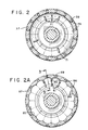
- FIGs 2A and 3 there is shown an alternative structure of the tube 71 and nozzle entry shown in Figures 1 and 2.
- tube 81 extends upward between nozzles 36 but quite close to the level of the nozzles and has a hood element 83 which extends to the nozzle level giving the tube a "cobra" configuration.
- the entry or portal portion of the nozzles 36 is in the form of scallops 85 so that the heavy fraction has a settling region or volume at the entry to the nozzles for accumulating material for ejection through the nozzles.
- the hooded aspect of the tubes 81 tends to concentrate the dilute mixed return flow at the scalloped portals so that the liquid associated with the feed flow and burdened with its high solubles content is displaced to overflow.
- Static mixing elements 80 may be provided in tubes 71 and 81 (as in Figure 3) to promote thorough mixing of wash liquid and return flow prior to injection into separating chamber 32.
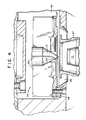
- FIGs 4 and 4A an alternative impeller structure 90 intended for a centrifuge of greater capacity than that illustrated in Figure 1.
- the impeller chamber 99 includes an impeller structure 90 comprising a hub cap 91 in which are secured a plurality of radial vanes 93 which have lifting surfaces 95 provided at the lower inner portion thereof. At the outer extremity of the vanes 93 the lower edge portions thereof are fixed as by welding or otherwise in a ring member 97 which is secured directly or indirectly to the rotor member 98.
- Figure 4A shows this impeller structure in perspective and it will be understood that this impeller structure rotates with the rotor structure of the centrifuge and receives return flow from nozzle 67 ( Figure 4) together with wash liquid from nozzle 75.
- the hub cap 91 guides this mixed flow into the spaces between the rotating vanes 93 and the lifting surfaces 95 on the vanes drive the mixed flow upward toward the tubes leading into the separating chamber of the centrifuge.
- Foam is very detrimental when handling fluid so provision must be made for reducing foam in the centrifuge by removing the gases which become associated with the feed, return flow and wash liquid of the process.
- the gas flows with the feed downward in feed passage 43 past the end of annular tube 44 at which point the gas rises along a narrow annular vent passage (not shown) about the exterior wall of annular tube 44 and passes into volute chamber 21.
- Chamber 21 or overflow conduit 28 or both are provided with vents (not shown) to discharge the gas.
- the gas introduced with the return flow or wash liquid and agitated in impeller chamber 55 is vented into housing 19 through passage 66 about the convergent nozzle 67. Housing 19 is provided with vent means (not shown) to discharge the gas.
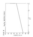
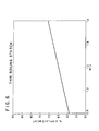
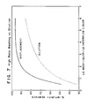
- Figure 7 shows curves developed from many tests using various feeds over a wide range of wash liquor/underflow liquor ratios.
- the two curves demonstrate the improvement in % impurity removed obtained by employing high-rate washing (displacement washing) as opposed to the dilution washing. It is seen that with displacement washing over 90% impurity removal is obtained at about a wash liquor/underflow liquor ratio of 3.
- Solids of the same type can also be classified by this high rate wash centrifuge process on the basis of size alone.
- the removal of kaolin particles of less than 0.25 microns from a mixture of kaolin clay particles ranging from 0.10 microns to 2.0 microns is effected using an upflow wash of 1.5 W/U in the centrifuge.
Landscapes
- Centrifugal Separators (AREA)
Applications Claiming Priority (2)
| Application Number | Priority Date | Filing Date | Title |
|---|---|---|---|
| US612044 | 1984-05-18 | ||
| US61204490A | 1990-11-13 | 1990-11-13 |
Publications (2)
| Publication Number | Publication Date |
|---|---|
| EP0486260A2 true EP0486260A2 (de) | 1992-05-20 |
| EP0486260A3 EP0486260A3 (en) | 1992-07-01 |
Family
ID=24451482
Family Applications (1)
| Application Number | Title | Priority Date | Filing Date |
|---|---|---|---|
| EP19910310427 Withdrawn EP0486260A3 (en) | 1990-11-13 | 1991-11-12 | High-rate washing centrifuge |
Country Status (19)
| Country | Link |
|---|---|
| EP (1) | EP0486260A3 (de) |
| JP (1) | JPH04284865A (de) |
| KR (1) | KR920009453A (de) |
| CN (1) | CN1061357A (de) |
| AU (1) | AU8015491A (de) |
| BR (1) | BR9104626A (de) |
| CA (1) | CA2044299A1 (de) |
| EG (1) | EG19480A (de) |
| FI (1) | FI915327L (de) |
| HU (1) | HUT61225A (de) |
| IE (1) | IE912540A1 (de) |
| IL (1) | IL98364A0 (de) |
| MA (1) | MA22309A1 (de) |
| MX (1) | MX9100748A (de) |
| NO (1) | NO914427L (de) |
| NZ (1) | NZ238772A (de) |
| PE (1) | PE29091A1 (de) |
| PT (1) | PT98723A (de) |
| ZA (1) | ZA914723B (de) |
Cited By (4)
| Publication number | Priority date | Publication date | Assignee | Title |
|---|---|---|---|---|
| US6475132B2 (en) | 2000-06-16 | 2002-11-05 | Westfalia Separator Food Tec Gmbh | Double-intake disk centrifuge |
| EP2566626B2 (de) † | 2010-05-03 | 2017-10-25 | GEA Mechanical Equipment GmbH | Düsenseparator und verfahren zum ableiten einer feststoffphase aus dem düsenseparator |
| WO2022263183A1 (de) * | 2021-06-17 | 2022-12-22 | Gea Westfalia Separator Group Gmbh | Zentrifugentrommel eines düsenseparators und düsenseparator |
| WO2024089209A1 (en) | 2022-10-27 | 2024-05-02 | Beneo Remy | Process for preparing starch having a reduced amount of contaminants |
Families Citing this family (1)
| Publication number | Priority date | Publication date | Assignee | Title |
|---|---|---|---|---|
| CN100418603C (zh) * | 2006-01-23 | 2008-09-17 | 吴庆元 | 球罐状分离装置 |
Family Cites Families (4)
| Publication number | Priority date | Publication date | Assignee | Title |
|---|---|---|---|---|
| US3073516A (en) * | 1959-08-06 | 1963-01-15 | Dorr Oliver Inc | Centrifuges |
| US3080108A (en) * | 1961-01-12 | 1963-03-05 | Dorr Oliver Inc | Centrifugal machines having a nozzle type rotor structure |
| SE335842B (de) * | 1966-12-21 | 1971-06-07 | Dorr Oliver Inc | |
| US3443746A (en) * | 1967-01-19 | 1969-05-13 | Dorr Oliver Inc | Counter-current wash for centrifugal separator |
-
1991
- 1991-06-04 IL IL98364A patent/IL98364A0/xx unknown
- 1991-06-11 CA CA002044299A patent/CA2044299A1/en not_active Abandoned
- 1991-06-19 ZA ZA914723A patent/ZA914723B/xx unknown
- 1991-06-20 HU HU912060A patent/HUT61225A/hu unknown
- 1991-06-28 NZ NZ238772A patent/NZ238772A/xx unknown
- 1991-07-02 AU AU80154/91A patent/AU8015491A/en not_active Abandoned
- 1991-07-03 MA MA22475A patent/MA22309A1/fr unknown
- 1991-07-15 EG EG43091A patent/EG19480A/xx active
- 1991-07-18 KR KR1019910012244A patent/KR920009453A/ko not_active Withdrawn
- 1991-07-19 IE IE254091A patent/IE912540A1/en unknown
- 1991-07-30 PE PE1991188926A patent/PE29091A1/es unknown
- 1991-08-20 MX MX9100748A patent/MX9100748A/es unknown
- 1991-08-20 PT PT98723A patent/PT98723A/pt not_active Application Discontinuation
- 1991-10-01 JP JP3280742A patent/JPH04284865A/ja active Pending
- 1991-10-25 BR BR919104626A patent/BR9104626A/pt not_active Application Discontinuation
- 1991-11-09 CN CN91110539A patent/CN1061357A/zh active Pending
- 1991-11-12 NO NO91914427A patent/NO914427L/no unknown
- 1991-11-12 EP EP19910310427 patent/EP0486260A3/en not_active Withdrawn
- 1991-11-12 FI FI915327A patent/FI915327L/fi not_active Application Discontinuation
Cited By (4)
| Publication number | Priority date | Publication date | Assignee | Title |
|---|---|---|---|---|
| US6475132B2 (en) | 2000-06-16 | 2002-11-05 | Westfalia Separator Food Tec Gmbh | Double-intake disk centrifuge |
| EP2566626B2 (de) † | 2010-05-03 | 2017-10-25 | GEA Mechanical Equipment GmbH | Düsenseparator und verfahren zum ableiten einer feststoffphase aus dem düsenseparator |
| WO2022263183A1 (de) * | 2021-06-17 | 2022-12-22 | Gea Westfalia Separator Group Gmbh | Zentrifugentrommel eines düsenseparators und düsenseparator |
| WO2024089209A1 (en) | 2022-10-27 | 2024-05-02 | Beneo Remy | Process for preparing starch having a reduced amount of contaminants |
Also Published As
| Publication number | Publication date |
|---|---|
| MA22309A1 (fr) | 1992-07-01 |
| KR920009453A (ko) | 1992-06-25 |
| BR9104626A (pt) | 1992-06-23 |
| IL98364A0 (en) | 1992-07-15 |
| JPH04284865A (ja) | 1992-10-09 |
| FI915327A0 (fi) | 1991-11-12 |
| FI915327A7 (fi) | 1992-05-14 |
| MX9100748A (es) | 1992-07-08 |
| IE912540A1 (en) | 1992-05-20 |
| EP0486260A3 (en) | 1992-07-01 |
| PT98723A (pt) | 1993-09-30 |
| FI915327L (fi) | 1992-05-14 |
| HUT61225A (en) | 1992-12-28 |
| ZA914723B (en) | 1993-02-24 |
| HU912060D0 (en) | 1991-12-30 |
| CN1061357A (zh) | 1992-05-27 |
| CA2044299A1 (en) | 1992-05-14 |
| AU8015491A (en) | 1992-05-14 |
| NZ238772A (en) | 1993-09-27 |
| PE29091A1 (es) | 1991-10-07 |
| EG19480A (en) | 1995-04-30 |
| NO914427L (no) | 1992-05-14 |
| NO914427D0 (no) | 1991-11-12 |
Similar Documents
| Publication | Publication Date | Title |
|---|---|---|
| US5407584A (en) | Water clarification method | |
| US4216095A (en) | Dynamic dense media separator | |
| CA2065153C (en) | Orbital separator and method of orbitally separating a mixture | |
| JP3848372B2 (ja) | 液体から固体粒子を不連続に分離するための装置及び方法 | |
| US20110003676A1 (en) | A separation device | |
| US4451247A (en) | Continuous, completely jacketed, countercurrent centrifugal extractor | |
| US4362536A (en) | Pulp degassing | |
| US4252640A (en) | Apparatus for sorting fibrous stock suspensions | |
| JPH01270913A (ja) | 活性スラッジを含んだ排水の懸濁液から活性スラッジを分離するために使用される沈澱タンク | |
| CN211660259U (zh) | 一种立式离心机 | |
| EP0486260A2 (de) | Hochleistungswaschzentrifuge | |
| US2958461A (en) | Centrifuge machine | |
| CN211246968U (zh) | 一种液液固离心机 | |
| CN1005822B (zh) | 萃取过程中使两相分散的方法和实现该方法的设备 | |
| US5823937A (en) | Low-shear feeding system for use with centrifuges | |
| US4806019A (en) | Method and apparatus for mixing two or more components such as immiscible liquids | |
| US20210023478A1 (en) | Single stage clarifier and mixing assembly | |
| WO1997016256A9 (en) | Low-shear centrifuge feeding system | |
| EP0606716B1 (de) | Verfahren und Vorrichtung zur Phasentrennung | |
| US4365741A (en) | Continuous centrifugal separation of coal from sulfur compounds and mineral impurities | |
| EP0069119A4 (de) | Rückgewinnungssystem für flüssigkeiten. | |
| US3406825A (en) | Centripetal separation method and apparatus | |
| US2551820A (en) | Extraction column | |
| KR102745417B1 (ko) | 분리판형 원심분리기 및 분리판형 원심분리기용 층류형성장치 | |
| US11596912B2 (en) | Single stage clarifier and mixing assembly |
Legal Events
| Date | Code | Title | Description |
|---|---|---|---|
| PUAI | Public reference made under article 153(3) epc to a published international application that has entered the european phase |
Free format text: ORIGINAL CODE: 0009012 |
|
| PUAL | Search report despatched |
Free format text: ORIGINAL CODE: 0009013 |
|
| AK | Designated contracting states |
Kind code of ref document: A2 Designated state(s): AT BE CH DE DK ES FR GB GR IT LI LU NL SE |
|
| AK | Designated contracting states |
Kind code of ref document: A3 Designated state(s): AT BE CH DE DK ES FR GB GR IT LI LU NL SE |
|
| 17P | Request for examination filed |
Effective date: 19921218 |
|
| 17Q | First examination report despatched |
Effective date: 19931202 |
|
| STAA | Information on the status of an ep patent application or granted ep patent |
Free format text: STATUS: THE APPLICATION IS DEEMED TO BE WITHDRAWN |
|
| 18D | Application deemed to be withdrawn |
Effective date: 19951003 |