EP0486330A1 - Verbesserter Bürstenhalter für Kollektormotoren - Google Patents
Verbesserter Bürstenhalter für Kollektormotoren Download PDFInfo
- Publication number
- EP0486330A1 EP0486330A1 EP91402468A EP91402468A EP0486330A1 EP 0486330 A1 EP0486330 A1 EP 0486330A1 EP 91402468 A EP91402468 A EP 91402468A EP 91402468 A EP91402468 A EP 91402468A EP 0486330 A1 EP0486330 A1 EP 0486330A1
- Authority
- EP
- European Patent Office
- Prior art keywords
- brush holder
- shells
- brush
- plate
- holder according
- Prior art date
- Legal status (The legal status is an assumption and is not a legal conclusion. Google has not performed a legal analysis and makes no representation as to the accuracy of the status listed.)
- Granted
Links
- 229920003002 synthetic resin Polymers 0.000 claims description 3
- 239000000057 synthetic resin Substances 0.000 claims description 3
- 230000002093 peripheral effect Effects 0.000 claims description 2
- 238000000034 method Methods 0.000 description 3
- OKTJSMMVPCPJKN-UHFFFAOYSA-N Carbon Chemical compound [C] OKTJSMMVPCPJKN-UHFFFAOYSA-N 0.000 description 2
- 244000007853 Sarothamnus scoparius Species 0.000 description 2
- 238000004026 adhesive bonding Methods 0.000 description 2
- 229910052799 carbon Inorganic materials 0.000 description 2
- 239000000470 constituent Substances 0.000 description 2
- 239000000463 material Substances 0.000 description 2
- 238000013021 overheating Methods 0.000 description 2
- 230000005855 radiation Effects 0.000 description 2
- 238000009423 ventilation Methods 0.000 description 2
- 238000003466 welding Methods 0.000 description 2
- 229910001369 Brass Inorganic materials 0.000 description 1
- 238000005452 bending Methods 0.000 description 1
- 239000010951 brass Substances 0.000 description 1
- 230000008094 contradictory effect Effects 0.000 description 1
- 230000002950 deficient Effects 0.000 description 1
- 230000000694 effects Effects 0.000 description 1
- 238000010438 heat treatment Methods 0.000 description 1
- 239000011810 insulating material Substances 0.000 description 1
- 238000000465 moulding Methods 0.000 description 1
- BASFCYQUMIYNBI-UHFFFAOYSA-N platinum Chemical compound [Pt] BASFCYQUMIYNBI-UHFFFAOYSA-N 0.000 description 1
- 230000035939 shock Effects 0.000 description 1
- 238000004804 winding Methods 0.000 description 1
Images

Classifications
-
- H—ELECTRICITY
- H01—ELECTRIC ELEMENTS
- H01R—ELECTRICALLY-CONDUCTIVE CONNECTIONS; STRUCTURAL ASSOCIATIONS OF A PLURALITY OF MUTUALLY-INSULATED ELECTRICAL CONNECTING ELEMENTS; COUPLING DEVICES; CURRENT COLLECTORS
- H01R39/00—Rotary current collectors, distributors or interrupters
- H01R39/02—Details for dynamo electric machines
- H01R39/38—Brush holders
- H01R39/40—Brush holders enabling brush movement within holder during current collection
Definitions
- the present invention relates to direct current electric motors, the switching of which is ensured by a collector and brushes elastically urged against it, and more particularly relates to a brush holder intended to be mounted on a plate associated with the stator. such an electric motor.
- DC electric motors are used, the switching of which is ensured by a collector and brushes elastically biased against the latter. This is for example the case in the automotive industry where such motors are commonly in use for driving windshield wipers, maneuvering window regulators or driving motorized fans.
- the collector is usually placed at the end of the shaft so that the plate with which the brush holders are associated most often only increases the overall length of the stator of such a motor.
- a brush holder is for example exposed in the document FR 1 522 538.
- the solution proposed is far from satisfactory.
- the object of the invention is to remedy most of the drawbacks briefly recalled above using a brush holder for a DC electric motor plate, the switching of which is ensured by a collector and brushes elastically urged against it.
- collector which is designed to be mounted on the plate and to receive a brush in order to minimize the risks of jamming of the brush in the brush holder during the operation of the motor, to allow a good ventilation and also to reduce the axial dimensions of an engine.
- the subject of the invention is a brush holder for a DC electric motor plate, the switching of which is ensured by a collector and brushes elastically urged against this collector.
- This brush holder which is intended to be mounted on the plate and to receive a brush is remarkable in that it comprises a hollow chimney with polygonal cross section with two projecting lateral wings, which is made up of two U-shaped half-shells composed , each of two opposite branches which are connected by a bridge and which each have a rim practically parallel to this bridge and directed in the opposite direction.
- This brush holder is also remarkable in that the distance between two opposite branches of one of the half-shells, measured near the corresponding bridge, is greater than this same distance from the other of the half-shells, these half-shells shells being joined by their edges so as to constitute this chimney and so that at least two of these edges constitute the wings and form in part a device for mounting the brush holder on the plate.
- a direct current electric motor usually comprises a stator consisting of a central carcass and end flanges with bearings. It also includes a rotor with a shaft carried by these bearings and on which a collector is mounted. All this is classic and for this not shown, nor described more fully.
- Such a motor usually comprises a brush holder plate 10 connected to the stator by appropriate fixing means and often close to one of the end flanges.
- a plate is practically plumb or in the immediate vicinity of the collector.
- the plate 10 is conventionally in the form of a plate 100 pierced with an aperture 101 for the passage of the shaft and / or the manifold, as well as at least one recess 102 intended to receive a brush holder 11 which is mounted therein using a mounting device 103.
- the plate 10 is also intended to further receive brushes 12, or coals, which are usually in the form of sticks 120 of circular or polygonal cross section which are able to move freely in the brush holders 11 which receive them.
- An elastic biasing member 13 acts on each brush 12 in order to make it slide in the brush holder in the radial direction and in the centripetal direction so as to apply it closely against the collector.
- a suitable electrical connection connects this brush or carbon to the rest of the electrical circuit of the motor, as is well known.
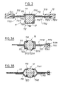
- a brush holder 11 according to the invention is in the manner of a hollow chimney 110 with two projecting lateral wings 1100, as illustrated.
- This chimney as it appears in Figures 2, 3A and 3B, has a polygonal cross section and preferably quadrangular or hexagonal.
- the chimney 110 is made up of two half-shells 111 and 112 in a U shape.
- each of the two half-shells 111 and 112 is made up of two opposite branches 1111 and 1121, respectively, which are connected by a bridge 1112 and 1122 respectively.
- Each of the branches is also provided with a flange 1113 and 1123, respectively, which is practically parallel to the corresponding bridge and directed in the opposite direction.
- the distance between two opposite branches of one of the half-shells, measured near the corresponding bridge, is greater than this same distance from the other of the half-shells.
- these half-shells are joined by their edges so as to constitute this chimney and so that at least two of these edges constitute the wings and form in part the mounting device 103 of the door -broom on the stage, as will be understood later.
- the technique used to join the two half-shells by their edges is common.
- the cross section of the chimney is then quadrangular.
- the cross section of the chimney is then for example hexagonal.
- the recess 102 is delimited by two opposite sections 1020 in each of which a groove 1030 is hollowed out.
- This groove constitutes a part of the mounting device 103.
- the other part of this mounting device 103 is constituted by the margin 1114, 1124 d a flange 1113, 1123 which serves as a tongue and which is intended to be engaged in the groove 1030.
- one of the branches 1111 has a slot 113 oriented practically parallel to the bridge 1112, and intended for the passage of a member for the elastic stress of a brush, member which is, for example, in the form of a hairpin spring.
- the elastic biasing member is in the form of a coil spring which is inserted in the chimney 110 so that one of its ends bears on the chimney opposite the collector and that the other of its ends rests on the broom.
- a stick-shaped broom 120 is used, for example with an approximately square cross section which is provided with at least one axial peripheral promontory 1201 with edges 1202.
- one at less of the bridges 1112 is arranged so as to present a clearance 114 with sides 1141 practically parallel to a corresponding branch 1141 and intended for the passage of this promontory.
- the sides 1141 of the clearance cooperate with the edges 1202 of the headland of the brush to guide it.
- the width of the openings is different so that only the flanks of one of them guide and effectively direct the corresponding edges 1202 of a promotion.
- the size of the recesses and their judicious arrangement allow the brush holders to be left free, practically on all sides, and to give them a large accessible surface. In this way, the brush holders can be easily ventilated and dissipate calories by radiation in particular.
- a brush holder is used, at least one of the two shells of which is metallic, for example made of brass board or the like which is made up by conventional cutting, stamping and bending, folding operations.
- the plate is made of a synthetic resin obtained for example by molding.
Landscapes
- Motor Or Generator Current Collectors (AREA)
- Current-Collector Devices For Electrically Propelled Vehicles (AREA)
- Motor Or Generator Frames (AREA)
Applications Claiming Priority (2)
| Application Number | Priority Date | Filing Date | Title |
|---|---|---|---|
| FR9014075 | 1990-11-13 | ||
| FR9014075A FR2669160B1 (fr) | 1990-11-13 | 1990-11-13 | Porte-balai perfectionne pour moteur electrique a collecteur. |
Publications (2)
| Publication Number | Publication Date |
|---|---|
| EP0486330A1 true EP0486330A1 (de) | 1992-05-20 |
| EP0486330B1 EP0486330B1 (de) | 1995-06-14 |
Family
ID=9402127
Family Applications (1)
| Application Number | Title | Priority Date | Filing Date |
|---|---|---|---|
| EP19910402468 Expired - Lifetime EP0486330B1 (de) | 1990-11-13 | 1991-09-17 | Verbesserter Bürstenhalter für Kollektormotoren |
Country Status (4)
| Country | Link |
|---|---|
| EP (1) | EP0486330B1 (de) |
| DE (1) | DE69110408T2 (de) |
| ES (1) | ES2073702T3 (de) |
| FR (1) | FR2669160B1 (de) |
Cited By (1)
| Publication number | Priority date | Publication date | Assignee | Title |
|---|---|---|---|---|
| FR2911016A1 (fr) * | 2006-11-30 | 2008-07-04 | Valeo Equip Electr Moteur | Ensemble cage de guidage et balai pour un porte-balais et machine electrique comportant un porte-balais avec un tel ensemble. |
Families Citing this family (3)
| Publication number | Priority date | Publication date | Assignee | Title |
|---|---|---|---|---|
| US6133665A (en) * | 1998-08-14 | 2000-10-17 | S-B Power Tool Company | Brush system for electric motors |
| DE102008041717A1 (de) * | 2008-08-29 | 2010-03-04 | Robert Bosch Gmbh | Handwerkzeugmaschine mit Bürstenmotor |
| DE102014225520A1 (de) * | 2014-12-11 | 2016-06-30 | Robert Bosch Gmbh | Kommutierungseinrichtung für eine elektrische Maschine |
Citations (2)
| Publication number | Priority date | Publication date | Assignee | Title |
|---|---|---|---|---|
| FR2582872A1 (fr) * | 1985-05-30 | 1986-12-05 | Peugeot Aciers Et Outillage | Plaque porte-balais perfectionnee pour moteur electrique et son procede de fabrication |
| FR2631176A1 (fr) * | 1988-05-04 | 1989-11-10 | Valeo | Dispositif porte-balais pour machine tournante electrique |
-
1990
- 1990-11-13 FR FR9014075A patent/FR2669160B1/fr not_active Expired - Lifetime
-
1991
- 1991-09-17 DE DE1991610408 patent/DE69110408T2/de not_active Expired - Fee Related
- 1991-09-17 ES ES91402468T patent/ES2073702T3/es not_active Expired - Lifetime
- 1991-09-17 EP EP19910402468 patent/EP0486330B1/de not_active Expired - Lifetime
Patent Citations (2)
| Publication number | Priority date | Publication date | Assignee | Title |
|---|---|---|---|---|
| FR2582872A1 (fr) * | 1985-05-30 | 1986-12-05 | Peugeot Aciers Et Outillage | Plaque porte-balais perfectionnee pour moteur electrique et son procede de fabrication |
| FR2631176A1 (fr) * | 1988-05-04 | 1989-11-10 | Valeo | Dispositif porte-balais pour machine tournante electrique |
Cited By (1)
| Publication number | Priority date | Publication date | Assignee | Title |
|---|---|---|---|---|
| FR2911016A1 (fr) * | 2006-11-30 | 2008-07-04 | Valeo Equip Electr Moteur | Ensemble cage de guidage et balai pour un porte-balais et machine electrique comportant un porte-balais avec un tel ensemble. |
Also Published As
| Publication number | Publication date |
|---|---|
| FR2669160B1 (fr) | 1993-02-19 |
| DE69110408D1 (de) | 1995-07-20 |
| FR2669160A1 (fr) | 1992-05-15 |
| EP0486330B1 (de) | 1995-06-14 |
| ES2073702T3 (es) | 1995-08-16 |
| DE69110408T2 (de) | 1995-11-02 |
Similar Documents
| Publication | Publication Date | Title |
|---|---|---|
| EP0991162B1 (de) | Wechselstromgenerator für Kraftfahrzeuge mit Vorrichtung zur Spielbeseitigung von Zwischenpol-Magneten | |
| EP1277030B1 (de) | Magnetfluss-konzentrierender verbinder für elektrische motoren | |
| EP0743738B1 (de) | Gleichstromgenerator, insbesondere für Kraftfahrzeug, der eine verbesserte Anordnung für Gleichrichtungsdioden enthält | |
| EP2830179A2 (de) | Elektrisch umlaufende Maschine, entsprechende Halterung für Temperatursonde und entsprechende Temperaturmesseinheit | |
| FR3121988A1 (fr) | Dispositif de mesure de température destiné à mesurer la température d’une broche d’un connecteur électrique | |
| EP0282377B1 (de) | Elektrische Motorgetriebeeinheit und Verfahren zu deren Montage | |
| EP0486330B1 (de) | Verbesserter Bürstenhalter für Kollektormotoren | |
| FR2675322A1 (fr) | Micromoteur electromagnetique a flux axial. | |
| FR3037381A1 (fr) | Dispositif de positionnement d'un support lumineux d'une diode electroluminescente sur un element support et module lumineux pour dispositif d'eclairage et/ou de signalisation comportant un tel dispositif | |
| EP0898807B1 (de) | Kollektorgehäuse-und motorgetriebeanschlusseinheit | |
| WO2015150672A2 (fr) | Platine support de porte-balais pour moteur electrique et porte-balai correspondant | |
| FR2902872A1 (fr) | Dispositif de mesure de champ magnetique. | |
| FR3056844A1 (fr) | Moteur electrique a courant continu sans balais pour systeme d'essuyage de vehicule automobile | |
| WO2024121480A1 (fr) | Guide de connecteurs pour onduleur comportant un organe de plaquage | |
| EP1331126B1 (de) | Hybridantriebssystem eines Kraftfahrzeugs mit elastischer Kupplungsvorrichtung zwischen dem Rotor der reversiblen elektrischen Maschine und der Antriebswelle des Schaltgetriebes des Kraftfahrzeugs | |
| EP0771414B1 (de) | Vorrichtung zum messen des drehmoments | |
| EP0743740B1 (de) | Wechselstromgenerator, insbesondere für Kraftwagen, mit einer Gleichrichterdiodenanordnung | |
| EP3474025A1 (de) | Messfühler zum messen des ausgangsstroms eines elektrischen systems | |
| FR2585409A1 (fr) | Dispositif d'actionnement electrique d'un organe, notamment d'un volet de papillon de carburateur | |
| FR2950011A1 (fr) | Dispositif d'entrainement d'essuie-glace equipe d'une installation de determination de position | |
| FR2513036A1 (fr) | Generatrice a courant triphase sans collecteur a friction | |
| FR3142625A1 (fr) | Dispositif de mise à une masse d’un rotor, machine électrique et véhicule automobile associé | |
| EP1901397A2 (de) | Elektrische Verbindungseinrichtung | |
| EP0223678A1 (de) | Elektronisch kommutierter Gleichstrommotor | |
| FR3039938A1 (fr) | Ensemble pour machine electrique tournante comportant un collecteur fixe au moyen d'une goupille |
Legal Events
| Date | Code | Title | Description |
|---|---|---|---|
| PUAI | Public reference made under article 153(3) epc to a published international application that has entered the european phase |
Free format text: ORIGINAL CODE: 0009012 |
|
| 17P | Request for examination filed |
Effective date: 19920320 |
|
| AK | Designated contracting states |
Kind code of ref document: A1 Designated state(s): DE ES GB IT SE |
|
| 17Q | First examination report despatched |
Effective date: 19940415 |
|
| GRAA | (expected) grant |
Free format text: ORIGINAL CODE: 0009210 |
|
| AK | Designated contracting states |
Kind code of ref document: B1 Designated state(s): DE ES GB IT SE |
|
| ITF | It: translation for a ep patent filed | ||
| REF | Corresponds to: |
Ref document number: 69110408 Country of ref document: DE Date of ref document: 19950720 |
|
| REG | Reference to a national code |
Ref country code: ES Ref legal event code: FG2A Ref document number: 2073702 Country of ref document: ES Kind code of ref document: T3 |
|
| GBT | Gb: translation of ep patent filed (gb section 77(6)(a)/1977) |
Effective date: 19950921 |
|
| PLBE | No opposition filed within time limit |
Free format text: ORIGINAL CODE: 0009261 |
|
| STAA | Information on the status of an ep patent application or granted ep patent |
Free format text: STATUS: NO OPPOSITION FILED WITHIN TIME LIMIT |
|
| 26N | No opposition filed | ||
| PGFP | Annual fee paid to national office [announced via postgrant information from national office to epo] |
Ref country code: DE Payment date: 19960821 Year of fee payment: 6 |
|
| PGFP | Annual fee paid to national office [announced via postgrant information from national office to epo] |
Ref country code: GB Payment date: 19960910 Year of fee payment: 6 |
|
| PGFP | Annual fee paid to national office [announced via postgrant information from national office to epo] |
Ref country code: ES Payment date: 19960917 Year of fee payment: 6 |
|
| PGFP | Annual fee paid to national office [announced via postgrant information from national office to epo] |
Ref country code: SE Payment date: 19960920 Year of fee payment: 6 |
|
| PG25 | Lapsed in a contracting state [announced via postgrant information from national office to epo] |
Ref country code: GB Free format text: LAPSE BECAUSE OF NON-PAYMENT OF DUE FEES Effective date: 19970917 |
|
| PG25 | Lapsed in a contracting state [announced via postgrant information from national office to epo] |
Ref country code: SE Free format text: LAPSE BECAUSE OF NON-PAYMENT OF DUE FEES Effective date: 19970918 Ref country code: ES Free format text: LAPSE BECAUSE OF EXPIRATION OF PROTECTION Effective date: 19970918 |
|
| GBPC | Gb: european patent ceased through non-payment of renewal fee |
Effective date: 19970917 |
|
| PG25 | Lapsed in a contracting state [announced via postgrant information from national office to epo] |
Ref country code: DE Free format text: LAPSE BECAUSE OF NON-PAYMENT OF DUE FEES Effective date: 19980603 |
|
| EUG | Se: european patent has lapsed |
Ref document number: 91402468.2 |
|
| REG | Reference to a national code |
Ref country code: ES Ref legal event code: FD2A Effective date: 20010201 |
|
| PG25 | Lapsed in a contracting state [announced via postgrant information from national office to epo] |
Ref country code: IT Free format text: LAPSE BECAUSE OF NON-PAYMENT OF DUE FEES;WARNING: LAPSES OF ITALIAN PATENTS WITH EFFECTIVE DATE BEFORE 2007 MAY HAVE OCCURRED AT ANY TIME BEFORE 2007. THE CORRECT EFFECTIVE DATE MAY BE DIFFERENT FROM THE ONE RECORDED. Effective date: 20050917 |