EP0486406A1 - Boîtier de protection d'un automate industriel - Google Patents
Boîtier de protection d'un automate industriel Download PDFInfo
- Publication number
- EP0486406A1 EP0486406A1 EP91420395A EP91420395A EP0486406A1 EP 0486406 A1 EP0486406 A1 EP 0486406A1 EP 91420395 A EP91420395 A EP 91420395A EP 91420395 A EP91420395 A EP 91420395A EP 0486406 A1 EP0486406 A1 EP 0486406A1
- Authority
- EP
- European Patent Office
- Prior art keywords
- automaton
- housing
- cradle
- casing
- protective
- Prior art date
- Legal status (The legal status is an assumption and is not a legal conclusion. Google has not performed a legal analysis and makes no representation as to the accuracy of the status listed.)
- Withdrawn
Links
- 230000001681 protective effect Effects 0.000 title claims abstract description 11
- 238000001816 cooling Methods 0.000 claims abstract description 7
- 230000035939 shock Effects 0.000 claims description 12
- 239000002184 metal Substances 0.000 claims description 7
- 239000006096 absorbing agent Substances 0.000 claims description 6
- 238000009413 insulation Methods 0.000 claims description 3
- 244000045947 parasite Species 0.000 claims description 3
- 238000000605 extraction Methods 0.000 claims description 2
- 238000004519 manufacturing process Methods 0.000 claims description 2
- 238000010438 heat treatment Methods 0.000 claims 1
- 230000001737 promoting effect Effects 0.000 abstract 1
- 230000005540 biological transmission Effects 0.000 description 2
- 239000000428 dust Substances 0.000 description 2
- 238000013016 damping Methods 0.000 description 1
- 230000005672 electromagnetic field Effects 0.000 description 1
- 238000009432 framing Methods 0.000 description 1
- 238000002955 isolation Methods 0.000 description 1
- 238000013021 overheating Methods 0.000 description 1
- 238000007789 sealing Methods 0.000 description 1
- 238000000926 separation method Methods 0.000 description 1
Images

Classifications
-
- B—PERFORMING OPERATIONS; TRANSPORTING
- B25—HAND TOOLS; PORTABLE POWER-DRIVEN TOOLS; MANIPULATORS
- B25H—WORKSHOP EQUIPMENT, e.g. FOR MARKING-OUT WORK; STORAGE MEANS FOR WORKSHOPS
- B25H3/00—Storage means or arrangements for workshops facilitating access to, or handling of, work tools or instruments
-
- H—ELECTRICITY
- H05—ELECTRIC TECHNIQUES NOT OTHERWISE PROVIDED FOR
- H05K—PRINTED CIRCUITS; CASINGS OR CONSTRUCTIONAL DETAILS OF ELECTRIC APPARATUS; MANUFACTURE OF ASSEMBLAGES OF ELECTRICAL COMPONENTS
- H05K7/00—Constructional details common to different types of electric apparatus
- H05K7/20—Modifications to facilitate cooling, ventilating, or heating
- H05K7/20009—Modifications to facilitate cooling, ventilating, or heating using a gaseous coolant in electronic enclosures
- H05K7/20136—Forced ventilation, e.g. by fans
- H05K7/20145—Means for directing air flow, e.g. ducts, deflectors, plenum or guides
-
- H—ELECTRICITY
- H05—ELECTRIC TECHNIQUES NOT OTHERWISE PROVIDED FOR
- H05K—PRINTED CIRCUITS; CASINGS OR CONSTRUCTIONAL DETAILS OF ELECTRIC APPARATUS; MANUFACTURE OF ASSEMBLAGES OF ELECTRICAL COMPONENTS
- H05K7/00—Constructional details common to different types of electric apparatus
- H05K7/14—Mounting supporting structure in casing or on frame or rack
- H05K7/1462—Mounting supporting structure in casing or on frame or rack for programmable logic controllers [PLC] for automation or industrial process control
- H05K7/1467—PLC mounted in a cabinet or chassis
Definitions
- the invention relates to a protective casing for an electronic device, in particular an automaton for controlling an industrial process or an automaton aboard a ship, or a land vehicle against shocks, external parasites and overheating, comprising a sealed metallic envelope inside which is fixed by mechanical dampers said automaton, providing an isolation gap between the housing and the automaton.
- the invention is based on the observation that today there are ranges of products specifically designed for use in an industrial environment and other products dedicated to exceptional ambient conditions, such as on board military land or naval vehicles.
- Standard devices are unable to function properly when subjected to mechanical shock and vibration, as well as dust pollution that quickly destroys or damages electronic components. Electromagnetic interference generated by neighboring electrical devices, or by the network, also disturb the proper functioning of electronic devices. On the other hand, dedicated hardware is often too expensive for non-vital applications.
- the object of the present invention is to provide a particularly simple and effective protective housing, allowing the use of a standard electronic device in a disturbed environment, in particular in an industrial environment.
- the protective housing according to the invention is characterized in that a fan, disposed in the sealed housing, causes air circulation in said gap inside the housing to standardize the temperature in the latter, and improve cooling by the external metallic envelope.
- the air circulation induced by the fan in the insulation gap between the electronic device, later called a controller, and the housing promotes cooling by convection of the controller, the heat being transmitted to the metal casing of the housing, which transmits this heat to the ambient environment.
- the internal circulation of air does not affect the tightness of the housing and favors the uniformity of the temperature of the PLC.
- the box advantageously includes connectors for the input and output cables of the automaton, which are arranged in sealed feedthroughs and in electrical filters preventing the transmission of disturbances and parasites inside the box.
- the metal casing and filter connectors ensure electromagnetic compatibility and allow the use of the PLC in electrically disturbed environments.
- a support cradle for example metallic, to which the internal circulation fan or fans is rigidly attached.
- the cradle is itself fixed to the housing by shock absorbers, providing an air gap around the entire periphery of the automaton, which prevents any mechanical contact with the wall of the housing.
- the shape of the protective case corresponds substantially to that of the automaton, but it is clear that a housing can be designed for a range of automatons of different sizes, the volume being in some cases overabundant .
- One of the faces of the box generally of rectangular shape, is arranged in a removable cover which gives access, after removal, to the shock absorber fixing bolts and to the wiring connectors, to allow mechanical and electrical disconnection of the automaton and an extraction of the latter.
- an automaton 10 represented by its parallelepipedic external contour, is housed inside a housing 11 of conjugate shape.
- the dimensions of the housing 11 are greater than those of the automaton 10, so as to provide on all sides, a gap 12 avoiding any mechanical contact between the automaton 10 and the housing 11.
- the housing 11 made of sheet metal is closed with a sealed manner at its upper face by a metal plate 13, fixed by bolts 14, to constitute a cover giving access to the interior of a housing after removal.
- the opposite bottom 15 can also be arranged in a removable plate constituting the base for fixing the housing.
- the front face of the housing 11 has an appendage 16 having an inclined face 17 carrying connectors 18.
- the automaton 10 is rigidly secured by bolts 20 to a cradle 19, produced by profiles or sheets framing the automaton 10 on all of these faces, except that facing the cover 13.
- the cradle 19 is extended on the side of the front face by a support 21 of two fans 32.
- the cradle 19 is itself fixed to the casing of the housing 11 by dampers 22 made up of two fixing plates 23, 24, connected by elastic braids 25.
- the dampers 22 can of course be of any type, their arrangement and their number being sufficient to resiliently position the assembly inside the housing 11 while avoiding any mechanical contact between the automaton 10 and the housing 11, and by damping the shocks and vibrations liable to be transmitted by the housing 11 to the automaton 10.
- the use of a cradle 19 allows an appropriate arrangement of the dampers 22 , this arrangement being completely independent of the standard means for fixing the automaton 10.
- the automaton 10 assembly, cradle 19 and fan 32 constitutes an assembly or block capable of being extracted from the housing 11 after removal of the cover 13 and disconnection of the shock absorbers 22.
- the connectors 18 are connected by a wiring 26 to the terminal block (not shown) of the controller 10, and this wiring must of course also be disconnected during 'A separation of the controller 10 from the housing 11.
- the connectors 18 which are inputs and outputs of the controller, as well as the power supplies of the latter are, if necessary, arranged in electrical filters, well known per se, preventing any transmission of noise to PLC 10 or vice versa to the outside.
- the controller 10 is separated from the housing 11 by the air gap 12, and the only connections by the shock absorbers 22 and the wiring 26 are unable to transmit to the controller 10 shocks or other harmful disturbances.
- the fan (s) 32 provide air circulation inside the housing 11, in particular in the interval 12 which ensures uniformity of the temperature inside the housing 11, and circulation between the automatic device 10, or more particularly the hot parts of the machine 10, and the metal casing of the housing 11. This air circulation prevents the gap 12 constituting thermal insulation preventing effective cooling of the machine 10. This cooling is carried out without continuity solution of the sealing of the housing 11, which avoids any risk of interference or pollution access to the controller 10.
- the degree of protection can be adapted to the conditions of use, but in all cases, the means of implementation are simple and inexpensive.
- the fan 32 can also be fixed to the casing of the housing 11, or that the cradle 19 can be simplified and be arranged in a simple frame extending between the fixing points of the shock absorbers 22 and those of the automaton 10.
- the housing according to the invention has the advantage of being adaptable to all types of electronic devices or automata, and of being usable if necessary with a range of devices whose shapes are not necessarily rectangular.
Landscapes
- Engineering & Computer Science (AREA)
- Microelectronics & Electronic Packaging (AREA)
- Physics & Mathematics (AREA)
- Thermal Sciences (AREA)
- Automation & Control Theory (AREA)
- Mechanical Engineering (AREA)
- Casings For Electric Apparatus (AREA)
- Cooling Or The Like Of Electrical Apparatus (AREA)
Abstract
Un automate (10) est fixé à l'intérieur d'un boîtier (11) de protection, par l'intermédiaire d'amortisseurs (22), en ménageant un intervalle d'air (12). Le boîtier étanche (11) assure une protection mécanique et électrique de l'automate (10), et un ventilateur (32) logé dans le boîtier (11) provoque une circulation d'air favorisant le refroidissement de l'automate (10). Des connecteurs agencés en filtres électriques sont fixés sur la paroi du boîtier étanche (11). <IMAGE>
Description
- L'invention est relative à un boîtier de protection d'un appareil électronique en particulier d'un automate de commande d'un processus industriel ou d'un automate à bord d'un navire, ou d'un véhicule terrestre contre les chocs, les parasites extérieurs et l'échauffement, comprenant une enveloppe étanche métallique à l'intérieur de laquelle est fixé par des amortisseurs mécaniques ledit automate, en ménageant un intervalle d'isolation entre le boîtier et l'automate.
- L'invention est basée sur la constatation qu'il existe aujourd'hui des gammes de produits spécifiquement conçus pour une utilisation en milieu industriel et d'autres produits dédiés aux conditions ambiantes exceptionnelles, telles qu'à bord de véhicules militaires terrestres ou navals.
- Les appareils standards sont incapables de fonctionner correctement quand ils sont soumis à des chocs et des vibrations mécaniques, ainsi qu'à une pollution par des poussières qui détruisent ou détériorent rapidement les composants électroniques. Les parasites électromagnétiques engendrés par les appareils électriques voisins, ou par le réseau, perturbent également le bon fonctionnement des appareils électroniques. D'autre part, les matériels dédiés sont souvent d'un coût trop élevé pour des applications non vitales.
- En disposant l'appareil électronique ou l'automate industriel dans un coffret métallique étanche, il est possible de s'affranchir des chocs et des poussières, et partiellement de l'influence des champs magnétiques et électromagnétiques ambiants, mais le refroidissement de l'appareil est entravé par ce coffret étanche.
- La présente invention a pour but de réaliser un boîtier de protection, particulièrement simple et efficace, permettant l'utilisation d'un appareil électronique standard en un milieu perturbé, notamment en un milieu industriel.
- Le boîtier de protection selon l'invention est caractérisé en ce qu'un ventilateur, disposé dans le boîtier étanche, provoque une circulation de l'airdans ledit intervalle à l'intérieur du boîtier pour uniformiser la température dans ce dernier, et améliorer le refroidissement par l'enveloppe métallique externe.
- La circulation d'air induite par le ventilateur dans l'intervalle d'isolation entre l'appareil électronique, appelé automate par la suite, et le boîtier favorise un refroidissement par convection de l'automate, la chaleur étant transmise à l'enveloppe métallique du boîtier, qui transmet cette chaleur au milieu ambiant.
- La circulation interne de l'air n'affecte pas l'étanchéité du boîtier et favorise l'homogénéité de la température de l'automate.
- Le boîtier comporte avantageusement des connecteurs des câbles d'entrée et de sortie de l'automate, qui sont agencés en traversées étanches et en filtres électriques empêchant la transmission des perturbations et parasites à l'intérieur du boîtier. L'enveloppe métallique et les connecteurs filtres assurent la compatibilité électromagnétique et permettent l'utilisation de l'automate en des milieux électriquement perturbés.
- Il est avantageux de fixer l'automate standard à un berceau de support, par exemple métallique, auquel est assujetti rigidement le ou les ventilateurs de circulation interne d'air. Le berceau est lui-même fixé au boîtier par des amortisseurs en ménageant un intervalle d'air sur l'ensemble du pourtour de l'automate, qui empêche tout contact mécanique avec la paroi du boîtier. Pour des raisons d'encombrement, la forme du boîtier de protection correspond sensiblement à celle de l'automate, mais il est clair qu'un boîtier peut être conçu pour une gamme d'automates de tailles différentes, le volume étant dans certains cas surabondant. L'une des faces du boîtier, généralement de forme parallélépipèdique, est agencée en couvercle démontable qui donne accès, après enlèvement, aux boulons de fixation des amortisseurs et aux connecteurs de la filerie, pour permettre une déconnexion mécanique et électrique de l'automate et une extraction de ce dernier.
- D'autres avantages et caractéristiques ressortiront plus clairement de la description qui va suivre, d'un mode de mise en oeuvre de l'invention, donné à titre d'exemple non limitatif et représenté aux dessins annexés dans lesquels:
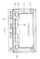
- La figure 1 est une vue schématique en plan d'un boîtier de protection selon l'invention, le couvercle étant supposé enlevé;
- La figure 2 est une vue de côté du boîtier selon la figure 1, la paroi latérale étant supposée enlevée.
- Sur les figures, un automate 10, représenté par son contour externe parallélépipèdique, est logé à l'intérieur d'un boîtier 11 de forme conjuguée. Les dimensions du boîtier 11 sont supérieures à celles de l'automate 10, de façon à ménager sur toutes les faces, un intervalle 12 évitant tout contact mécanique entre l'automate 10 et le boîtier 11. Le boîtier 11 en tôle est obturé d'une manière étanche à sa face supérieure par une plaque métallique 13, fixée par des boulons 14, pour constituer un couvercle donnant accès à l'intérieur d'un boîtier après enlèvement. Le fond opposé 15 peut également être agencé en plaque amovible constituant l'embase de fixation du boîtier. La face avant du boîtier 11 présente un appendice 16 ayant une face inclinée 17 portant des connecteurs 18.
- L'automate 10 est rigidement assujetti par des boulons 20 à un berceau 19, réalisé par des profilés ou des tôles encadrant à faible jeu l'automate 10 sur l'ensemble de ces faces, sauf celle en regard du couvercle 13. Le berceau 19 est prolongé du côté de la face avant par un support 21 de deux ventilateurs 32. Le berceau 19 est lui-même fixé à l'enveloppe du boîtier 11 par des amortisseurs 22 constitués de deux plaques de fixation 23,24, reliées par des tresses élastiques 25. Les amortisseurs 22 peuvent bien entendu être d'un type quelconque, leur disposition et leur nombre étant suffisants pour positionner élastiquement l'ensemble à l'intérieur du boîtier 11 en évitant tout contact mécanique entre l'automate 10 et le boîtier 11, et en amortissant les chocs et les vibrations susceptibles d'être transmis par le boîtier 11 à l'automate 10. L'emploi d'un berceau 19 permet une disposition appropriée des amortisseurs 22, cette disposition étant totalement indépendante des moyens standards de fixation de l'automate 10. L'ensemble automate 10, berceau 19 et ventilateur 32 constitue un ensemble ou bloc susceptible d'être extrait du boîtier 11 après enlèvement du couvercle 13 et déconnexion des amortisseurs 22. Les connecteurs 18 sont reliés par une filerie 26 au bornier (non représenté) de l'automate 10, et cette filerie doit bien entendu également être déconnectée lors d'une séparation de l'automate 10 du boîtier 11. Les connecteurs 18 qui sont des entrées et sorties de l'automate, ainsi que les alimentations de ce dernier sont, si nécessaire, agencées en filtres électriques, bien connus en soi, empêchant toute transmission de parasites vers l'automate 10 ou inversement vers l'extérieur.
- L'automate 10 est séparé du boîtier 11 par l'intervalle d'air 12, et les seules connexions par les amortisseurs 22 et la filerie 26 sont incapables de transmettre à l'automate 10 des chocs ou autres perturbations nuisibles. Le ou les ventilateurs 32 assurent une circulation d'air à l'intérieur du boîtier 11, notamment dans l'intervalle 12 qui assure une uniformisation de la température à l'intérieur du boîtier 11, et une circulation entre l'automate 10, ou plus particulièrement les parties chaudes de l'automate 10, et l'enveloppe métallique du boîtier 11. Cette circulation d'air évite que l'intervalle 12 constitue une isolation thermique empêchant un refroidissement efficace de l'automate 10. Ce refroidissement est réalisé sans solution de continuité de l'étanchéité du boîtier 11, ce qui évite tout risque d'accès de parasites ou de pollution vers l'automate 10. Le degré de protection peut être adapté aux conditions d'utilisation, mais en tous les cas, les moyens de mise en oeuvre sont simples et peu coûteux.
- Il est clair que le ventilateur 32 peut également être fixé à l'enveloppe du boîtier 11, ou que le berceau 19 peut être simplifié et être agencé en simple cadre s'étendant entre les points de fixations des amortisseurs 22 et ceux de l'automate 10. Le boîtier selon l'invention présente l'avantage d'être adaptable à tous type d'appareils électroniques ou automates, et d'être utilisable le cas échéant avec une gamme d'appareils dont les formes ne sont pas obligatoirement parallélépipèdiques.
- L'invention est bien entendu nullement limitée au mode de mise en oeuvre plus particulièrement décrit.
Claims (4)
1. Boîtier de protection d'un appareil électronique en particulier d'un automate (10) de commande d'un processus industriel ou d'un automate à bord d'un navire ou d'un véhicule terrestre, contre les chocs, les parasites extérieures et l'échauffement, comprenant une enveloppe étanche métallique à l'intérieur de laquelle est fixé par des amortisseurs mécaniques (22) ledit automate (10), en ménageant un intervalle (12) d'isolation entre le boîtier (11) et l'automate (10), caractérisé en ce qu'un ventilateur (32), disposé dans le boîtier étanche (11), provoque une circulation de l'air dans ledit intervalle (12) à l'intérieur du boîtier (11) pour uniformiser la température dans ce dernier et améliorer le refroidissement par l'enveloppe métallique externe.
2. Boîtier de protection selon la revendication 1, caractérisé en ce que ladite enveloppe porte des connecteurs (18) des câbles d'entrée et de sortie de l'automate (10), agencés en traversées étanches et en filtres électriques pour assurer avec l'enveloppe métallique la compatibilité électromagnétique.
3. Boîtier de protection selon la revendication 1 ou 2, caractérisé en ce que l'automate (10) est rigidement fixé à un berceau de support (19) qui porte également ledit ventilateur (32) et que lesdits amortisseurs (23) sont montés entre le boîtier (11) et le berceau (19).
4. Boîtier de protection selon la revendication 1,2 ou 3, caractérisé en ce que le boîtier (11) de forme générale parallélépipèdique comporte une face agencée en couvercle (13), dont l'ouverture donne accès aux boulons de fixation du berceau (19) et à la filerie (26) de connexion pour permettre l'extraction de l'automate avec son berceau.
Applications Claiming Priority (2)
| Application Number | Priority Date | Filing Date | Title |
|---|---|---|---|
| FR9014243A FR2668971A1 (fr) | 1990-11-14 | 1990-11-14 | Boitier de protection d'un automate industriel. |
| FR9014243 | 1990-11-14 |
Publications (1)
| Publication Number | Publication Date |
|---|---|
| EP0486406A1 true EP0486406A1 (fr) | 1992-05-20 |
Family
ID=9402239
Family Applications (1)
| Application Number | Title | Priority Date | Filing Date |
|---|---|---|---|
| EP91420395A Withdrawn EP0486406A1 (fr) | 1990-11-14 | 1991-11-06 | Boîtier de protection d'un automate industriel |
Country Status (6)
| Country | Link |
|---|---|
| US (1) | US5202815A (fr) |
| EP (1) | EP0486406A1 (fr) |
| KR (1) | KR920009514A (fr) |
| AU (1) | AU645144B2 (fr) |
| CA (1) | CA2055136A1 (fr) |
| FR (1) | FR2668971A1 (fr) |
Cited By (1)
| Publication number | Priority date | Publication date | Assignee | Title |
|---|---|---|---|---|
| CN111204226A (zh) * | 2018-02-10 | 2020-05-29 | 杭州跟策科技有限公司 | 电动汽车用传感器装置 |
Families Citing this family (13)
| Publication number | Priority date | Publication date | Assignee | Title |
|---|---|---|---|---|
| US5530922A (en) * | 1993-11-09 | 1996-06-25 | Motorola, Inc. | Power detector with matching impedance for radio frequency signal amplifiers |
| US5621363A (en) * | 1994-10-03 | 1997-04-15 | Motorola, Inc. | Modem having an electromagnetic shield for a controller |
| US5808866A (en) * | 1996-09-09 | 1998-09-15 | Gde Systems, Inc. | Ruggedized container system and method |
| JP3147804B2 (ja) * | 1997-02-13 | 2001-03-19 | 住友電装株式会社 | 電子制御ユニットの収容箱 |
| EP0992430A3 (fr) * | 1998-10-07 | 2000-09-13 | Negesat Di Boer Fabrizio & C. SNC | Boítier avec réfrigeration pour équipement à bord d'un véhicule aérien ou spatial |
| TWI222464B (en) * | 1999-02-08 | 2004-10-21 | Kyowa Hakko Kogyo Kk | Process for producing purine nucleotides |
| AT408402B (de) * | 1999-03-23 | 2001-11-26 | Vaillant Gmbh | Transformatorhalterung |
| US6330152B1 (en) * | 2000-06-08 | 2001-12-11 | Lockheed Corp | Apparatus facilitating use of cots electronics in harsh environments |
| US6707675B1 (en) | 2002-12-18 | 2004-03-16 | Hewlett-Packard Development Company, L.P. | EMI containment device and method |
| TWI323283B (en) * | 2004-12-14 | 2010-04-11 | Cj Cheiljedang Corp | 5'-xmp aminase mutant |
| CA2584488A1 (fr) * | 2006-04-06 | 2007-10-06 | Streetlight Intelligence, Inc. | Coffret pour materiel electronique et dispositif d'installation associe |
| FR2968038B1 (fr) * | 2010-11-26 | 2012-12-28 | Snecma | Systeme de detection d'un evenement fugace sur une roue aubagee de moteur d'aeronef |
| DE102011114576A1 (de) * | 2011-09-30 | 2013-04-04 | Thermo Electron (Karlsruhe) Gmbh | Extruder |
Citations (3)
| Publication number | Priority date | Publication date | Assignee | Title |
|---|---|---|---|---|
| FR2284247A1 (fr) * | 1974-09-09 | 1976-04-02 | Siemens Ag | Boitier pour appareils electriques de mesure et/ou de telecommunications |
| WO1987002214A1 (fr) * | 1985-10-03 | 1987-04-09 | Aktiebolaget Bofors | Agencement dans une ou plusieurs unites disposees dans une unite exterieure |
| US4956750A (en) * | 1989-03-17 | 1990-09-11 | Square D Company | Register rack assembly for a programmable controller system |
Family Cites Families (7)
| Publication number | Priority date | Publication date | Assignee | Title |
|---|---|---|---|---|
| DE3135224A1 (de) * | 1981-09-05 | 1983-03-17 | Teldix Gmbh, 6900 Heidelberg | "einrichtung zum halten und lagern von plattenfoermigen teilen" |
| US4688135A (en) * | 1986-08-08 | 1987-08-18 | Eagle Electric Mfg. Co., Inc. | Duplex electrical receptacle with replaceable surge suppressor |
| US5010322A (en) * | 1987-08-12 | 1991-04-23 | Gas Research Institute | Housing for a process controller |
| DE3908532A1 (de) * | 1989-03-16 | 1990-09-20 | Hans Simon | Anschlusssystem fuer entstoerglieder |
| US4926291A (en) * | 1989-07-31 | 1990-05-15 | Western Digital Corporation | Data storage mounting assembly |
| US5034856A (en) * | 1989-10-24 | 1991-07-23 | Hewlett-Packard Company | Modular housing assembly for two incompatible circuits |
| US5030793A (en) * | 1990-05-07 | 1991-07-09 | Motorola Inc. | Integrated EMI filter and thermal heat sink |
-
1990
- 1990-11-14 FR FR9014243A patent/FR2668971A1/fr not_active Withdrawn
-
1991
- 1991-10-30 US US07/784,871 patent/US5202815A/en not_active Expired - Fee Related
- 1991-11-06 EP EP91420395A patent/EP0486406A1/fr not_active Withdrawn
- 1991-11-07 CA CA002055136A patent/CA2055136A1/fr not_active Abandoned
- 1991-11-12 KR KR1019910020062A patent/KR920009514A/ko not_active Withdrawn
- 1991-11-13 AU AU87774/91A patent/AU645144B2/en not_active Expired - Fee Related
Patent Citations (3)
| Publication number | Priority date | Publication date | Assignee | Title |
|---|---|---|---|---|
| FR2284247A1 (fr) * | 1974-09-09 | 1976-04-02 | Siemens Ag | Boitier pour appareils electriques de mesure et/ou de telecommunications |
| WO1987002214A1 (fr) * | 1985-10-03 | 1987-04-09 | Aktiebolaget Bofors | Agencement dans une ou plusieurs unites disposees dans une unite exterieure |
| US4956750A (en) * | 1989-03-17 | 1990-09-11 | Square D Company | Register rack assembly for a programmable controller system |
Cited By (1)
| Publication number | Priority date | Publication date | Assignee | Title |
|---|---|---|---|---|
| CN111204226A (zh) * | 2018-02-10 | 2020-05-29 | 杭州跟策科技有限公司 | 电动汽车用传感器装置 |
Also Published As
| Publication number | Publication date |
|---|---|
| AU8777491A (en) | 1992-05-21 |
| AU645144B2 (en) | 1994-01-06 |
| CA2055136A1 (fr) | 1992-05-15 |
| US5202815A (en) | 1993-04-13 |
| FR2668971A1 (fr) | 1992-05-15 |
| KR920009514A (ko) | 1992-06-25 |
Similar Documents
| Publication | Publication Date | Title |
|---|---|---|
| EP0486406A1 (fr) | Boîtier de protection d'un automate industriel | |
| US10028409B1 (en) | Immersion cooling arrangements | |
| US6156970A (en) | Casing for housing electrical and/or electronic components | |
| FR3079627A1 (fr) | Dispositif optique pour vehicule comprenant un element de chauffage | |
| FR3064878A1 (fr) | Dispositif de dissipation de chaleur d'un dispositif electronique | |
| AU2001264876A1 (en) | Apparatus facilitating use of cots electronics in harsh environments | |
| US20040085733A1 (en) | Heat pipe cooled electronics enclosure | |
| FR2886509A1 (fr) | Dispositif electronique modulaire fonctionnant dans des environnements severes | |
| CN110429765A (zh) | 用于空调设施的电压缩机的马达壳体 | |
| FR2940590A1 (fr) | Pack electrique a modules de commande et de puissance separes. | |
| US12171082B2 (en) | Immersion cooling apparatus | |
| JP2016092046A (ja) | 電気機器用筐体及び電気機器 | |
| CN107851989A (zh) | 防风壳套及包括防风壳套的插接器装置 | |
| KR20160014085A (ko) | 이엠피 방호 캐비닛 | |
| JP2001525989A (ja) | 電子または電気回路のためのハウジング | |
| CN104769826B (zh) | 电连接组件 | |
| KR20150037799A (ko) | 이엠피 방호 캐비닛 | |
| FR3065134B1 (fr) | Haut-parleur et enceinte acoustique le comportant | |
| FR3030999A1 (fr) | Procede et dispositif de refroidissement d'un equipement pourvu de cartes electroniques utilisant au moins une carte distincte de refroidissement par fluide | |
| FR2759845A1 (fr) | Boitier de protection pour circuit electronique | |
| KR101604636B1 (ko) | 가스 버너의 유실열을 이용한 발전 장치 | |
| FR2969775A1 (fr) | Calculateur electronique pour vehicule automobile | |
| FR2676885A1 (fr) | Appareil electronique de commande pour installation dans le compartiment-moteur d'un vehicule automobile. | |
| CN208635179U (zh) | 电暖器 | |
| EP3436296B1 (fr) | Système pour dispositif de chauffage, de ventilation ou de climatisation d'un véhicule |
Legal Events
| Date | Code | Title | Description |
|---|---|---|---|
| PUAI | Public reference made under article 153(3) epc to a published international application that has entered the european phase |
Free format text: ORIGINAL CODE: 0009012 |
|
| AK | Designated contracting states |
Kind code of ref document: A1 Designated state(s): BE CH DE ES GB IT LI SE |
|
| 17P | Request for examination filed |
Effective date: 19921106 |
|
| STAA | Information on the status of an ep patent application or granted ep patent |
Free format text: STATUS: THE APPLICATION IS DEEMED TO BE WITHDRAWN |
|
| 18D | Application deemed to be withdrawn |
Effective date: 19940601 |