EP0486530B1 - Cassette a bande, notamment a bande magnetique, et feuilles intercalaires prevues pour celle-ci - Google Patents
Cassette a bande, notamment a bande magnetique, et feuilles intercalaires prevues pour celle-ci Download PDFInfo
- Publication number
- EP0486530B1 EP0486530B1 EP90911578A EP90911578A EP0486530B1 EP 0486530 B1 EP0486530 B1 EP 0486530B1 EP 90911578 A EP90911578 A EP 90911578A EP 90911578 A EP90911578 A EP 90911578A EP 0486530 B1 EP0486530 B1 EP 0486530B1
- Authority
- EP
- European Patent Office
- Prior art keywords
- longitudinal
- bend
- run
- tape
- cassette
- Prior art date
- Legal status (The legal status is an assumption and is not a legal conclusion. Google has not performed a legal analysis and makes no representation as to the accuracy of the status listed.)
- Expired - Lifetime
Links
- 239000011888 foil Substances 0.000 title description 32
- 238000004804 winding Methods 0.000 claims description 90
- 239000011324 bead Substances 0.000 claims description 18
- 238000004049 embossing Methods 0.000 claims description 16
- 229920000728 polyester Polymers 0.000 claims description 3
- -1 polyethylene terephthalate Polymers 0.000 claims 2
- 229920000139 polyethylene terephthalate Polymers 0.000 claims 2
- 239000005020 polyethylene terephthalate Substances 0.000 claims 2
- 238000009751 slip forming Methods 0.000 claims 1
- 238000005259 measurement Methods 0.000 description 18
- 238000013461 design Methods 0.000 description 5
- 238000004519 manufacturing process Methods 0.000 description 5
- VYZAMTAEIAYCRO-UHFFFAOYSA-N Chromium Chemical compound [Cr] VYZAMTAEIAYCRO-UHFFFAOYSA-N 0.000 description 3
- 230000015572 biosynthetic process Effects 0.000 description 3
- 239000003795 chemical substances by application Substances 0.000 description 3
- 238000010586 diagram Methods 0.000 description 3
- 230000000694 effects Effects 0.000 description 2
- 239000000463 material Substances 0.000 description 2
- 230000000284 resting effect Effects 0.000 description 2
- 238000012549 training Methods 0.000 description 2
- 229920002472 Starch Polymers 0.000 description 1
- 238000005452 bending Methods 0.000 description 1
- 229910052804 chromium Inorganic materials 0.000 description 1
- 239000011651 chromium Substances 0.000 description 1
- 230000000052 comparative effect Effects 0.000 description 1
- 238000009826 distribution Methods 0.000 description 1
- 238000005516 engineering process Methods 0.000 description 1
- 230000002349 favourable effect Effects 0.000 description 1
- 238000003780 insertion Methods 0.000 description 1
- 230000037431 insertion Effects 0.000 description 1
- 238000000034 method Methods 0.000 description 1
- 238000004806 packaging method and process Methods 0.000 description 1
- 229920006267 polyester film Polymers 0.000 description 1
- 239000007787 solid Substances 0.000 description 1
- 239000002904 solvent Substances 0.000 description 1
- 235000019698 starch Nutrition 0.000 description 1
- 239000008107 starch Substances 0.000 description 1
- 239000000725 suspension Substances 0.000 description 1
- 238000012360 testing method Methods 0.000 description 1
Images




Classifications
-
- G—PHYSICS
- G11—INFORMATION STORAGE
- G11B—INFORMATION STORAGE BASED ON RELATIVE MOVEMENT BETWEEN RECORD CARRIER AND TRANSDUCER
- G11B23/00—Record carriers not specific to the method of recording or reproducing; Accessories, e.g. containers, specially adapted for co-operation with the recording or reproducing apparatus ; Intermediate mediums; Apparatus or processes specially adapted for their manufacture
- G11B23/02—Containers; Storing means both adapted to cooperate with the recording or reproducing means
- G11B23/04—Magazines; Cassettes for webs or filaments
- G11B23/08—Magazines; Cassettes for webs or filaments for housing webs or filaments having two distinct ends
- G11B23/087—Magazines; Cassettes for webs or filaments for housing webs or filaments having two distinct ends using two different reels or cores
- G11B23/08707—Details
- G11B23/08757—Guiding means
- G11B23/08764—Liner sheets
Definitions
- the invention relates to a tape cassette, in particular a magnetic tape cassette, with a housing, comprising bottom and cover walls and housing rear and front sides, with at least one tape reel on an essentially flangeless winding core, onto and / or from which a tape is wound up or can be unwound, whereby between the band windings having band windings and the bottom and top walls of the cassette foils with bent or kinked, assigned and opposite each other with respect to the middle layer of the foil are provided, which press resiliently on the band or wraps, the foils in Middle area have longitudinal kinks, which on the one hand partially on the floor or. Support the lid surfaces and have the buckling parts directed towards the tape reel, which at least exert spring pressure forces on the winding core and / or tape reel, as well as suitably designed foils for such tape cassettes.
- a tape cassette in particular a magnetic tape cassette
- a housing comprising bottom and cover walls and housing rear and front sides, with at least one tape reel on an essentially flangeless winding core, onto and / or from which a tape is loaded and unloaded can be unwound
- foils with bent or kinked assigned to one another and opposite one another with respect to the center plane of the cassette are provided, which press resiliently onto the band or wraps, the foils have in the middle area as resilient film areas on both sides of the central longitudinal axis of the cassette arranged longitudinal kinks, which on the one hand are partially supported on the bottom or cover surfaces and on the other hand have kink parts directed towards the tape winding, which at least exert spring pressure forces on the winding core and / or tape winding solved, in that the longitudinal kinks are formed with different cross-sectional shapes to exert differently large spring pressure forces on the at least one winding
- the object is further achieved by a combination of shims for Banbassetten, in particular magnetic tape cassettes, with at least one tape reel on an essentially flangeless winding core, if their two foils are provided with bent or bent, mutually associated and opposite one another with respect to a central plane , wherein the films in their central region as resilient film regions on both sides of the central longitudinal axis of each film have longitudinal creases, which are formed on the one hand on the side of the film facing away from the central plane and on the other hand have creased parts directed towards the central plane with a spring constant, the longitudinal creases being formed with different cross-sectional shapes are used to exert differently large spring pressure forces in the direction of the central plane, and each of the different cross-sectional shapes (DK, EK) either over the entire length of the longitudinal bend (K 1,2; K 3, 4) is provided to generate the respective different spring pressure force over the entire length of each of the longitudinal bends (K 1,2; K 3.4) or the different cross-sectional shapes in the course of at
- Longitudinal buckling is generally understood to mean a region of the film which extends, is bent or kinked in the longitudinal direction of the film (e.g. a film in a compact cassette).
- the longitudinal bends can have different cross-sectional shapes over the course of their longitudinal extension.
- the longitudinal kinks can expediently be arranged inside or just outside the winding core diameter.
- a first longitudinal bend with a relatively large spring pressure force can advantageously be provided on the film between the longitudinal central axis and the rear of the housing, which is designed to be continuous up to the narrow sides of the film .
- a part of a second longitudinal kink which is shorter in comparison with the first longitudinal kink and which is at least in length from one to the other winding core, but not up to the, can be formed in the cassette with the coplanar tape windings between the longitudinal axis of the cassette and the housing front Narrow sides are enough.
- the first longer longitudinal kink and / or the shorter part of the second longitudinal kink are each formed by a double kink, one kink edge for support on the bottom or cover walls and the other kink edge facing the tape wrap.
- first longer longitudinal bend and the shorter part of the second longitudinal bend can each be formed by a relatively narrow bead or embossing with a relatively large spring pressure force.
- the shorter part of the second longitudinal bend is provided at the ends with an inlet / outlet bend part for the tape to be wound up or to be unwound, which continues the second longitudinal bend up to the outline edge of the film and one opposite the shorter one second longitudinal bend has smaller spring pressure. It is thereby achieved that by means of a "softer spring pressure of the buckling part, the incoming and outgoing band section is not changed in its vertical position and formation, for example by inclination or bending, but is still supported and oriented in its vertical position and formation avoided in the film when winding the tape in the cassette production.
- Reaching longitudinal kink with a relatively large spring pressure karft be provided, which is provided at each end with an inlet / outlet kink for the tape to be wound or unwound and which extends to the outline edge of the film.
- This provides a film formation which is completely symmetrical with respect to the central longitudinal axis and which, if it is rectangular as shown in the drawing or is symmetrical with respect to its solvent axis, simplifies film production and the packaging of the films into the cassette.
- the inlet / outlet buckling parts can continue the longitudinal buckling essentially in a straight line up to the ends of the film.
- the inlet / outlet bend parts can also run at an angle to the shorter part of the longitudinal bend, in particular in the direction of a corner of the film.
- the inlet / outlet buckle parts can each be formed by a single buckle with a relatively small spring pressure, the only buckling edge facing the inlet or outlet belt section.
- the inlet / outlet buckle parts can also be formed by a relatively wide bead or embossing with a relatively small spring pressure force, of which the highest elevation in each case faces the incoming or outgoing band section.
- the spring pressure force of the longitudinal kink assigned to the winding core and / or tape roll to the spring pressure force of the longitudinal kink assigned to the entry / exit area of the tape can be in the range from 3: 2 to 4: 1, in particular in the range from 4: 1 to 5: 2 , preferably about 3: 1.
- This provides the option of selecting suitable shims with preselectable spring pressure depending on the thickness and transverse rigidity of the respective cassette tape.
- a film made of polyester, in particular polyterephthalate, with a thickness of 50 ⁇ m can practically have a double crease, the distance between the crease lines in the range of approx. 1.5 to 4 mm, in particular approx. 2 to 3 mm and preferably approx Is 2.4 mm. In this way, favorable spring pressure forces can be realized in the sense of the invention.
- Figure 1 shows a compact cassette K with a housing G, consisting of two rectangular bottom and lid walls la and 1b and side walls 2a, 2b and 2c or 2d, 2e and 2f, which assembled an essentially cuboid cavity 3 for receiving the two winding cores 4a and 4b form the bearing edges 7a and 7b which surround them about axes 5 perpendicular to the main walls 1a, 1b and openings 6a and 6c and 6b and 6d which are coaxial therewith (the associated upper bearing edges are not shown). are rotatably mounted.
- a magnetic tape 8 can be wound between the winding cores 4a and 4b, with it on both The winding cores 4a and 4b are fastened with their ends and the tape winding W located in the drawing on the winding core 4b can be wholly or partially wound onto the winding core 4a and the winding process can then take place in reverse.
- each of the bottom and top walls 1a and 1b is a slide film 9a and 9b such that longitudinal, narrow, parallel, curved or kinked film areas, referred to above as “longitudinal kinks", resiliently against the end faces of the winding cores 4a and 4b, press against the tape winding W and against the magnetic tape 8 itself.
- the longitudinal central axis is designated with MF in all individual film representations.
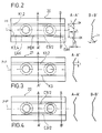
- the rear (first) longitudinal kink K 1,2 with respect to the front 1b of the cassette is continuous up to the film ends and as a double kink, see FIG. e.g. Cross-sectional representation (A-A ', B-B') in Figure 2, formed.
- the front (second) longitudinal bend is labeled C 3/2 because it is a one and a half fold.
- the longitudinal kinks K 1,2 and C 3/2 are designed here as parallel kinks whose distance to the center axis M of the cassette (which corresponds to the longitudinal center axis) is chosen to be constant so that the one with the band 8 and / or the winding cores 4a, 4b and / or the tape rolls W are in longitudinal contact K 1,2 and C 3/2 just outside the outer diameter D of the winding core 4, so that inward bevels are in line contact with the outer upper or lower ring edges of the empty winding core 4, while one after externally directed chamfer faces the incoming winding to be wound up and ensures their alignment and guidance to the winding core.
- the smallest distance d between the longitudinal kinks K 1,2 and C 2/3 in the immediate vicinity of the associated winding core 4 essentially corresponds to the width b of the band 8 or is slightly smaller (d ⁇ b), as indicated in FIG. 8.
- the longitudinal bend C 3/2 from FIG. 2 has a "shorter part" or middle part MDK, which is shorter than the continuous longitudinal bend K 1,2, but otherwise essentially with the same dimensions, but with a shorter length, approximately tangentially from the winding core 4a to 4b is sufficient.
- Extension lines L indicate how two continuous longitudinal kinks K 1, 2 designed as double kinks run, with which embodiment in the measurement diagram in FIG. 10 is to be compared even later.
- the cross section B-B 'of course does not correspond to the DK version, this applies to the cross section A-A'.
- FIG. 10 it can also be seen that the winding cores 4 and tape windings W are pushed to an asymmetry, practically an oblique position with respect to the housing walls 17, and such cassettes tend to increase the torque, although the run-in / run-out characteristics of the tape section are already clear, is improved compared to commercially available cassettes.
- Figure 4 shows double symmetrically arranged C 3/2 longitudinal folds on a film 22, which have advantages in terms of manufacture and any insertion (with respect to the front and back of the cassette!) During assembly.
- FIG. 5 shows the film 23, which is only a slightly larger distance c between the DK C 1, 2 and the combination bend C 3/2, as the distance e in Figure 2, e ⁇ c. This results in reduced guidance, especially of the empty winding core.
- Film 24 in FIG. 6 differs only by two inlet / outlet bends EAK 'which run obliquely to the film outline, but this does not change the function of film 24 compared to film 20.
- the film 25 in FIG. 7 is characterized by delta-shaped inlet / outlet bends (EAK) which, however, are designed as wider double bends or corresponding beads DK '.
- EAK delta-shaped inlet / outlet bends
- MDK central part of the longitudinal bend C 3/2 s can also be designed as a bead or embossing in the latter case.
- Figure 7A shows the central cross-sectional view A-A 'of a pair of foils 25 in the installed position and the reference median plane ME, which represents the median plane of the cassette interior or the medial position of the tape reel in the tape cassette.
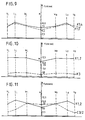
- FIG. 9 shows for the double-kink film from FIG. 1 continuous longitudinal kinks K 1,2 and K 3,4 with the extensions L! The course of the respective spring constant at different locations of the DK film 20 in the cassette K.
- the spring pressure force is measured along the longitudinal bend with the same vertical spring travel of 0.4 mm.
- the indices L and R mean “left” and "right”. It can be seen from FIG. 9 that high spring pressure forces were measured from the outside in, running over the longitudinal direction of the CC.
- Figure 10 shows very different spring pressure forces, the longitudinal kink (EK) K 3 applying only about 1/10 of the spring pressure forces of the longitudinal kink K 1,2 and this can result in an imbalance of the windings.
- FIG. 11 finally shows the result of the C 3/2 longitudinal buckling film 20 (without the extensions L!) Or 25, wherein in the inlet / outlet area (V L , V R ) only about a third of the spring pressure forces compared to those in the longitudinal buckling K 1,2 occurs, so that the tape is wound up and unwound without problems, the winding cores and tape windings are kept in the desired position and electrostatic charges are largely avoided by the small contact surfaces between foils and tape / tape windings.
- ® is a registered trademark of BASF AG, Ludwigshafen
- the height range of the embossments h from 0.28 to 0.53 mm specified in DE-PS 28 25 457 is adjusted by placing film strips in the middle of the cassette (CC A), just like in BASF (CC B), in which the downward and upward-facing, curved or kinked film areas had a total height of 0.8 mm, i.e. had a resilient support on the winding core and tape winding.
- the film thicknesses were the same in both CC's.
- the material was polyterephthalate.
- the winding torque is measured when rewinding a CC, without the magnetic head coming into contact with the tape.
- the winding mandrel is braked with a constant torque of 8 cNcm.
- the winding side has an approximately full winding and the unwinding side has an approximately empty winding.
- the measured values are recorded shortly before the end of the belt run.
- the position of the CC is horizontal during the measurement.
- the speed of the winding mandrel is 500 rpm (revolutions per minute).
- the measuring device is a torque measuring device (self-made by BASF AG, Ludwigshafen) and is based on the measurement of the current increase of the winding motor.
- the wow and flutter measurement is a measurement of the pitch fluctuation of a CC when a recorded measurement signal of the frequency 3150 Hz is reproduced on two different commercially available single capstan recorders, each with 2 magnetic heads.
- the wow and flutter meter from Woelke, 8069 Schweitenmaschinen measures the frequency fluctuations that occur without being evaluated with a demodulator bandwidth of 1000 Hz.
- the ten largest difference values from a large number of measurements are used and by means of an HP 85 B computer (from Hewlett & Packard ), the mean is calculated. All measured values are shown in a frequency distribution and written down over the entire length of the tape.
- Curves A are the measurement curves of the CC UCX-S 90 (Sony) and curves B are those of the BASF CC according to the invention.
- the solid curves show the measured values of the CC unchanged with respect to the tape clip, while the dashed lines show an offset of the tape clip compared to the plane of the winding core of 0.1 mm.
- the CC according to the prior art is therefore not suitable mechanically for all recorders on the market for trouble-free operation and deteriorates the electro-acoustic reproduction by half to two thirds if the tape clip only protrudes by 0.1 mm, which occurs more frequently in terms of production technology.
- the CC A is not suitable for guiding the tape winding and the tape windings to be wound up sufficiently continuously, so that these CC A lead to sticking in approximately 10% of the tested CC number.
- the present invention has achieved the result that there is a continuous spring pressure between the foils and the tape winding or the foils and the tape and this spring pressure should be selected to be different in size over the surface of the foil or the cassette.
- the CC A also has an inclination and a folding over of the incoming / outgoing tape section similar to the film 20 with two double kinks K 1,2 and K 3.4 observed (measured values see FIG. 9), so that in comparison the BASF Chromium Maxima II CC according to the invention with 3 1/2-fold foils performed much better in this respect too (cf. measured values in FIG. 11 and Wow - and Flutter measurements in Figure 12) as the CC A according to the prior art.
- a tape cassette is formed with foils with curved and kinked foil areas, which consist of longitudinal folds, which have different cross-sectional shapes for different spring pressure forces, and which can be used both for guiding the winding core, the tape winding and for aligning and guiding the tape sections to be wound / unwound.
- Practical designs of the longitudinal kinks differ in their various cross-sectional shapes, including those in the course of a longitudinal kink, and in their different arrangements, parallel or at an angle to the longitudinal axis of the cassette.
Landscapes
- Packaging Of Annular Or Rod-Shaped Articles, Wearing Apparel, Cassettes, Or The Like (AREA)
- Decoration Of Textiles (AREA)
- Magnetic Record Carriers (AREA)
- Paints Or Removers (AREA)
- Tape Measures (AREA)
- Impression-Transfer Materials And Handling Thereof (AREA)
Claims (28)
- Cassette à bande, en particulier cassette à bande magnétique, ayant un boîtier, comprenant des parois de fond et de couvercle et des côtés de boîtier arrière et avant, avec au moins un enroulement de bande (W), sur un noyau d'enroulement (4) en principe sans joue, sur lequel et/ou duquel une bande (8) peut être enroulée respectivement déroulée, des feuilles (9, 20 à 25), ayant des zones de feuilles repliées ou infléchies, tournées les unes vers les autres et orientées dans des directions mutuellement opposées par rapport au plan médian de la cassette étant prévues entre l'enroulement de bande (W) présentant les spires de bandes et les parois de fond et de couvercle de la cassette, ces zones de feuilles pressant élastiquement sur le (ou les) enroulement, de bande (W), les feuilles (9, 20 à 25) présentant, dans la zone médiane des inflexions longitudinales (K 1, 2; K 3; C 3/2), disposées, à titre de zones de feuilles élastiques, de part et d'autre de l'axe médian longitudinal (M) de la cassette et prenant appui, d'un côté, partiellement sur les surfaces de fond respectivement de couvercle (17) et présentant, de l'autre côté, des parties d'inflexion orientées vers l'enroulement de bandes (W) , qui exercent des efforts de pression élastique au moins sur le noyau d'enroulement (4) et/ou l'enroulement de bandes (W), caractérisée en ce que les inflexions longitudinales (K 1, 2; K 3; C 3/2) sont réalisées avec des formes de sections transversales différentes, en vue d'exercer des efforts de pression élastique d'ampleur différente sur le (au moins un) noyau d'enroulement (4) et/ou enroulement de bandes (W), chacune des différentes formes de sections transversales (DK; EK) étant prévue, soit sur toute la longueur des inflexions longitudinales (K 1, 2; K 3, 4) pour produire la force de pression élastique spécifique chaque fois différente sur toute la longueur de chacune des inflexions longitudinales (K 1, 2; K 3, 4), ou bien les différentes formes de sections transversales étant prévues au cours d'au moins l'une des inflexions longitudinales (C 3/2) sur chaque fois une partie de sa longueur en vue de produire des efforts de pression élastique différents chaque fois dans des parties de la longueur de la (au moins une) inflexion longitudinale (C 3/2).
- Cassette selon la revendication 1, caractérisée en ce que les inflexions longitudinales (C 3/2) présentent, dans leurs zones médianes (M, D, K) et dans leurs zones d'extrémité (E,A,K), des sections transversales de formes différentes, pour donner des efforts de pression élastique élevés ou faibles.
- Cassette selon la revendication 1, caractérisée en ce que les inflexions longitudinales (K 1, 2; C 3/2) sont disposées à l'intérieur ou juste à l'extérieur du diamètre d'enroulement (D) .
- Cassette selon la revendication 1 et l'une ou les deux des revendications 2 et 3, caractérisée en ce que sont prévus deux noyaux d'enroulements (4a, 4b) pour deux enroulements de bandes (W) situés l'un à côté de l'autre et les centres des noyaux d'enroulements (4) étant reliés ensemble au moyen d'un axe médian longitudinal (M) et en ce que, entre l'axe médian longitudinal (M) et le côté arrière de boîtier (2c, 2f) est prévue une première inflexion longitudinale (K; 1, 2), produisant une force de pression élastique relativement grande et continuant jusqu'aux extrémités de feuilles.
- Cassette selon les revendications 1 et 4, caractérisée en ce que, entre l'axe médian longitudinal de cassette (M) et le côté avant de boîtier (16) est réalisée une deuxième inflexion longitudinale (C 3/2) ayant une partie (MDK) plus courte que la première inflexion longitudinale (K, 1, 2), cette partie (MDK) arrivant au moins jusqu'à l'autre noyau d'enroulement (4a, 4b), mais pas jusqu'aux extrémités de feuille.
- Cassette selon la revendication 4 ou 5, caractérisée en ce que la première inflexion longitudinale (K, 1; 2) et/ou la partie courte (MDK) de la deuxième inflexion longitudinale (C 3/2) sont chacune constituées par une double inflexion (DK), une première arête d'inflexion servant à assurer l'appui sur les parois de fond respectivement de couvercle (17) et l'autre arête d'inflexion étant orientée vers l'enroulement de bande (W).
- Cassette selon la revendication 4 ou 5, caractérisée en ce que la première inflexion longitudinale longue (K; 1, 2) et la partie courte (MDK) de la deuxième inflexion longitudinale (C 3/2) sont chacune constituées par une moulure ou une empreinte relativement étroite (figure 8) avec une force de pression élastique relativement grande.
- Cassette selon la revendication 4, 6 ou 7, caractérisée en ce que la partie courte (MDK) de la deuxième inflexion longitudinale (C 3/2) est pourvue à chacune des extrémités d'une partie d'inflexion d'insertion et de sortie (EAK) pour la bande à enrouler respectivement à dérouler, qui prolonge la partie courte (MDK) de la deuxième inflexion longitudinale (C 3/2) jusqu'à l'arête du contour de la feuille (20, 23 à 25) et présente une force de pression élastique inférieure par rapport à celle que présente la partie courte (MDK) de la deuxième inflexion longitudinale (C 3/2).
- Cassette selon la revendication 1, caractérisée en ce que tant entre l'axe médian longitudinale (M) de la cassette (K) et le côté arrière de boîtier (2c, 2f) qu'également entre l'axe médian longitudinal (M) de la cassette (K) et le côté arrière de boîtier (2c, 2f) qu'également entre l'axe médian longitudinal (M) et le côté avant de boîtier (16) sont prévus chaque fois une partie courte (MDK) , allant jusqu'à l'autre noyau d'enroulement (4a, 4b) d'une inflexion longitudinale (C 3/2) avec une force de pression élastique relativement grande, pourvues à chaque extrémité d'une partie d'inflexion d'entrée respectivement de sortie (EAK) pour la bande (8) à enrouler ou à dérouler et arrivant jusqu'à l'arête du contour de la feuille (22).
- Cassette selon la revendication 8 ou 9, caractérisée en ce que les parties d'inflexion d'entrée/sortie (EAK) prolongent la partie courte (MDK) de l'inflexion longitudinale (C 3/2) sensiblement de façon rectiligne jusqu'aux extrémités de feuille.
- Cassette selon la revendication 8 ou 9, caractérisée en ce que en ce que les parties d'inflexion d'entrée/sortie (EAK) s'étendent avec un angle (δ) par rapport à la partie courte (MDK) de l'inflexion longitudinale (C 3/2), en particulier dans la direction d'un angle de la feuille (24).
- Cassette selon l'une ou plusieurs des revendications 8 à 11, caractérisée en ce que les parties d'inflexion d'entrée/de sortie (EAK) sont dotées d'une force de pression élastique relativement moindre, l'arête d'inflexion unique, la plus haute (EAK) étant tournée vers la section de bande (8) entrant ou sortant.
- Cassette selon l'une des revendications 8 à 11, caractérisée en ce que les parties d'inflexion d'entrée/sortie (EAK) sont constituées chacune par une moulure ou une empreinte relativement large avec une force de pression élastique relativement petite, dont l'élévation la plus forte est tournée vers la section de bande (8) entrant ou sortant.
- Cassette selon l'une des revendications 1 à 13, caractérisée en ce que le rapport entre la force de pression élastique de la première inflexion longitudinale (K 1,2) associée au noyau d'enroulement (4) et/ou à l'enroulement de bande (W) et la force de pression élastique de la deuxième inflexion longitudinale (C 3/2) associée à la zone d'entrée/de sortie de la bande (8), est situé dans la plage allant de 3:2 à 4:1, en particulier dans la plage allant de 4:1 à 5:2, de préférence de 3:1.
- Cassette selon la revendication 6 et l'une ou plusieurs des revendications 1 à 5 et 7 à 14, caractérisée en ce que la feuille (9, 20 à 25) est en polyester, en particulier en terephthalate de polyéthylène, ayant une épaisseur de 50 µm et la distance (1) entre les lignes inflexion de l'inflexion double (DK) est située dans la plage allant d'à peu près 1,5 à 4 mm en particulier dans la plage allant d'à peu près 2 à 3 mm, avec de préférence 1 = 2,4 mm.
- Combinaison de feuilles de garniture, pour cassettes à bande, en particulier cassettes à bande magnétique, avec au moins un enroulement de bande sur un noyau d'enroulement pratiquement sans joue, dont deux feuilles (9, 20 à 25) sont pourvues de zones de feuilles repliées ou infléchies, tournées les unes vers les autres et opposées les unes aux autres par rapport au plan médian (ME), les feuilles (9, 20 à 25) présentant dans leurs zones médianes, servant de zones de feuilles élastiques, de part et d'autre de l'axe longitudinal médian (MF) de chaque feuille des inflexions longitudinales (K 1,2; K 3; C 3/2) qui sont réalisées d'une part du côté de la feuille opposée au plan médian (ME) et qui présente d'autre part des parties d'inflexion, orientées vers le plan médian (ME) ayant une constante élastique, les inflexions longitudinales (K 1,2; L 3,4; C 3/2) étant réalisées avec des formes de sections transversales (DK, EK) différentes pour exercer des efforts de pression élastique de valeurs différentes dans la direction du plan médian (ME) chacune des différentes formes de sections transversales (DK EK) soit sur toute la longueur des inflexions longitudinales (K 1, 2; K 3,4) pour produire la force de pression élastique différente spécifique sur toute la longueur de chacune des inflexions longitudinales (K 1, 2: K 3,4) soit les différentes formes de section transversales étant prévues au cours d'au moins l'une des inflexions longitudinales (C 3/2) sur chaque fois une partie de sa longueur pour produire des efforts de pression élastique différents chaque fois dans des parties de la longueur de la (au moins une) inflexion longitudinale (C 3/2).
- Feuilles selon la revendication 16, caractérisées en ce qu'une première inflexion longitudinale (K 1,2) ayant une constante d'élasticité relativement grande, pour exercer une force de pression élastique relativement grande, est prévue continuant jusqu'aux extrémités de chaque feuille.
- Feuilles selon la revendication 17, caractérisées en ce qu'une deuxième inflexion longitudinale (C 3/2) parallèle et plus courte que la première inflexion longitudinale (K 1,2) est prévue et est disposée symétriquement par rapport à l'axe médian transversale (A-A′) de la feuille.
- Feuilles selon la revendication 18, caractérisées en ce que la première inflexion longitudinale longue (K 1,2) et/ou la partie courte (MDK) de la deuxième inflexion longitudinale (C 3/2) sont chacune formées par une double inflexion (DK), la première arête d'inflexion étant orientée vers le plan médian (ME) et l'autre arête d'inflexion étant orientée vers le côté de chaque feuille opposé au plan médian (ME).
- Feuilles selon la revendication 19, caractérisées en ce que la première inflexion longitudinale longue (K 1,2) et la partie courte (MDK) de la deuxième inflexion longitudinale (C 3/2) sont chacune formées par au moins une moulure ou une empreinte relativement étroite (figure 8) avec une force de pression élastique relativement grande.
- Feuilles selon les revendications 18, 19 ou 20, caractérisées en ce que la partie courte (MDK) de la deuxième inflexion longitudinale (C 3/2) est pourvue, à chacune des extrémités, d'une partie d'inflexion d'entrée/sortie (EAK) pour la bande (8) à enrouler ou à dérouler, qui prolonge la partie courte (MDK) de la deuxième inflexion longitudinale (C 3/2) jusqu'à l'arête du contour de la feuille (20, 23 à 25) et présente une force de pression élastique inférieure par rapport à celle que présente la partie courte (MDK) de la deuxième inflexion longitudinale (C 3/2).
- Feuilles selon la revendication 16, caractérisées en ce que, symétriquement par rapport à l'axe médian longitudinale (MF) des feuilles, est prévu chaque fois une partie courte (MDK), située à l'intérieur par rapport à l'axe médian longitudinal, d'une inflexion longitudinale (C 3/2), ayant une force de pression élastique relativement grande, pourvue à chaque extrémité d'une partie d'inflexion d'entrée/sortie (EAK) située à l'extérieur par rapport à l'axe médian longitudinal (MF) pour la bande (8) à enrouler respectivement à dérouler et arrivant jusqu'à l'arête de contour de la feuille (22).
- Feuilles selon la revendication 21 ou 22, caractérisées en ce que les parties d'inflexion d'entrée/sortie (EAK) prolongent la partie courte (MDK) de l'inflexion longitudinale (C 3/2) sensiblement de façon rectiligne jusqu'aux extrémités de feuille.
- Feuilles selon la revendication 21 ou 22, caractérisées en ce que les parties d'inflexion d'entrée/sortie (EAK) s'étendent avec un angle (δ) par rapport à la partie courte (MDK) de l'inflexion longitudinale (C 3/2), en particulier dans la direction d'un angle de la feuille (24).
- Feuilles selon l'une ou plusieurs des revendications 21 à 24, caractérisées en ce que les parties d'inflexion d'entrée/de sortie (EAK) sont dotées d'une force de pression élastique relativement moindre, l'arête d'inflexion unique la plus haute (EAK) étant tournée vers la section de bande (8) entrant ou sortant.
- Feuilles selon l'une ou plusieurs des revendications 21 à 24, caractérisées en ce que les parties d'inflexion d'entrée/sortie (EAK) sont constituées chacune par une moulure ou une empreinte relativement large avec une force de pression élastique relativement petite, dont l'élévation chaque fois la plus forte est tournée vers la section de bande (8) entrant ou sortant.
- Feuilles selon l'une ou plusieurs des revendications 16 à 26, caractérisées en ce que la force de pression élastique de la première inflexion longitudinale (K 1,2) associée au noyau d'enroulement (4) et/ou à l'enroulement de bande (W) est située, par rapport à la force de pression élastique de la deuxième inflexion longitudinale (C 3/2) associée à la zone d'entrée/de sortie de la bande (8), en un rapport situé dans la plage allant de 3:2 à 4:1, en particulier dans la plage allant de 4:1 à 5:2, en se situant de préférence à 3:1.
- Feuilles selon la revendication 17 et l'une ou plusieurs des revendications 17 à 27, caractérisées en ce que la feuille (9, 20 à 25) est en polyester, en particulier en terephthalate de polyéthylène, ayant une épaisseur de 50 µm et la distance (l) entre les lignes d'inflexion de l'inflexion double (DK) est située dans la plage allant d'à peu près 1,5 à 4 mm en particulier dans la plage allant d'à peu près 2 à 3 mm, avec de préférence 1 = 2,4 mm.
Applications Claiming Priority (3)
| Application Number | Priority Date | Filing Date | Title |
|---|---|---|---|
| DE8909704U DE8909704U1 (de) | 1989-08-12 | 1989-08-12 | Bandkassette, insbesondere Magnetbandkassette |
| DE8909704U | 1989-08-12 | ||
| PCT/EP1990/001316 WO1991003051A1 (fr) | 1989-08-12 | 1990-08-10 | Cassette a bande, notamment a bande magnetique, et feuilles intercalaires prevues pour celle-ci |
Publications (2)
| Publication Number | Publication Date |
|---|---|
| EP0486530A1 EP0486530A1 (fr) | 1992-05-27 |
| EP0486530B1 true EP0486530B1 (fr) | 1994-10-19 |
Family
ID=6841932
Family Applications (1)
| Application Number | Title | Priority Date | Filing Date |
|---|---|---|---|
| EP90911578A Expired - Lifetime EP0486530B1 (fr) | 1989-08-12 | 1990-08-10 | Cassette a bande, notamment a bande magnetique, et feuilles intercalaires prevues pour celle-ci |
Country Status (11)
| Country | Link |
|---|---|
| US (1) | US5402296A (fr) |
| EP (1) | EP0486530B1 (fr) |
| JP (1) | JP2888975B2 (fr) |
| CN (1) | CN1033295C (fr) |
| AT (1) | ATE113136T1 (fr) |
| AU (1) | AU651796B2 (fr) |
| DE (3) | DE8909704U1 (fr) |
| DK (1) | DK0486530T3 (fr) |
| ES (1) | ES2063371T3 (fr) |
| WO (1) | WO1991003051A1 (fr) |
| ZA (1) | ZA906376B (fr) |
Families Citing this family (5)
| Publication number | Priority date | Publication date | Assignee | Title |
|---|---|---|---|---|
| DE8909704U1 (de) * | 1989-08-12 | 1989-11-23 | Basf Ag, 6700 Ludwigshafen | Bandkassette, insbesondere Magnetbandkassette |
| EP0646919B1 (fr) * | 1990-02-22 | 2000-05-03 | Fuji Photo Film Co., Ltd. | Cassette à bande magnétique |
| JPH05347080A (ja) * | 1992-04-15 | 1993-12-27 | Matsushita Electric Ind Co Ltd | テープカセット |
| US5558292A (en) * | 1993-12-24 | 1996-09-24 | U.S. Philips Corporation | Magnetic-tape cassette having at least one antifriction foil separated from an antifriction-foil stack |
| JP2008186492A (ja) * | 2007-01-26 | 2008-08-14 | Tdk Corp | 情報媒体 |
Citations (1)
| Publication number | Priority date | Publication date | Assignee | Title |
|---|---|---|---|---|
| DE2825457A1 (de) * | 1977-06-10 | 1979-01-04 | Sony Corp | Bandkassette |
Family Cites Families (13)
| Publication number | Priority date | Publication date | Assignee | Title |
|---|---|---|---|---|
| DE2251746C3 (de) * | 1972-10-21 | 1982-05-19 | Basf Ag, 6700 Ludwigshafen | Magnetbandkassette, insbesondere Kompaktkassette |
| JPS5073618A (fr) * | 1973-08-17 | 1975-06-17 | ||
| JPS5914948Y2 (ja) * | 1979-03-19 | 1984-05-02 | ティーディーケイ株式会社 | カセツト |
| JPS5839787U (ja) * | 1981-09-09 | 1983-03-15 | オリンパス光学工業株式会社 | カセツトのライナ−シ−ト |
| DE8401561U1 (de) * | 1984-01-20 | 1984-05-03 | Basf Ag, 6700 Ludwigshafen | Bandkassette, insbesondere magnetbandkassette und beilagefolie dafuer |
| DE8415333U1 (de) * | 1984-05-19 | 1984-11-22 | Basf Ag, 6700 Ludwigshafen | Magnetbandkassette, insbesondere kompaktkassette |
| NL8500888A (nl) * | 1985-03-27 | 1986-10-16 | Polygram Bv | Magneetbandcassette, alsmede wikkelinrichting toepasbaar in combinatie met een dergelijke cassette. |
| DE8509882U1 (de) * | 1985-04-02 | 1985-07-25 | Basf Ag, 6700 Ludwigshafen | Bandkassette, insbesondere Magnetbandkassette |
| IT210557Z2 (it) * | 1986-12-04 | 1988-12-30 | Atb Spa | Struttra di mascherina per cassette di nastro magnetico con mezzi di bloccaggio rispetto all'involucro scatolare. |
| IT1199703B (it) * | 1986-12-04 | 1988-12-30 | Atb Spa | Mascherina per cassette di nastro magnetico |
| GB2211818B (en) * | 1987-10-31 | 1992-03-18 | Taiyo Yuden Kk | Magnetic tape cassette |
| SU1693636A1 (ru) * | 1989-07-26 | 1991-11-23 | Научно-Исследовательский Институт Электромеханических Приборов Киевского Научно-Производственного Объединения "Маяк" | Кассета дл магнитной ленты |
| DE8909704U1 (de) * | 1989-08-12 | 1989-11-23 | Basf Ag, 6700 Ludwigshafen | Bandkassette, insbesondere Magnetbandkassette |
-
1989
- 1989-08-12 DE DE8909704U patent/DE8909704U1/de not_active Expired - Lifetime
-
1990
- 1990-07-21 DE DE9010867U patent/DE9010867U1/de not_active Expired - Lifetime
- 1990-08-10 AT AT90911578T patent/ATE113136T1/de not_active IP Right Cessation
- 1990-08-10 US US08/154,707 patent/US5402296A/en not_active Expired - Fee Related
- 1990-08-10 EP EP90911578A patent/EP0486530B1/fr not_active Expired - Lifetime
- 1990-08-10 DE DE59007519T patent/DE59007519D1/de not_active Expired - Fee Related
- 1990-08-10 AU AU61543/90A patent/AU651796B2/en not_active Expired - Fee Related
- 1990-08-10 WO PCT/EP1990/001316 patent/WO1991003051A1/fr not_active Ceased
- 1990-08-10 DK DK90911578.4T patent/DK0486530T3/da active
- 1990-08-10 JP JP2511202A patent/JP2888975B2/ja not_active Expired - Fee Related
- 1990-08-10 ES ES90911578T patent/ES2063371T3/es not_active Expired - Lifetime
- 1990-08-11 CN CN90107124A patent/CN1033295C/zh not_active Expired - Fee Related
- 1990-08-13 ZA ZA906376A patent/ZA906376B/xx unknown
Patent Citations (1)
| Publication number | Priority date | Publication date | Assignee | Title |
|---|---|---|---|---|
| DE2825457A1 (de) * | 1977-06-10 | 1979-01-04 | Sony Corp | Bandkassette |
Also Published As
| Publication number | Publication date |
|---|---|
| AU6154390A (en) | 1991-04-03 |
| JPH05501470A (ja) | 1993-03-18 |
| DK0486530T3 (da) | 1994-11-14 |
| DE8909704U1 (de) | 1989-11-23 |
| ZA906376B (en) | 1992-04-29 |
| US5402296A (en) | 1995-03-28 |
| EP0486530A1 (fr) | 1992-05-27 |
| DE59007519D1 (de) | 1994-11-24 |
| AU651796B2 (en) | 1994-08-04 |
| DE9010867U1 (de) | 1990-10-25 |
| ES2063371T3 (es) | 1995-01-01 |
| CN1033295C (zh) | 1996-11-13 |
| ATE113136T1 (de) | 1994-11-15 |
| WO1991003051A1 (fr) | 1991-03-07 |
| JP2888975B2 (ja) | 1999-05-10 |
| CN1049567A (zh) | 1991-02-27 |
Similar Documents
| Publication | Publication Date | Title |
|---|---|---|
| DE2230281C3 (fr) | ||
| DE2707804C2 (de) | Magnetbandkassette | |
| DE2150806A1 (de) | Auskleidungsfolie fuer Magnetbandkassetten | |
| EP0486530B1 (fr) | Cassette a bande, notamment a bande magnetique, et feuilles intercalaires prevues pour celle-ci | |
| EP0486614B1 (fr) | Cassette a bande, notamment a bande magnetique | |
| DE2617425A1 (de) | Wickelkern fuer bahnmaterial | |
| DE2647691A1 (de) | Magnetbandkassette | |
| DE3010405C2 (fr) | ||
| DE3780150T2 (de) | Gleitblatt fuer magnetbandkassetten. | |
| DE69116394T2 (de) | Magnetbandkassette | |
| DE2501914C3 (de) | Magnetbandkassette | |
| EP0203302B1 (fr) | Cassette à bande, notamment cassette à bande magnétique avec feuille de guidage | |
| CH646266A5 (de) | Magnetbandkassette. | |
| DE3151742A1 (de) | Kassettenbandgeraet | |
| DE4447031C2 (de) | Wickeleinrichtung für bandförmige Aufzeichnungsträger | |
| DE4204134C2 (de) | Vorrichtung zum Aufbringen einer mechanischen Spannung auf ein in eine Kassette eingelegtes Band | |
| DE2642439A1 (de) | Magnetbandkassette | |
| DE3023142C2 (de) | Vorrichtung zum automatischen Anwickeln metallisierter und/oder nichtmetallisierter Bänder auf Kernrohre großen Durchmessers | |
| DE2536385B2 (de) | Magnetbandkassette | |
| DE3302645C2 (de) | Endlosbandvorrichtung | |
| DE3110998C2 (de) | Endlosmagnetbandkassette für hohe Bandgeschwindigkeiten | |
| DE1286306B (de) | Tonbandkassette | |
| DE2347620B2 (de) | Bandführungsvorrichtung für ein Endlosband | |
| CH672557A5 (en) | Magnetic tape cassette with lateral tape guidance rollers - extends region of guidance of edges of tape beyond usual range bounded by forward leading rollers | |
| DE7403422U (de) | Aufnahme- und/oder Antriebsanordnung für eine Spule |
Legal Events
| Date | Code | Title | Description |
|---|---|---|---|
| PUAI | Public reference made under article 153(3) epc to a published international application that has entered the european phase |
Free format text: ORIGINAL CODE: 0009012 |
|
| 17P | Request for examination filed |
Effective date: 19911220 |
|
| AK | Designated contracting states |
Kind code of ref document: A1 Designated state(s): AT BE CH DE DK ES FR GB IT LI LU NL SE |
|
| 17Q | First examination report despatched |
Effective date: 19940110 |
|
| GRAA | (expected) grant |
Free format text: ORIGINAL CODE: 0009210 |
|
| AK | Designated contracting states |
Kind code of ref document: B1 Designated state(s): AT BE CH DE DK ES FR GB IT LI LU NL SE |
|
| REF | Corresponds to: |
Ref document number: 113136 Country of ref document: AT Date of ref document: 19941115 Kind code of ref document: T |
|
| REG | Reference to a national code |
Ref country code: DK Ref legal event code: T3 |
|
| REF | Corresponds to: |
Ref document number: 59007519 Country of ref document: DE Date of ref document: 19941124 |
|
| ITF | It: translation for a ep patent filed | ||
| GBT | Gb: translation of ep patent filed (gb section 77(6)(a)/1977) |
Effective date: 19941103 |
|
| REG | Reference to a national code |
Ref country code: ES Ref legal event code: FG2A Ref document number: 2063371 Country of ref document: ES Kind code of ref document: T3 |
|
| EAL | Se: european patent in force in sweden |
Ref document number: 90911578.4 |
|
| ET | Fr: translation filed | ||
| PLBE | No opposition filed within time limit |
Free format text: ORIGINAL CODE: 0009261 |
|
| STAA | Information on the status of an ep patent application or granted ep patent |
Free format text: STATUS: NO OPPOSITION FILED WITHIN TIME LIMIT |
|
| 26N | No opposition filed | ||
| NLS | Nl: assignments of ep-patents |
Owner name: EMTEC MAGNETICS GMBH |
|
| REG | Reference to a national code |
Ref country code: ES Ref legal event code: PC2A |
|
| REG | Reference to a national code |
Ref country code: CH Ref legal event code: PUE Owner name: BASF AKTIENGESELLSCHAFT TRANSFER- EMTEC MAGNETICS Ref country code: CH Ref legal event code: NV Representative=s name: SCHMAUDER & PARTNER AG PATENTANWALTSBUERO |
|
| REG | Reference to a national code |
Ref country code: GB Ref legal event code: IF02 |
|
| PGFP | Annual fee paid to national office [announced via postgrant information from national office to epo] |
Ref country code: GB Payment date: 20020724 Year of fee payment: 13 |
|
| PGFP | Annual fee paid to national office [announced via postgrant information from national office to epo] |
Ref country code: LU Payment date: 20020725 Year of fee payment: 13 |
|
| PGFP | Annual fee paid to national office [announced via postgrant information from national office to epo] |
Ref country code: SE Payment date: 20020726 Year of fee payment: 13 Ref country code: NL Payment date: 20020726 Year of fee payment: 13 Ref country code: DK Payment date: 20020726 Year of fee payment: 13 Ref country code: CH Payment date: 20020726 Year of fee payment: 13 |
|
| PGFP | Annual fee paid to national office [announced via postgrant information from national office to epo] |
Ref country code: FR Payment date: 20020729 Year of fee payment: 13 Ref country code: AT Payment date: 20020729 Year of fee payment: 13 |
|
| PGFP | Annual fee paid to national office [announced via postgrant information from national office to epo] |
Ref country code: DE Payment date: 20020730 Year of fee payment: 13 |
|
| PGFP | Annual fee paid to national office [announced via postgrant information from national office to epo] |
Ref country code: BE Payment date: 20020808 Year of fee payment: 13 |
|
| PGFP | Annual fee paid to national office [announced via postgrant information from national office to epo] |
Ref country code: ES Payment date: 20020809 Year of fee payment: 13 |
|
| PG25 | Lapsed in a contracting state [announced via postgrant information from national office to epo] |
Ref country code: LU Free format text: LAPSE BECAUSE OF NON-PAYMENT OF DUE FEES Effective date: 20030810 Ref country code: GB Free format text: LAPSE BECAUSE OF NON-PAYMENT OF DUE FEES Effective date: 20030810 Ref country code: AT Free format text: LAPSE BECAUSE OF NON-PAYMENT OF DUE FEES Effective date: 20030810 |
|
| PG25 | Lapsed in a contracting state [announced via postgrant information from national office to epo] |
Ref country code: SE Free format text: LAPSE BECAUSE OF NON-PAYMENT OF DUE FEES Effective date: 20030811 Ref country code: ES Free format text: LAPSE BECAUSE OF NON-PAYMENT OF DUE FEES Effective date: 20030811 |
|
| PG25 | Lapsed in a contracting state [announced via postgrant information from national office to epo] |
Ref country code: LI Free format text: LAPSE BECAUSE OF NON-PAYMENT OF DUE FEES Effective date: 20030831 Ref country code: CH Free format text: LAPSE BECAUSE OF NON-PAYMENT OF DUE FEES Effective date: 20030831 Ref country code: BE Free format text: LAPSE BECAUSE OF NON-PAYMENT OF DUE FEES Effective date: 20030831 |
|
| PG25 | Lapsed in a contracting state [announced via postgrant information from national office to epo] |
Ref country code: DK Free format text: LAPSE BECAUSE OF NON-PAYMENT OF DUE FEES Effective date: 20030901 |
|
| BERE | Be: lapsed |
Owner name: *EMTEC MAGNRTICS G.M.B.H. Effective date: 20030831 |
|
| PG25 | Lapsed in a contracting state [announced via postgrant information from national office to epo] |
Ref country code: NL Free format text: LAPSE BECAUSE OF NON-PAYMENT OF DUE FEES Effective date: 20040301 |
|
| PG25 | Lapsed in a contracting state [announced via postgrant information from national office to epo] |
Ref country code: DE Free format text: LAPSE BECAUSE OF NON-PAYMENT OF DUE FEES Effective date: 20040302 |
|
| REG | Reference to a national code |
Ref country code: DK Ref legal event code: EBP |
|
| EUG | Se: european patent has lapsed | ||
| GBPC | Gb: european patent ceased through non-payment of renewal fee |
Effective date: 20030810 |
|
| REG | Reference to a national code |
Ref country code: CH Ref legal event code: PL |
|
| PG25 | Lapsed in a contracting state [announced via postgrant information from national office to epo] |
Ref country code: FR Free format text: LAPSE BECAUSE OF NON-PAYMENT OF DUE FEES Effective date: 20040430 |
|
| NLV4 | Nl: lapsed or anulled due to non-payment of the annual fee |
Effective date: 20040301 |
|
| REG | Reference to a national code |
Ref country code: FR Ref legal event code: ST |
|
| REG | Reference to a national code |
Ref country code: ES Ref legal event code: FD2A Effective date: 20030811 |
|
| PG25 | Lapsed in a contracting state [announced via postgrant information from national office to epo] |
Ref country code: IT Free format text: LAPSE BECAUSE OF NON-PAYMENT OF DUE FEES;WARNING: LAPSES OF ITALIAN PATENTS WITH EFFECTIVE DATE BEFORE 2007 MAY HAVE OCCURRED AT ANY TIME BEFORE 2007. THE CORRECT EFFECTIVE DATE MAY BE DIFFERENT FROM THE ONE RECORDED. Effective date: 20050810 |