EP0486597B1 - Polyimidwellenleiter als optische sensoren - Google Patents
Polyimidwellenleiter als optische sensoren Download PDFInfo
- Publication number
- EP0486597B1 EP0486597B1 EP90912918A EP90912918A EP0486597B1 EP 0486597 B1 EP0486597 B1 EP 0486597B1 EP 90912918 A EP90912918 A EP 90912918A EP 90912918 A EP90912918 A EP 90912918A EP 0486597 B1 EP0486597 B1 EP 0486597B1
- Authority
- EP
- European Patent Office
- Prior art keywords
- polyimide
- waveguide
- hfda
- hfdam
- polarized light
- Prior art date
- Legal status (The legal status is an assumption and is not a legal conclusion. Google has not performed a legal analysis and makes no representation as to the accuracy of the status listed.)
- Expired - Lifetime
Links
- 229920001721 polyimide Polymers 0.000 title claims abstract description 75
- 239000004642 Polyimide Substances 0.000 title claims abstract description 67
- 230000003287 optical effect Effects 0.000 title claims abstract description 23
- 239000007788 liquid Substances 0.000 claims abstract description 21
- 239000012808 vapor phase Substances 0.000 claims abstract description 21
- 239000000758 substrate Substances 0.000 claims abstract description 14
- 239000004962 Polyamide-imide Substances 0.000 claims abstract description 9
- 229920002312 polyamide-imide Polymers 0.000 claims abstract description 9
- VHUUQVKOLVNVRT-UHFFFAOYSA-N Ammonium hydroxide Chemical compound [NH4+].[OH-] VHUUQVKOLVNVRT-UHFFFAOYSA-N 0.000 claims abstract description 5
- 235000011114 ammonium hydroxide Nutrition 0.000 claims abstract description 5
- 230000010287 polarization Effects 0.000 claims description 23
- XLYOFNOQVPJJNP-UHFFFAOYSA-N water Substances O XLYOFNOQVPJJNP-UHFFFAOYSA-N 0.000 claims description 16
- 238000005259 measurement Methods 0.000 claims description 14
- 239000011521 glass Substances 0.000 claims description 6
- PAYRUJLWNCNPSJ-UHFFFAOYSA-N Aniline Chemical compound NC1=CC=CC=C1 PAYRUJLWNCNPSJ-UHFFFAOYSA-N 0.000 claims description 4
- 230000005684 electric field Effects 0.000 claims description 4
- 150000001735 carboxylic acids Chemical class 0.000 claims description 2
- 239000000295 fuel oil Substances 0.000 claims description 2
- 238000010438 heat treatment Methods 0.000 claims description 2
- 230000010363 phase shift Effects 0.000 claims description 2
- 230000008878 coupling Effects 0.000 claims 2
- 238000010168 coupling process Methods 0.000 claims 2
- 238000005859 coupling reaction Methods 0.000 claims 2
- -1 C1-C3-alcohols Substances 0.000 claims 1
- 230000000694 effects Effects 0.000 claims 1
- 239000010410 layer Substances 0.000 description 47
- 230000004075 alteration Effects 0.000 description 19
- OKKJLVBELUTLKV-UHFFFAOYSA-N Methanol Chemical compound OC OKKJLVBELUTLKV-UHFFFAOYSA-N 0.000 description 18
- 239000012071 phase Substances 0.000 description 16
- 230000035945 sensitivity Effects 0.000 description 13
- 238000000034 method Methods 0.000 description 10
- 230000003993 interaction Effects 0.000 description 9
- 238000011088 calibration curve Methods 0.000 description 8
- 238000001514 detection method Methods 0.000 description 8
- 239000000203 mixture Substances 0.000 description 7
- LFQSCWFLJHTTHZ-UHFFFAOYSA-N Ethanol Chemical compound CCO LFQSCWFLJHTTHZ-UHFFFAOYSA-N 0.000 description 6
- 235000019441 ethanol Nutrition 0.000 description 6
- 238000010521 absorption reaction Methods 0.000 description 5
- 239000000463 material Substances 0.000 description 5
- 230000008569 process Effects 0.000 description 5
- 238000003795 desorption Methods 0.000 description 3
- 210000004209 hair Anatomy 0.000 description 3
- 150000001298 alcohols Chemical class 0.000 description 2
- 230000008859 change Effects 0.000 description 2
- 238000006243 chemical reaction Methods 0.000 description 2
- 238000009792 diffusion process Methods 0.000 description 2
- 239000000835 fiber Substances 0.000 description 2
- 239000005308 flint glass Substances 0.000 description 2
- 229920002647 polyamide Polymers 0.000 description 2
- 230000005855 radiation Effects 0.000 description 2
- 239000000126 substance Substances 0.000 description 2
- 239000004753 textile Substances 0.000 description 2
- HLBLWEWZXPIGSM-UHFFFAOYSA-N 4-Aminophenyl ether Chemical compound C1=CC(N)=CC=C1OC1=CC=C(N)C=C1 HLBLWEWZXPIGSM-UHFFFAOYSA-N 0.000 description 1
- LGRFSURHDFAFJT-UHFFFAOYSA-N Phthalic anhydride Natural products C1=CC=C2C(=O)OC(=O)C2=C1 LGRFSURHDFAFJT-UHFFFAOYSA-N 0.000 description 1
- 239000004952 Polyamide Substances 0.000 description 1
- VYPSYNLAJGMNEJ-UHFFFAOYSA-N Silicium dioxide Chemical compound O=[Si]=O VYPSYNLAJGMNEJ-UHFFFAOYSA-N 0.000 description 1
- 238000000576 coating method Methods 0.000 description 1
- 230000000052 comparative effect Effects 0.000 description 1
- 230000001419 dependent effect Effects 0.000 description 1
- 230000006870 function Effects 0.000 description 1
- 125000005462 imide group Chemical group 0.000 description 1
- 238000004519 manufacturing process Methods 0.000 description 1
- 230000005693 optoelectronics Effects 0.000 description 1
- 229920002120 photoresistant polymer Polymers 0.000 description 1
- 230000000704 physical effect Effects 0.000 description 1
- 229920006254 polymer film Polymers 0.000 description 1
- BDERNNFJNOPAEC-UHFFFAOYSA-N propan-1-ol Chemical compound CCCO BDERNNFJNOPAEC-UHFFFAOYSA-N 0.000 description 1
- 239000000741 silica gel Substances 0.000 description 1
- 229910002027 silica gel Inorganic materials 0.000 description 1
- 239000002356 single layer Substances 0.000 description 1
- 238000001228 spectrum Methods 0.000 description 1
- 238000009423 ventilation Methods 0.000 description 1
Images


Classifications
-
- G—PHYSICS
- G02—OPTICS
- G02B—OPTICAL ELEMENTS, SYSTEMS OR APPARATUS
- G02B6/00—Light guides; Structural details of arrangements comprising light guides and other optical elements, e.g. couplings
- G02B6/10—Light guides; Structural details of arrangements comprising light guides and other optical elements, e.g. couplings of the optical waveguide type
-
- G—PHYSICS
- G01—MEASURING; TESTING
- G01N—INVESTIGATING OR ANALYSING MATERIALS BY DETERMINING THEIR CHEMICAL OR PHYSICAL PROPERTIES
- G01N21/00—Investigating or analysing materials by the use of optical means, i.e. using sub-millimetre waves, infrared, visible or ultraviolet light
- G01N21/75—Systems in which material is subjected to a chemical reaction, the progress or the result of the reaction being investigated
- G01N21/77—Systems in which material is subjected to a chemical reaction, the progress or the result of the reaction being investigated by observing the effect on a chemical indicator
- G01N21/7703—Systems in which material is subjected to a chemical reaction, the progress or the result of the reaction being investigated by observing the effect on a chemical indicator using reagent-clad optical fibres or optical waveguides
-
- G—PHYSICS
- G01—MEASURING; TESTING
- G01N—INVESTIGATING OR ANALYSING MATERIALS BY DETERMINING THEIR CHEMICAL OR PHYSICAL PROPERTIES
- G01N21/00—Investigating or analysing materials by the use of optical means, i.e. using sub-millimetre waves, infrared, visible or ultraviolet light
- G01N21/17—Systems in which incident light is modified in accordance with the properties of the material investigated
- G01N21/21—Polarisation-affecting properties
- G01N21/23—Bi-refringence
-
- G—PHYSICS
- G01—MEASURING; TESTING
- G01N—INVESTIGATING OR ANALYSING MATERIALS BY DETERMINING THEIR CHEMICAL OR PHYSICAL PROPERTIES
- G01N21/00—Investigating or analysing materials by the use of optical means, i.e. using sub-millimetre waves, infrared, visible or ultraviolet light
- G01N21/17—Systems in which incident light is modified in accordance with the properties of the material investigated
- G01N21/41—Refractivity; Phase-affecting properties, e.g. optical path length
- G01N21/43—Refractivity; Phase-affecting properties, e.g. optical path length by measuring critical angle
- G01N21/431—Dip refractometers, e.g. using optical fibres
-
- G—PHYSICS
- G02—OPTICS
- G02B—OPTICAL ELEMENTS, SYSTEMS OR APPARATUS
- G02B6/00—Light guides; Structural details of arrangements comprising light guides and other optical elements, e.g. couplings
- G02B6/10—Light guides; Structural details of arrangements comprising light guides and other optical elements, e.g. couplings of the optical waveguide type
- G02B6/12—Light guides; Structural details of arrangements comprising light guides and other optical elements, e.g. couplings of the optical waveguide type of the integrated circuit kind
- G02B6/13—Integrated optical circuits characterised by the manufacturing method
- G02B6/136—Integrated optical circuits characterised by the manufacturing method by etching
-
- G—PHYSICS
- G01—MEASURING; TESTING
- G01N—INVESTIGATING OR ANALYSING MATERIALS BY DETERMINING THEIR CHEMICAL OR PHYSICAL PROPERTIES
- G01N21/00—Investigating or analysing materials by the use of optical means, i.e. using sub-millimetre waves, infrared, visible or ultraviolet light
- G01N21/17—Systems in which incident light is modified in accordance with the properties of the material investigated
- G01N21/21—Polarisation-affecting properties
Definitions
- the invention relates to a polyimide waveguide as an optical sensor which is used for the quantitative detection of liquids in the vapor phase, particularly, polar liquids in the vapor phase and for the detection of NH3, "NH4OH", NO2 and N2O5.
- Polyimides are used as material for waveguides and in optoelectronics as coatings and fillings for electronic embedding material. This utility of polyimides arises from their sensitivity to "humidity" due to interactions of the vapor phase of the liquid components in the vicinity of the surface of the polyimide. Humidity measurements are usually obtained by two methods. For example, in the hair hygrometer method, the dependence of the lenght of a hair or textile fiber upon humidity is determined by means of specially prepared hairs and textile fibers, inter alia. Another method, the capacitive process utilizes a polymer film wherein the "humidity" is measured by an altered capacitance (cf. product description of an instrument for indicating moisture and temperature, model HMI 32 from the company Driesen + Kern, Tangstedt).
- single-layer polyimide waveguides are known as sensors using uncured polyimide and polyamide-imide films for the qualitative determination of water (cf. Appl. Phys. Lett. 52 (10), 1988).
- optical sensors of the invention may also be utilized repeatedly.
- the measurement process has the following features:
- the invention relates to a polyimide waveguide which comprises at least two layers of a polyamide-imide or perfluorinated polyimide and its use for the detection of humidity.
- the object of the invention is to use the polyimide waveguide as an optical sensor for the detection of liquids in the vapor phase.
- a further object of the invention is to use the polyimide waveguide as an optical sensor for the detection of NH3, "NH4OH”, NO2 and N2O5.
- a further object of the invention is to use structured polyimide waveguides in the shape of strip waveguides, interferometer structures or directional coupler structures as optical sensors for the detection of liquids in the vapor phase.
- Polyimide waveguides comprise polyamide-imides and perfluorinated polyimides (referred to as "polyamide(s)"), for example, HFDA-ODA, HFDA-HFDAM-33, HFDA-HFDAM-44 or combinations of HFDA-HFDAM-33 and HFDA-HFDAM-44.
- polyamide(s) for example, HFDA-ODA, HFDA-HFDAM-33, HFDA-HFDAM-44 or combinations of HFDA-HFDAM-33 and HFDA-HFDAM-44.
- n is an integer from 50,000 to 100,000 for HFDA-ODA, an integer from 50,000 to 80,000 for HFDA-HFDAM-33, and an integer from 50,000 to 100,000 for HFDA-HFDAM-44.
- the particularly preferred waveguides include HFDA-ODA or a combination of HFDA-HFDAM-33 and HFDA-HFDAM-44.
- the polyimide waveguides are structured so that the TM and TE modes of polarized light are coupled into the polyimide layer (or layers) in phase.
- TM refers to the transversal magnetic polarization
- TE refers to the transversal electric polarization.
- the TM polarization is that polarization for which the electric field "E" vector of the electromagnetic wave oscillates perpendicularly to the polyimide film surface.
- the TE polarization is that polarization for which the electric field "E" vector of the electromagnetic wave oscillates parallel to the polyimide film surface.
- An atmosphere on the surface of the polyimide layer optically interacts with the in phase TM and TE modes causing a phase disturbance (birefringence alteration) which can be optically measured to identify and quantify molecules of a liquid vapor in the atmosphere.
- the Polyimide waveguide produced for the measurement of "humidity” can be arranged using at least four layers as follows:
- a four-layer waveguide is used. Additional layers of the polyamide may be added to form a waveguide having additional layers.
- the "atmosphere" which contains the vapor phase serves as the cover layer and the substrate is preferably glass.
- the substrate may be any substance that is transparent and has a refractive index lower than that of the polyimide layer.
- Waveguides having four layers preferably include a layer each of HFDA-HFDAM-33 and HFDA-HFDAM-44.
- HFDA-HFDAM-33 and HFDA-HFDAM-44 can be fully cured and utilized in good and stable waveguides.
- One example of the four layer waveguide is composed of the following arrangement of layers: Cover layer/an upper layer of HFDA-HFDAM-33 (referred to as “33”)/a lower layer of HFDA-HFDAM-44 (referred to as "44")/substrate.
- the refractive indices "n” will have the following parameters: n TE (upper layer) approximately or about equal to n TE (lower layer); and n TM (upper layer) greater than n TM (lower layer).
- n TE (33) 1.543
- n TE (44) 1.541
- n TM (33) 1.538
- n TM (44) 1.516
- n TM is the refractive index for the TE polarization
- n TM is that for the TM polarization.
- the layers (33 and 44) used to form the waveguide are distinguishable with respect to the TM polarization in that the lower layer (44) due to its lower n TM does not transmit the TM mode. Rather, the TM mode is only transmitted through the upper layer (33). However, since the n TE of both layers are about equal, the TE mode is transmitted through both layers of polyimide.
- the TM mode light intensity at the polyimide surface is increased, thereby increasing the anistropic interaction with the atmosphere and amplifying its phase shift when compared to the TE mode, which travels a longer distance through both layers and correspondingly has a less intense interaction with the atmosphere.
- the phase disturbance for the TM polarization at the surface is increased, leading to an increase in sensitivity (see Figure 7) of the device.
- the optical sensor it is possible to detect and measure liquids in the vapor phase, for example water, C1-C3 alcohols, gasoline, light heating fuel oil and C1-C3 carboxylic acids.
- liquids in the vapor phase for example water, C1-C3 alcohols, gasoline, light heating fuel oil and C1-C3 carboxylic acids.
- the sensor be utilized to detect a single type of molecule or a mixture of two types of molecules.
- Polyimide waveguides can also be used as optical sensors for detection of liquids, in shapes such as strip waveguides, interferometer structures or directional coupler structures.
- the optical sensor may also be used to detect other physical properties (e.g., local pressure, temperature and electric fields) which influence the equilibrium between the polyimide surface and the humid atmosphere.
- Other physical properties e.g., local pressure, temperature and electric fields
- An example of this is observed when, for constant humidity, the absorption/desorption equilibrium will change when infrared or microwave radiation is absorbed by the polyimide film. This absorption of radiation causes an increase in the local temperature which leads to a different local relative humidity at the surface. Changes in the relative humidity at the polyimide surface can be detected and measured by the present invention.
- the ability to use the polyimide waveguide as an optical sensor is derived from the interaction of molecules with the polar imide groups within the polyimide backbone.
- Each type of molecule in the vapor phase is related to a time constant in that each molecule is absorbed and desorbed by the polyimide waveguide over different time intervals and therefore can be distinguished in a vapor phase mixture.
- the intensity of the obtained anisotropy corresponds to the concentration of that particular molecule in the vapor phase atmosphere.
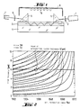
- Figure 1 shows an apparatus used for measuring polar molecules in the vapor phase of a liquid in accordance with the present invention.
- Figure 2 is a plot of film thickness ( ⁇ m) versus effective refractive index (N eff ,) for determining at what film thickness of HFDA-ODA (not according to the invention) the mode matching for the TE and TM polarizations may be obtained.
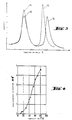
- Figure 3 is a plot of intensity versus coupling-in angle ( ⁇ ) depicting the TE/TM intersection point determined from the graph in Figure 2.
- Figure 4 is a calibration curve representing the birefringence alteration ( ⁇ N eff .10 ⁇ 3) and its correspondence to air humidity, illustrated by the use of HFDA-ODA for the polyimide waveguide material (not according to the invention).
- Figure 5 is a plot of the time dependance of the measured birefringence alteration, ⁇ N eff , for water on an HFDA-ODA waveguide (not according to the invention).
- Figure 6 is a plot of the anisotropic reaction, birefringence alteration ⁇ N eff .10 ⁇ 5 versus time [s], of an HFDA-HFDAM-33 three-layer waveguide (not according to the invention) when enriched with a mixture of water and methanol.
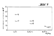
- Figure 7 is a plot of birefringence alteration ⁇ N eff .10 ⁇ 5 versus various index matching modes, m TE /m TM , for a four-layer waveguide consisting of HFDA-HFDAM-33/HFDA-HFDAM-44 on glass illustrating the increased sensitivity obtained with certain matched modes.
- Figure 8 depicts the structural arrangement for both three (not according to the invention) and four layer polyimide optical waveguides.
- one embodiment which may be used is the apparatus shown in Figure 1.
- the light of He-Ne laser (1) passes through half-wave plate (2), which polarizes the light at 45° (such that the TE and TM modes are equal) and rotates the TE and TM the polarization modes, at a particular angle of incidence, ⁇ , onto a polyimide waveguide which is composed of a substrate (4) coated with a polyimide film (3).
- the substrate is a substance which has a refractive index which is lower than that of the polyimides so the light is reflected up into the polyimide. Glass is a suitable substrate.
- 90° prisms made of heavy flint glass (5) are used to adjust the angle of incidence of the laser beam and couple the TM and TE modes into and out of the waveguide.
- the TM and TE modes coupled into the polyimide film (3) which may typically have a length of several centimeters, preferably, about 2 cm., is reflected to the surface (S) of the film where it contacts the vapor of the liquid and there is an optical anisotropic interaction which shifts the phase of the TM and TE modes.
- the TM and TE modes are coupled out of the film (3) by heavy flint glass prism (5′) and pass through an analyzer (6) which detects the alteration of the TM and TE modes.
- the analyzer (6) may be set at an angle of 90° to the direction of polarization so it can detect disturbances of the phase of the TM and TE modes.
- the detector (7) receives the signal of disturbance from the analyzer (6) and measures absolute intensity of the phase change, called the birefringence alteration, and converts the optical signal to an electrical signal which can then be displayed by any known means.
- the apparatus may be enclosed with a glass bell (8), which contains silica gel (9) in order to reduce the humidity in the apparatus which is due to the atmospheric humidity to illustrate the sensitivity of the device to changes in humidity.
- the moisture sensor should transmit a particular TE mode (e.g., TE5) and a matched TM mode (e.g., TM6) polarization simultaneously.
- TE5 and TM6 can be selected for transmittal through the waveguide by adjusting the angles of incidence ⁇ .
- the moisture sensor is constructed by utilizing the theoretical curves (Figure 2) computed from the substantive refractive index parameters for TE and TM. In this case, Figure 2 plots these curves for HFDA-ODA.
- the curves shown in Figure 2 plot the film thickness of the waveguide [ ⁇ m] against the effective refractive index N eff , of the appropriate TE and TM modes.
- These families of curves for the TE and TM polarizations represent the resonance conditions which arise from the transverse resonance condition (TRC) for plane waveguides.
- TRC transverse resonance condition
- the TE and TM modes must be matched for a particular film thickness.
- the desired property of matching of modes exists at a point of intersection of the TM and TE curves. For instance, the point of intersection indicated in Figure 2 corresponds to the matched modes for TE5 and TM6 at a film thickness of 6.1 ⁇ m for HFDA-ODA.
- Figure 3 depicts the intensity of the optical signal for modes TM5 and TE6, and TM6 and TE7, plotted against the coupling-in angle ⁇ , for an extract of the measured mode spectrum (Figure 2) of an anisotropic polyimide film HFDA-ODA having a layer thickness of 6.1 ⁇ m. It is at this film thickness as shown in Figure 2 that the TM5 and TE6 modes will be matched.
- the representation shows the TE6 mode (10) and the TM5 mode (11) which can be coupled at the same angle of incidence. The two modes overlap to such an extent that there will be sufficient overlapping of the matched modes even after the anisotropic interactions force the modes out of phase. The intensity is therefore still strong enough to be measured.
- the figure also shows that the TE7 and TM6 modes are out of phase, and therefore not matched, for the HFDA polyimide having a thickness of 6.1 ⁇ m.
- the period of time represented in Figure 3 is the initial state (of the vapor phase) before measuring the birefringence alteration.
- the overlapping of the TE and TM modes shown in Figure 3 is undertaken experimentally by preparing a waveguide having the thickness selected from the point of intersection in Figure 2.
- the film thickness is obtained by selecting a specific centrifuging speed of rotation on the photoresist centrifuge employed for producing a film from a polyimide solution.
- the surrounding atmosphere of a four-layer waveguide composed of an HFDA-HFDAM-33/HFDA-HFDAM-44 double layer was enriched with a mixture of methanol and water, whereupon the sensor reacted in the first instance to water with a specified rate constant and then to the alcohol.
- FIG. 6 depicts birefringence alteration ⁇ N eff .10 ⁇ 5 plotted against the time [s] for a three-layer waveguide (not according to the invention) using HFDA-HFDAM-33. It was observed that the curve adopts a different curve for water (14) as compared with methanol (15).
- the sensor responds to methanol with a differential sensitivity ( ⁇ N eff /t) which varies from its sensitivity to water, thereby enabling water to be separately distinguished from methanol. Time is indicated in seconds.
- C is a constant relating to the concentration of the molecule
- d is the diffusion coefficient for a particular type of molecule
- t is the time.
- the curve will be characteristic for each different molecule and will permit the identification of different molecules.
- the concentration of the molecule can be obtained by comparing the birefringence alteration at equilibrium for the molecule in the mixture (such as in Figure 6) with the corresponding birefringence alteration in the calibration curve for that molecule (such as in Figure 4). The concentration of that molecule in the sample being analyzed can be read from the calibration curve.
- the detector (7) of Figure 1 By providing the detector (7) of Figure 1 with a memory containing the data to produce calibration curves of the specific molecules to be analyzed and the capability to generate data for the birefringence alteration over time, the birefringence alteration at the equilibrium point for a particular molecule can be determined and a comparison with the calibration curve can be made to generate automatically the identity of the molecule and its concentration.
- Figure 7 shows a plot of the birefringence alteration ⁇ N eff .10 ⁇ 5 versus m TE /m TM , which is matched modes for TE and TM modes, at a relative air humidity of 42% (16) and in the evacuated condition (17) for an HFDA-HFDAM-33/HFDA-HFDAM-44 four-layer waveguide.
- the symbol, "m" represents the "mode order" with respect to TE and TM.
- surface modes is intended to refer to m TM ⁇ 2 in which the modes exhibit at the surface an especially high intensity and thus a high evanescent field.
- "space modes” show a high intensity in the interior of the film and only a weak evanescent field at the surface and m TM > 2.
- the space modes are transmitted through both layers of the polyimide.
- the four-layer polyimide sensor described in Example 3 was surrounded with a closed container.
- the volume of air enclosed (20°C, 65% RH) was then enriched with ethanol vapor. In this case, it was possible to detect less than 3 ⁇ 1/m3 C2H5OH.
- the sensitivity limit was at a level of 1 ml/m3 C3H7OH.
Landscapes
- Physics & Mathematics (AREA)
- General Physics & Mathematics (AREA)
- Chemical & Material Sciences (AREA)
- Health & Medical Sciences (AREA)
- Life Sciences & Earth Sciences (AREA)
- Analytical Chemistry (AREA)
- Biochemistry (AREA)
- General Health & Medical Sciences (AREA)
- Immunology (AREA)
- Pathology (AREA)
- Engineering & Computer Science (AREA)
- Optics & Photonics (AREA)
- Microelectronics & Electronic Packaging (AREA)
- Chemical Kinetics & Catalysis (AREA)
- Plasma & Fusion (AREA)
- Investigating Or Analysing Materials By Optical Means (AREA)
- Optical Integrated Circuits (AREA)
- Optical Fibers, Optical Fiber Cores, And Optical Fiber Bundles (AREA)
- Light Guides In General And Applications Therefor (AREA)
- Optical Couplings Of Light Guides (AREA)
- Compositions Of Macromolecular Compounds (AREA)
- Macromolecular Compounds Obtained By Forming Nitrogen-Containing Linkages In General (AREA)
Claims (12)
- Polyimidwellenleiter als optischer Sensor für die Bestimmung von Flüssigkeiten in der Dampfphase, welcher Wellenleiter für einen Kontakt mit einer Deckschicht aus Flüssigkeitsdampf an der Oberfläche (S) des Wellenleiters adaptiert ist, dadurch gekennzeichnet, daß der Polyimidwellenleiter aus wenigstens zwei Schichten aus einem Polyamidimid oder perfluoriertem Polyimid (3) besteht, die ein Substrat (4) überziehen und worin der Brechungsindex (nTM) für die transversale magnetische Polarisation (TM) der oberen Schicht des Polyimidwellenleiters größer ist als nTM der unteren Schicht und der Brechungsindex (nTE) für die transversale elektrische Polarisation (TE) der oberen Schicht etwa gleich groß ist wie nTE der unteren Schicht.
- Polyimidwellenleiter als optischer Sensor nach Anspruch 1, dadurch gekennzeichnet, daß die Schichtenanordnung Deckschicht/HFDA-HFDAM-33/HFDA-HFDAM-44/Substrat ist, worin HFDA-HFDAM-33 Hexafluoro-iso-propyliden-2,2′-di(3-aminobenzol) bedeutet und HFDA-HFDAM-44 Hexafluoro-iso-propyliden-2,2′-di(4-aminobenzol) bedeutet, die Deckschicht den Gasraum bedeutet und das Substrat Glas bedeutet.
- Polyimidwellenleiter als optischer Sensor nach Anspruch 1, dadurch gekennzeichnet, daß er in Form von Streifenwellenleitern, Interferometerstrukturen oder Richtkopplerstrukturen für die Bestimmung von Flüssigkeiten in der Dampfphase vorliegt.
- Polyimidwellenleiter nach Anspruch 1, dadurch gekennzeichnet, daß das Substrat Glas ist und das Polyamidimid oder perfluorierte Polyimid HFDA-ODA, HFDAM-33, HFDA-HFDAM-44 oder eine Kombination aus HFDA-HFDAM-33 und HFDA-HFDAM-44 ist.
- Vorrichtung zum Feststellen des Vorliegens von und zum Messen der Relativmenge eines Moleküls in einem Dampf, umfassend Mittel zum Richten eines polarisierten Lichtes auf den Polyimidwellenleiter und Einkuppeln des polarisierten Lichtes in den Wellenleiter;
einen der Oberfläche des Polyimidwellenleiters benachbarten Bereich zur Aufnahme des Dampfes der Flüssigkeit, so daß der Dampf mit dem Wellenleiter in Kontakt steht;
Mittel zum Auskuppeln des polarisierten Lichtes aus dem Polyimidwellenleiter und Mittel zum Messen der Intensität der Phasenverschiebung des polarisierten Lichtes, dadurch gekennzeichnet, daß sie einen Polyimidwellenleiter umfaßt, der im wesentlichen aus wenigstens zwei Schichten aus einem Polyamidimid oder perfluoriertem Polyimid besteht, die ein Substrat überziehen, wobei der Brechungsindex (nTM) für die transversale magnetische Polarisation (TM) der oberen Schicht des Polyimidwellenleiters größer ist als nTM der unteren Schicht und der Brechungsindex (nTE) für die transversale elektrische Polarisation (TE) der oberen Schicht etwa gleich groß ist wie nTE der unteren Schicht. - Vorrichtung nach Anspruch 5, dadurch gekennzeichnet, daß die Mittel zum Richten von polarisiertem Licht Mittel zum Richten von TM- und TE-Moden des polarisierten Lichtes umfassen.
- Vorrichtung nach Anspruch 5, dadurch gekennzeichnet, daß die Mittel zum Richten des polarisierten Lichtes Mittel zum Richten von TM- und TE-Moden des polarisierten Lichtes bei einem Winkel von etwa 45° umfassen.
- Vorrichtung nach Anspruch 7, dadurch gekennzeichnet, daß das Substrat einen Brechungsindex aufweist, der kleiner ist als derjenige des Polyamidimids oder perfluorierten Polyimids.
- Vorrichtung nach Anspruch 8, dadurch gekennzeichnet, daß das Polyamidimid oder perfluorierte Polyimid aus der aus HFDA-ODA, HFDA-HFDAM-33, HFDA-HFDAM-44 oder Kombinationen von HFDA-HFDAM-33 und HFDA-HFDAM-44 bestehenden Gruppe ausgewählt ist.
- Verwendung eines Polyimidwellenleiters als optischer Sensor nach Anspruch 1, für die Bestimmung von Wasser, C₁-C₃-Alkoholen, Benzin, leichtem Heizöl und C₁-C₃-Carbonsäuren in der Dampfphase.
- Verwendung eines Polyimidwellenleiters als optischer Sensor nach Anspruch 1, für die Bestimmung von NH3, "NH₄OH", NO₂ und N₂O₅ .
- Verwendung eines Polyimidwellenleiters nach den Ansprüchen 10 und 11, dadurch gekennzeichnet, daß er für die Modulation oder Messung von Einflüssen, die sich auf das Gleichgewicht an der Polyimidoberfläche und dem Meßraum auswirken, wie Druckschwankungen, elektrische Felder und Mikrowellen, verwendet wird.
Applications Claiming Priority (3)
| Application Number | Priority Date | Filing Date | Title |
|---|---|---|---|
| DE3926604A DE3926604A1 (de) | 1989-08-11 | 1989-08-11 | Polyimidwellenleiter als optische sensoren |
| DE3926604 | 1989-08-11 | ||
| PCT/EP1990/001327 WO1991002239A1 (en) | 1989-08-11 | 1990-08-11 | Polyimide waveguides as optical sensors |
Publications (2)
| Publication Number | Publication Date |
|---|---|
| EP0486597A1 EP0486597A1 (de) | 1992-05-27 |
| EP0486597B1 true EP0486597B1 (de) | 1994-09-14 |
Family
ID=6386968
Family Applications (1)
| Application Number | Title | Priority Date | Filing Date |
|---|---|---|---|
| EP90912918A Expired - Lifetime EP0486597B1 (de) | 1989-08-11 | 1990-08-11 | Polyimidwellenleiter als optische sensoren |
Country Status (10)
| Country | Link |
|---|---|
| US (1) | US5094517A (de) |
| EP (1) | EP0486597B1 (de) |
| JP (1) | JPH03183935A (de) |
| KR (1) | KR920004868A (de) |
| CN (1) | CN1049720A (de) |
| AT (1) | ATE111600T1 (de) |
| AU (1) | AU6280190A (de) |
| CA (2) | CA2023072A1 (de) |
| DE (2) | DE3926604A1 (de) |
| WO (1) | WO1991002239A1 (de) |
Families Citing this family (42)
| Publication number | Priority date | Publication date | Assignee | Title |
|---|---|---|---|---|
| US5168542A (en) * | 1991-10-09 | 1992-12-01 | The Boeing Company | Low loss channel waveguide and method for making the same |
| US5315673A (en) * | 1992-03-09 | 1994-05-24 | Transducer Research, Inc. | Optical waveguide vapor sensor |
| US5483346A (en) * | 1994-04-11 | 1996-01-09 | Butzer; Dane C. | Polarization based optical sensor utilizing total internal reflection |
| JP2807777B2 (ja) * | 1994-09-09 | 1998-10-08 | 工業技術院長 | スラブ光導波路を利用した光吸収スペクトル測定装置 |
| US5577137A (en) * | 1995-02-22 | 1996-11-19 | American Research Corporation Of Virginia | Optical chemical sensor and method using same employing a multiplicity of fluorophores contained in the free volume of a polymeric optical waveguide or in pores of a ceramic waveguide |
| US5745231A (en) * | 1995-06-12 | 1998-04-28 | American Research Corporation Of Virginia | Method of fluorescence analysis comprising evanescent wave excitation and out-of-plane photodetection |
| JP3738469B2 (ja) * | 1995-07-27 | 2006-01-25 | 日立化成工業株式会社 | ポリイミド及びこれを用いた光部品 |
| US7187795B2 (en) * | 2001-09-27 | 2007-03-06 | Cummins-Allison Corp. | Document processing system using full image scanning |
| US6149591A (en) * | 1997-02-21 | 2000-11-21 | Duke University | Refractometric devices especially adapted for the in vivo detection of refractive indices of cervical mucus |
| DE19716252A1 (de) * | 1997-04-18 | 1998-10-22 | Conducta Endress & Hauser | Optischer Sensor |
| WO1999001737A2 (en) * | 1997-06-10 | 1999-01-14 | Calspan Corporation | Detection of chemical agent materials using a sorbent polymer and fluorescent probe |
| US6850315B1 (en) | 1998-08-26 | 2005-02-01 | The Board Of Governors For Higher Education State Of Rhode Island And Providence Plantations | Intensity-based optical waveguide sensor |
| US6300638B1 (en) | 1998-11-12 | 2001-10-09 | Calspan Srl Corporation | Modular probe for total internal reflection fluorescence spectroscopy |
| US6438279B1 (en) * | 1999-01-07 | 2002-08-20 | Cornell Research Foundation, Inc. | Unitary microcapiliary and waveguide structure and method of fabrication |
| EP1256819A4 (de) * | 1999-10-28 | 2006-08-23 | Sharp Kk | Optisches bauelement und verfahren zur herstellung eines polyimid-dickfilms |
| GB9927248D0 (en) | 1999-11-18 | 2000-01-12 | Farfield Sensors Ltd | Sensor device |
| KR20010087502A (ko) | 2000-03-07 | 2001-09-21 | 윤종용 | 광학용 폴리이미드 단량체, 폴리이미드 화합물 및 그 제조방법 |
| EP1221581A1 (de) * | 2001-01-04 | 2002-07-10 | Universität Stuttgart | Interferometer |
| KR20020082514A (ko) * | 2001-04-24 | 2002-10-31 | 주식회사 씨앤케이 | 광 상관기 |
| US6917749B2 (en) | 2001-11-07 | 2005-07-12 | Photon-X, Llc | Polymer optical waveguides on polymer substrates |
| US6603917B2 (en) | 2001-11-07 | 2003-08-05 | Photon-X, Inc | Planar optical waveguide with core barrier |
| US6903815B2 (en) * | 2001-11-22 | 2005-06-07 | Kabushiki Kaisha Toshiba | Optical waveguide sensor, device, system and method for glucose measurement |
| US20050018944A1 (en) * | 2003-07-25 | 2005-01-27 | Mozdy Eric J. | Polarization modulation interrogation of grating-coupled waveguide sensors |
| DE102005055288A1 (de) * | 2005-10-17 | 2007-04-19 | Universität Duisburg-Essen | Sensor und Verfahren zur optischen Detektion eines chemischen Stoffs |
| WO2008028160A2 (en) | 2006-09-01 | 2008-03-06 | Pacific Biosciences Of California, Inc. | Substrates, systems and methods for analyzing materials |
| US8207509B2 (en) | 2006-09-01 | 2012-06-26 | Pacific Biosciences Of California, Inc. | Substrates, systems and methods for analyzing materials |
| EP2331934B1 (de) | 2008-09-16 | 2020-01-01 | Pacific Biosciences of California, Inc. | Analysegerät mit Nullmoden-Wellenleiter Substrat |
| JP2010223817A (ja) * | 2009-03-24 | 2010-10-07 | Soka Univ | エタノールセンサ及びこれを用いたエタノール計測システム |
| US8994946B2 (en) | 2010-02-19 | 2015-03-31 | Pacific Biosciences Of California, Inc. | Integrated analytical system and method |
| EP3460458B1 (de) | 2010-02-19 | 2021-08-11 | Pacific Biosciences of California, Inc. | Verfahren zur nukleinsäuresequenzierung |
| US9372308B1 (en) | 2012-06-17 | 2016-06-21 | Pacific Biosciences Of California, Inc. | Arrays of integrated analytical devices and methods for production |
| EP2936222B1 (de) | 2012-12-18 | 2019-07-03 | Pacific Biosciences Of California, Inc. | Eine optische analysevorrichtung |
| US9624540B2 (en) | 2013-02-22 | 2017-04-18 | Pacific Biosciences Of California, Inc. | Integrated illumination of optical analytical devices |
| TWI692633B (zh) | 2014-08-27 | 2020-05-01 | 美商加州太平洋生物科學公司 | 整合式分析裝置之陣列 |
| EP3271762B1 (de) | 2015-03-16 | 2023-01-04 | Pacific Biosciences of California, Inc. | Analysesystem umfassend integrierte vorrichtungen und systeme zur optischen freiraumkopplung |
| EP3292220B1 (de) | 2015-05-07 | 2022-07-13 | Pacific Biosciences of California, Inc. | Multiprozessor-pipeline-architektur |
| EP4425153A3 (de) | 2015-06-12 | 2024-11-20 | Pacific Biosciences Of California, Inc. | Integrierte zielwellenleitervorrichtungen und systeme zur optischen kopplung |
| US10407296B2 (en) | 2016-10-12 | 2019-09-10 | Knappco Corporation | Optical fluid sensors for cross contamination control systems |
| US12535420B2 (en) | 2020-02-18 | 2026-01-27 | Pacific Biosciences Of California, Inc. | Highly multiplexed nucleic acid sequencing systems |
| KR20240006033A (ko) | 2021-05-04 | 2024-01-12 | 퍼시픽 바이오사이언스 오브 캘리포니아, 인크. | 축소된 규모의 단위 셀을 갖는 통합 분석 장치의 어레이 |
| CN115128735B (zh) * | 2021-10-27 | 2024-05-07 | 赛丽科技(苏州)有限公司 | 光学传感器芯片和光学传感系统 |
| CN117072892A (zh) * | 2023-08-14 | 2023-11-17 | 北京中自控创新科技发展有限公司 | 一种用于燃气泄漏巡检的光纤式监测系统及方法 |
Family Cites Families (2)
| Publication number | Priority date | Publication date | Assignee | Title |
|---|---|---|---|---|
| JPS5595902A (en) * | 1978-11-30 | 1980-07-21 | Daicel Chem Ind Ltd | Optical fiber for transmission |
| EP0403468A1 (de) * | 1988-02-14 | 1990-12-27 | LUKOSZ, Walter | Integriert-optisches interferenzverfahren |
-
1989
- 1989-08-11 DE DE3926604A patent/DE3926604A1/de not_active Withdrawn
-
1990
- 1990-08-09 KR KR1019900012196A patent/KR920004868A/ko active Pending
- 1990-08-10 JP JP2213612A patent/JPH03183935A/ja active Pending
- 1990-08-10 CN CN90106947A patent/CN1049720A/zh active Pending
- 1990-08-10 CA CA002023072A patent/CA2023072A1/en not_active Abandoned
- 1990-08-10 US US07/565,503 patent/US5094517A/en not_active Expired - Lifetime
- 1990-08-11 EP EP90912918A patent/EP0486597B1/de not_active Expired - Lifetime
- 1990-08-11 DE DE69012573T patent/DE69012573T2/de not_active Expired - Fee Related
- 1990-08-11 CA CA002064831A patent/CA2064831A1/en not_active Abandoned
- 1990-08-11 AT AT90912918T patent/ATE111600T1/de not_active IP Right Cessation
- 1990-08-11 AU AU62801/90A patent/AU6280190A/en not_active Abandoned
- 1990-08-11 WO PCT/EP1990/001327 patent/WO1991002239A1/en not_active Ceased
Also Published As
| Publication number | Publication date |
|---|---|
| CA2023072A1 (en) | 1991-02-12 |
| EP0486597A1 (de) | 1992-05-27 |
| DE3926604A1 (de) | 1991-02-14 |
| DE69012573D1 (de) | 1994-10-20 |
| US5094517A (en) | 1992-03-10 |
| CN1049720A (zh) | 1991-03-06 |
| AU6280190A (en) | 1991-03-11 |
| CA2064831A1 (en) | 1991-02-12 |
| ATE111600T1 (de) | 1994-09-15 |
| DE69012573T2 (de) | 1995-02-23 |
| KR920004868A (ko) | 1992-03-28 |
| WO1991002239A1 (en) | 1991-02-21 |
| JPH03183935A (ja) | 1991-08-09 |
Similar Documents
| Publication | Publication Date | Title |
|---|---|---|
| EP0486597B1 (de) | Polyimidwellenleiter als optische sensoren | |
| Jorgenson et al. | Control of the dynamic range and sensitivity of a surface plasmon resonance based fiber optic sensor | |
| US4950074A (en) | Method of determining the refractive index of a substance and apparatus thereof | |
| Nelson et al. | High sensitivity surface plasmon resonace sensor based on phase detection | |
| Meeten | Refractive index errors in the critical-angle and the Brewster-angle methods applied to absorbing and heterogeneous materials | |
| WO2001088509A1 (en) | Coupled plasmon-waveguide resonance spectroscopic device | |
| GB2340231A (en) | Optical transducers based on liquid crystalline phases | |
| Ronot-Trioli et al. | Fibre optic chemical sensor based on surface plasmon monochromatic excitation | |
| Gu et al. | Design optimization of a long-period fiber grating with sol–gel coating for a gas sensor | |
| WO2002014841A1 (en) | Sensor device | |
| US5644125A (en) | Spectrometer employing a Mach Zehnder interferometer created by etching a waveguide on a substrate | |
| Räty et al. | The complex refractive index measurement of liquids by a novel reflectometer apparatus for the UV-visible spectral range | |
| Abdurahman et al. | Optical waveguide sensor of volatile organic compounds based on PTA thin film | |
| Podgorsek et al. | Optical detection of water/alcohol vapours by polymide lightguides | |
| CN102262073A (zh) | 一种基于波导耦合表面等离子共振的降低背景影响的检测方法 | |
| Räty et al. | Measurement of refractive index of liquids using s-and p-polarized light | |
| JP2894829B2 (ja) | 光学センサーとしてのポリイミド導波管 | |
| Tubb et al. | Single mode optical fibre surface plasma wave chemical sensor | |
| CN109709068A (zh) | 调谐长程spr器件及利用该器件检测折射率的方法 | |
| EP0766816B1 (de) | Optischer gassensor | |
| Matsuda et al. | Polarization property associated with surface plasmon resonance in a metal grating in a conical mounting and its application to refractive index sensing | |
| Ingenhoff et al. | Spectral interferometric sensors for gases and liquids using integrated optical devices | |
| Hanisch et al. | Origin of optical anisotropy in planar polymer waveguides | |
| Moreno-Bondi et al. | Fibre optic sensors for humidity monitoring | |
| Dolzhenko et al. | TFBG-assisted fiber optic sensors for environmental monitoring |
Legal Events
| Date | Code | Title | Description |
|---|---|---|---|
| PUAI | Public reference made under article 153(3) epc to a published international application that has entered the european phase |
Free format text: ORIGINAL CODE: 0009012 |
|
| 17P | Request for examination filed |
Effective date: 19920128 |
|
| AK | Designated contracting states |
Kind code of ref document: A1 Designated state(s): AT BE CH DE DK ES FR GB IT LI LU NL SE |
|
| 17Q | First examination report despatched |
Effective date: 19931220 |
|
| GRAA | (expected) grant |
Free format text: ORIGINAL CODE: 0009210 |
|
| AK | Designated contracting states |
Kind code of ref document: B1 Designated state(s): AT BE CH DE DK ES FR GB IT LI LU NL SE |
|
| PG25 | Lapsed in a contracting state [announced via postgrant information from national office to epo] |
Ref country code: NL Effective date: 19940914 Ref country code: ES Free format text: THE PATENT HAS BEEN ANNULLED BY A DECISION OF A NATIONAL AUTHORITY Effective date: 19940914 Ref country code: DK Effective date: 19940914 Ref country code: BE Effective date: 19940914 Ref country code: AT Effective date: 19940914 |
|
| REF | Corresponds to: |
Ref document number: 111600 Country of ref document: AT Date of ref document: 19940915 Kind code of ref document: T |
|
| REF | Corresponds to: |
Ref document number: 69012573 Country of ref document: DE Date of ref document: 19941020 |
|
| ITF | It: translation for a ep patent filed | ||
| PG25 | Lapsed in a contracting state [announced via postgrant information from national office to epo] |
Ref country code: SE Effective date: 19941214 |
|
| ET | Fr: translation filed | ||
| NLV1 | Nl: lapsed or annulled due to failure to fulfill the requirements of art. 29p and 29m of the patents act | ||
| PLBE | No opposition filed within time limit |
Free format text: ORIGINAL CODE: 0009261 |
|
| STAA | Information on the status of an ep patent application or granted ep patent |
Free format text: STATUS: NO OPPOSITION FILED WITHIN TIME LIMIT |
|
| PG25 | Lapsed in a contracting state [announced via postgrant information from national office to epo] |
Ref country code: LU Free format text: LAPSE BECAUSE OF NON-PAYMENT OF DUE FEES Effective date: 19950831 Ref country code: LI Effective date: 19950831 Ref country code: CH Effective date: 19950831 |
|
| 26N | No opposition filed | ||
| REG | Reference to a national code |
Ref country code: CH Ref legal event code: PL |
|
| REG | Reference to a national code |
Ref country code: GB Ref legal event code: IF02 |
|
| PGFP | Annual fee paid to national office [announced via postgrant information from national office to epo] |
Ref country code: GB Payment date: 20040730 Year of fee payment: 15 |
|
| PGFP | Annual fee paid to national office [announced via postgrant information from national office to epo] |
Ref country code: DE Payment date: 20040805 Year of fee payment: 15 |
|
| PGFP | Annual fee paid to national office [announced via postgrant information from national office to epo] |
Ref country code: FR Payment date: 20040809 Year of fee payment: 15 |
|
| PG25 | Lapsed in a contracting state [announced via postgrant information from national office to epo] |
Ref country code: IT Free format text: LAPSE BECAUSE OF NON-PAYMENT OF DUE FEES;WARNING: LAPSES OF ITALIAN PATENTS WITH EFFECTIVE DATE BEFORE 2007 MAY HAVE OCCURRED AT ANY TIME BEFORE 2007. THE CORRECT EFFECTIVE DATE MAY BE DIFFERENT FROM THE ONE RECORDED. Effective date: 20050811 Ref country code: GB Free format text: LAPSE BECAUSE OF NON-PAYMENT OF DUE FEES Effective date: 20050811 |
|
| PG25 | Lapsed in a contracting state [announced via postgrant information from national office to epo] |
Ref country code: DE Free format text: LAPSE BECAUSE OF NON-PAYMENT OF DUE FEES Effective date: 20060301 |
|
| GBPC | Gb: european patent ceased through non-payment of renewal fee |
Effective date: 20050811 |
|
| PG25 | Lapsed in a contracting state [announced via postgrant information from national office to epo] |
Ref country code: FR Free format text: LAPSE BECAUSE OF NON-PAYMENT OF DUE FEES Effective date: 20060428 |
|
| REG | Reference to a national code |
Ref country code: FR Ref legal event code: ST Effective date: 20060428 |