EP0486657B1 - Accelerometre a flexions isoles - Google Patents
Accelerometre a flexions isoles Download PDFInfo
- Publication number
- EP0486657B1 EP0486657B1 EP91911128A EP91911128A EP0486657B1 EP 0486657 B1 EP0486657 B1 EP 0486657B1 EP 91911128 A EP91911128 A EP 91911128A EP 91911128 A EP91911128 A EP 91911128A EP 0486657 B1 EP0486657 B1 EP 0486657B1
- Authority
- EP
- European Patent Office
- Prior art keywords
- support
- accelerometer
- paddle
- mounting
- reed
- Prior art date
- Legal status (The legal status is an assumption and is not a legal conclusion. Google has not performed a legal analysis and makes no representation as to the accuracy of the status listed.)
- Expired - Lifetime
Links
- 238000002955 isolation Methods 0.000 title abstract description 6
- 235000014676 Phragmites communis Nutrition 0.000 claims abstract description 24
- 230000001133 acceleration Effects 0.000 claims description 9
- 230000004044 response Effects 0.000 claims description 4
- 238000000034 method Methods 0.000 abstract description 6
- 238000013459 approach Methods 0.000 description 6
- 230000036316 preload Effects 0.000 description 6
- 239000003990 capacitor Substances 0.000 description 4
- 239000000919 ceramic Substances 0.000 description 4
- VYPSYNLAJGMNEJ-UHFFFAOYSA-N Silicium dioxide Chemical compound O=[Si]=O VYPSYNLAJGMNEJ-UHFFFAOYSA-N 0.000 description 2
- 230000008859 change Effects 0.000 description 2
- 238000006073 displacement reaction Methods 0.000 description 2
- 230000005284 excitation Effects 0.000 description 2
- 230000007935 neutral effect Effects 0.000 description 2
- 230000035945 sensitivity Effects 0.000 description 2
- 238000005299 abrasion Methods 0.000 description 1
- 238000005452 bending Methods 0.000 description 1
- 230000008901 benefit Effects 0.000 description 1
- 230000008878 coupling Effects 0.000 description 1
- 238000010168 coupling process Methods 0.000 description 1
- 238000005859 coupling reaction Methods 0.000 description 1
- 238000009826 distribution Methods 0.000 description 1
- 238000005530 etching Methods 0.000 description 1
- 239000005350 fused silica glass Substances 0.000 description 1
- 238000003698 laser cutting Methods 0.000 description 1
- 230000008569 process Effects 0.000 description 1
- 239000010453 quartz Substances 0.000 description 1
- XLYOFNOQVPJJNP-UHFFFAOYSA-N water Substances O XLYOFNOQVPJJNP-UHFFFAOYSA-N 0.000 description 1
- 238000003466 welding Methods 0.000 description 1
Images

Classifications
-
- G—PHYSICS
- G01—MEASURING; TESTING
- G01P—MEASURING LINEAR OR ANGULAR SPEED, ACCELERATION, DECELERATION, OR SHOCK; INDICATING PRESENCE, ABSENCE, OR DIRECTION, OF MOVEMENT
- G01P15/00—Measuring acceleration; Measuring deceleration; Measuring shock, i.e. sudden change of acceleration
- G01P15/02—Measuring acceleration; Measuring deceleration; Measuring shock, i.e. sudden change of acceleration by making use of inertia forces using solid seismic masses
- G01P15/08—Measuring acceleration; Measuring deceleration; Measuring shock, i.e. sudden change of acceleration by making use of inertia forces using solid seismic masses with conversion into electric or magnetic values
- G01P15/13—Measuring acceleration; Measuring deceleration; Measuring shock, i.e. sudden change of acceleration by making use of inertia forces using solid seismic masses with conversion into electric or magnetic values by measuring the force required to restore a proofmass subjected to inertial forces to a null position
- G01P15/132—Measuring acceleration; Measuring deceleration; Measuring shock, i.e. sudden change of acceleration by making use of inertia forces using solid seismic masses with conversion into electric or magnetic values by measuring the force required to restore a proofmass subjected to inertial forces to a null position with electromagnetic counterbalancing means
-
- G—PHYSICS
- G01—MEASURING; TESTING
- G01P—MEASURING LINEAR OR ANGULAR SPEED, ACCELERATION, DECELERATION, OR SHOCK; INDICATING PRESENCE, ABSENCE, OR DIRECTION, OF MOVEMENT
- G01P15/00—Measuring acceleration; Measuring deceleration; Measuring shock, i.e. sudden change of acceleration
- G01P15/02—Measuring acceleration; Measuring deceleration; Measuring shock, i.e. sudden change of acceleration by making use of inertia forces using solid seismic masses
- G01P15/08—Measuring acceleration; Measuring deceleration; Measuring shock, i.e. sudden change of acceleration by making use of inertia forces using solid seismic masses with conversion into electric or magnetic values
- G01P2015/0805—Measuring acceleration; Measuring deceleration; Measuring shock, i.e. sudden change of acceleration by making use of inertia forces using solid seismic masses with conversion into electric or magnetic values being provided with a particular type of spring-mass-system for defining the displacement of a seismic mass due to an external acceleration
- G01P2015/0822—Measuring acceleration; Measuring deceleration; Measuring shock, i.e. sudden change of acceleration by making use of inertia forces using solid seismic masses with conversion into electric or magnetic values being provided with a particular type of spring-mass-system for defining the displacement of a seismic mass due to an external acceleration for defining out-of-plane movement of the mass
- G01P2015/0825—Measuring acceleration; Measuring deceleration; Measuring shock, i.e. sudden change of acceleration by making use of inertia forces using solid seismic masses with conversion into electric or magnetic values being provided with a particular type of spring-mass-system for defining the displacement of a seismic mass due to an external acceleration for defining out-of-plane movement of the mass for one single degree of freedom of movement of the mass
- G01P2015/0828—Measuring acceleration; Measuring deceleration; Measuring shock, i.e. sudden change of acceleration by making use of inertia forces using solid seismic masses with conversion into electric or magnetic values being provided with a particular type of spring-mass-system for defining the displacement of a seismic mass due to an external acceleration for defining out-of-plane movement of the mass for one single degree of freedom of movement of the mass the mass being of the paddle type being suspended at one of its longitudinal ends
Definitions
- the present invention relates to accelerometers in which a proof mass is mounted to a support by flexures.
- the accelerometer comprises three primary components, a reed, and upper and lower stators or magnetic circuits between which the reed is supported.
- the reed includes a movable paddle that is suspended via flexures to an outer annular support ring, such that the paddle can pivot with respect to the support ring.
- the paddle, flexures and support ring are commonly provided as a unitary structure composed of fused quartz.
- Both upper and lower surfaces of the paddle include capacitor plates and force balancing coils.
- Each force balancing coil is positioned on the paddle such that the central axis of the coil is normal to the top and bottom surfaces of the paddle, and parallel to the sensing axis of the accelerometer.
- a plurality of mounting pads are formed at spaced-apart positions around the upper and lower surfaces of the annular support ring. These mounting pads mate with inwardly facing surfaces of the upper and lower stators when the accelerometer is assembled.
- Each stator is generally cylindrical, and has a bore provided in its inwardly facing surface. Contained within the bore is a permanent magnet.
- the bore and permanent magnet are configured such that an associated one of the force balancing coils mounted on the paddle fits within the bore, with the permanent magnet being positioned within the cylindrical core of the coil. Current flowing through the coil therefore produces a magnetic field that interacts with the permanent magnet to produce a force on the paddle.
- capacitor plates are also provided on the inwardly facing surfaces of the stators configured to form capacitors with the capacitor plates on the top and bottom surface of the paddle.
- the accelerometer is affixed to an object whose acceleration is to be measured. Acceleration of the object along the sensing axis results in pendulous, rotational displacement of the paddle with respect to the support ring and the stators. The resulting differential capacitance change caused by this displacement is sensed by a feedback circuit. In response, the feedback circuit produces a current that, when applied to the force balancing coils, tends to return the paddle to its neutral position. The magnitude of the current required to maintain the paddle in its neutral position provides a measure of the acceleration along the sensing axis.
- Prior accelerometer designs of the type described above have in general taken two different approaches to the mounting of the reed.
- three mounting pads are equally spaced from one another around the support ring, and the reed is clamped between the stators via such mounting pads.
- This arrangement results in at least one mounting pad being close to the area of the support ring to which the flexures are attached. Mounting strains and thermal strains are therefore coupled into the flexures, causing bias sensitivities to mounting and temperature. Overall stability of the accelerometer is thus degraded.
- This design does have the advantage of providing three pads that are widely separated, with at least one pad on each side of the magnetic circuit centerline. Preload forces can therefore be applied at the center of the accelerometer, to provide a stable clamping condition.
- this first approach allows for flexibility in preload system design, but results in degraded bias performance.
- a second commonly used design approach involves the placement of all three mounting pads to one side of the centerline, as far as possible from the flexure area.
- the long support ring section between the mounting pads and the flexures provides isolation of the flexures from thermal strains and mounting strains.
- This approach also allows two of the mounting pads to be aligned with the centroid of pick-off capacitance, as taught in Patent US-A-4182187.
- this mounting pad arrangement resuilts in improved bias performance, but does not allow preloads to be applied at the centreline of the accelerometer, and may degrade alignment stability.
- International Patent Application WO-A-9000254 also discloses embodiments of an accelerometer employing various means for ensuring that the centroid of capacitance of the accelerometer paddle is not displaced when the accelerometer is subjected to stresses.
- One of these embodiments includes an arcuate slot dividing an area of the support ring into an inner portion, to which the paddle is attached, and an outer portion, by which the accelerometer is mounted.
- the present invention provides a technique for isolating the flexures from strains coupled into the reed through the mounting pads, in a way that permits use of low-cost, axial preloading techniques.
- An accelerometer for measuring acceleration along a sensing axis comprises a reed that includes a paddle, a support encircling the paddle and flexure means for providing a flexural connection between the paddle and the support so as to support the paddle for pivotal movement relative to the support in response to acceleration along the sensing axis.
- the support includes at least one mounting pad and the accelerometer further comprises means for contacting the mounting pads to mount the reed.
- An area of the support adjacent to the flexure means is divided by a slot into an inner portion and an outer portion.
- the flexure means are connected to the inner portion and no mounting pad is positioned on the inner portion, whereby the flexure means is isolated from stresses coupled into the reed through the mounting pads.
- a force transducer is connected between the inner portion of the support and the paddle.
- FIGURES 1-3 illustrate an accelerometer that includes a flexure isolation system.
- the accelerometer 10 measures acceleration along sensing axis SA, and includes stator 12, reed 14, ceramic plate 16, and electronic assembly 18, all mounted within an enclosure formed by mounting flange 20 and case 22.
- Reed 14 is held between ceramic plate 16 and stator 12, and has coil 24 positioned on its upper surface.
- Stator 12 in turn bears against case 22 via positioning ring 26 and spring washer 28.
- the stator comprises excitation ring 42, magnet 44 and pole piece 46.
- the stator is shaped so that coil 24 occupies a comparatively narrow gap between pole piece 46 and excitation ring 42, to provide the force balancing function well known to those skilled in the art.
- Ceramic plate 16 is held against reed 14 by inner shoulder 30 of mounting flange 20, and the mounting flange and case 22 are interconnected by welding or by any other suitable process.
- Means (not shown) are provided for electrically interconnecting electronics assembly 18 with reed 14, and for providing connections between the electronics assembly and an electrical connector on the outer surface of mounting flange 20.
- Reed 14 is shown in greater detail in FIGURES 2 and 3.
- the reed has an overall disk-like shape, and includes annular support ring 32 and paddle 34 connected to one another via a pair of flexures 36 positioned on opposite sides of opening 40. For most of its perimeter, paddle 34 is separated from support ring 32 by gap 38.
- Three raised mounting pads 50-52 are located at approximately equally spaced positions around support ring 32, and three similar mounting pads (not shown) are located immediately beneath the pads 50-52 on the lower surface of the support ring. In the assembled accelerometer, the upper mounting pads 50-52 contact stator 12, while the lower mounting pads contact ceramic plate 16.
- Paddle 34 is mounted via flexures 36 such that the paddle can pivot with respect to support ring 32 about hinge axis HA that passes through the flexures and that is horizontal and parallel to the plane of the drawing in FIGURE 2.
- a portion of support ring 32 adjacent to flexures 36 is divided by slot 70 into inner ring 72 and outer ring 74.
- Mounting pad 50 is positioned on outer ring 74 only, and the flexures are connected to inner ring 72. As a result of this arrangement, stress coupled into reed 14 via mounting pad 50 is isolated from flexures 36.
- Slot 70 can be manufactured by etching, air abrasion, water jet, laser cutting, or any other sutiable technique. Slot 70 preferably extends approximately halfway around the support ring 32. As the length of the slot is reduced, the degree of isolation is likewise reduced. On the other hand, as the slot length increases beyond the illustrated half-circumference length, inner ring 72 may become too flexible, leading to significant bending of the inner ring in response to acceleration.
- the described split support ring approach allows mounting pad 50 to be located near flexures 36, on outer ring 74, without creating direct mechanical coupling of the mounting pad to the flexure area of the support ring.
- the evenly spaced distribution of mounting pads 50-52 about the circumference of the support ring permits the centre of preload force to be located almost anywhere wiithin the diameter of the proof mass assembly.
- the preferred location is on centreline 62, to provide equal mounting pad loading. This low sensitivity with respect to the exact position of the centre of preload force allows the use of low-cost preload techniques, such as spring washer 28 shown in FIGURE 1.
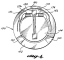
- FIGURE 4 A preferred embodiment of the invention is shown in FIGURE 4.
- This embodiment includes reed 150 that comprises annular support ring 152 and paddle 154 connected to one another by flexures 156.
- Mounting pads 160 are positioned on the support ring, in the same manner as shown in the embodiments of FIGURES 2-3.
- the support ring is divided by slot 170 into inner ring 172 and outer ring 174.
- the mounting pad 160 adjacent to flexures 156 is connected to outer ring 174 only.
- Force transducer 180 is connected between paddle 154 and a portion of inner ring 172 between flexures 156.
- the force transducer may comprise a conventional double-ended tuning fork crystalline quartz device.
- slot 170 serves to isolate the mounting pads from the point of connection of force transducer 180 to the support ring.
Landscapes
- Physics & Mathematics (AREA)
- Electromagnetism (AREA)
- General Physics & Mathematics (AREA)
- Pressure Sensors (AREA)
- General Electrical Machinery Utilizing Piezoelectricity, Electrostriction Or Magnetostriction (AREA)
Abstract
Claims (5)
- Accéléromètre pour mesurer l'accélération suivant un axe de détection (SA), l'accéléromètre comprenant une lame (150) qui comporte une palette (154), un support (152) entourant la palette et des moyens d'éléments souples (156) pour procurer une liaison souple entre la palette (154) et le support (152) de façon à supporter la palette pour mouvement pivotant par rapport au support en réponse à l'accélération suivant l'axe de détection (SA), le support (152) comportant au moins un atténuateur de fixation (160) et l'accéléromètre comprenant de plus un moyen de montage (12, 16) pour contacter les atténuateurs de fixation (160) afin de fixer la lame (150), dans lequel une zone du support (152) contiguë aux moyens d'éléments souples (156) est divisée par une fente (170) en une partie interne (172) et une partie externe (174), les moyens d'éléments souples (156) étant raccordés à la partie interne (172) et aucun atténuateur de fixation n'étant positionné sur la partie interne (172), d'où il résulte que les moyens d'éléments souples (156) sont isolés des contraintes couplées à la lame par l'intermédiaire des atténuateurs de fixation (160),
CARACTERISE EN CE QUE l'accéléromètre comprend de plus un transducteur de force (180) raccordé entre la partie interne (172) du support et la palette (154). - Accéléromètre selon la revendication 1, dans lequel la fente (170) s'étend en un arc approximativement à mi-chemin autour du support (152).
- Accéléromètre selon la revendication 1, dans lequel le support (152) comporte trois desdits atténuateurs de fixation (160), espacés approximativement de manière égale les uns des autres autour de celui-ci.
- Accéléromètre selon la revendication 3, dans lequel un seul atténuateur de fixation (160) est positionné sur la partie externe (174) du support (152), immédiatement contiguë aux moyens d'éléments souples (156) mais séparés de ceux-ci par la fente (170).
- Accéléromètre selon la revendication 4, dans lequel la fente (170) s'étend à partir d'une extrémité contiguë à un premier atténuateur de fixation parmi les atténuateurs de fixation (160), devant ledit atténuateur de fixation (160) contigu aux moyens d'éléments souples (156) jusqu'à une extrémité contiguë au troisième atténuateur de fixation (160).
Applications Claiming Priority (3)
| Application Number | Priority Date | Filing Date | Title |
|---|---|---|---|
| US53578590A | 1990-06-11 | 1990-06-11 | |
| US535785 | 1990-06-11 | ||
| PCT/US1991/003561 WO1991019986A1 (fr) | 1990-06-11 | 1991-05-20 | Accelerometer a elements souples isoles |
Publications (3)
| Publication Number | Publication Date |
|---|---|
| EP0486657A1 EP0486657A1 (fr) | 1992-05-27 |
| EP0486657A4 EP0486657A4 (en) | 1993-02-24 |
| EP0486657B1 true EP0486657B1 (fr) | 1994-12-28 |
Family
ID=24135757
Family Applications (1)
| Application Number | Title | Priority Date | Filing Date |
|---|---|---|---|
| EP91911128A Expired - Lifetime EP0486657B1 (fr) | 1990-06-11 | 1991-05-20 | Accelerometre a flexions isoles |
Country Status (6)
| Country | Link |
|---|---|
| US (1) | US5287744A (fr) |
| EP (1) | EP0486657B1 (fr) |
| JP (1) | JP3142292B2 (fr) |
| DE (1) | DE69106326T2 (fr) |
| IL (1) | IL98347A0 (fr) |
| WO (1) | WO1991019986A1 (fr) |
Cited By (7)
| Publication number | Priority date | Publication date | Assignee | Title |
|---|---|---|---|---|
| WO2016109807A1 (fr) | 2015-01-02 | 2016-07-07 | Hello, Inc. | Dispositif de surveillance de chambre et analyse du sommeil |
| US10826699B2 (en) | 2018-06-15 | 2020-11-03 | Proxy, Inc. | High availability BLE proximity detection methods and apparatus |
| US11109234B2 (en) | 2018-06-15 | 2021-08-31 | Proxy, Inc. | Reader device with sensor streaming data and methods |
| US11411735B2 (en) | 2018-06-15 | 2022-08-09 | Proxy, Inc. | Methods and apparatus for authorizing and providing of distributed goods or services |
| US11438767B2 (en) | 2018-06-15 | 2022-09-06 | Proxy, Inc. | Methods and apparatus for preauthorizing reader devices |
| US11462095B2 (en) | 2018-06-15 | 2022-10-04 | Proxy, Inc. | Facility control methods and apparatus |
| US11546728B2 (en) | 2018-06-15 | 2023-01-03 | Proxy, Inc. | Methods and apparatus for presence sensing reporting |
Families Citing this family (44)
| Publication number | Priority date | Publication date | Assignee | Title |
|---|---|---|---|---|
| US5345823A (en) | 1991-11-12 | 1994-09-13 | Texas Instruments Incorporated | Accelerometer |
| USD376773S (en) | 1994-03-15 | 1996-12-24 | Robert Bell | Bicycle trailer |
| US5594170A (en) * | 1994-06-15 | 1997-01-14 | Alliedsignal Inc. | Kip cancellation in a pendulous silicon accelerometer |
| JPH08315532A (ja) * | 1995-03-08 | 1996-11-29 | Hutchinson Technol Inc | 溶接応力の分離構造体を備えるヘッドサスペンションアセンブリ |
| US5620840A (en) * | 1995-12-19 | 1997-04-15 | Eastman Kodak Company | High bromide tabular grain emulsions improved by peptizer selection |
| USD400125S (en) | 1997-04-16 | 1998-10-27 | Ping-Jan Chiu | Trailer |
| US6512647B1 (en) | 1999-08-27 | 2003-01-28 | Seagate Technology Llc | Method and apparatus for adaptive tuning bias current for magnetoresistive head |
| US7194903B2 (en) * | 2004-12-14 | 2007-03-27 | Honeywell International Inc. | Suspension mechanism for high performance accelerometers |
| US20070246665A1 (en) * | 2006-04-20 | 2007-10-25 | Lafond Peter H | Mechanical isolation for mems devices |
| US20090205424A1 (en) * | 2008-02-15 | 2009-08-20 | Honeywell International Inc. | Flexure type accelerometer and method of making same |
| US20120073067A1 (en) * | 2010-09-23 | 2012-03-29 | Ronald Borgese | Golf ball cleaner |
| IL215656A0 (en) | 2011-10-10 | 2011-11-30 | Israel Aerospace Ind Ltd | Accelerometer |
| CN102528291B (zh) * | 2011-12-30 | 2014-08-20 | 航天科工惯性技术有限公司 | 一种降低摆片激光切割损伤的方法 |
| US11527121B2 (en) | 2013-03-15 | 2022-12-13 | August Home, Inc. | Door lock system with contact sensor |
| US9922481B2 (en) | 2014-03-12 | 2018-03-20 | August Home, Inc. | Intelligent door lock system with third party secured access to a dwelling |
| US11072945B2 (en) | 2013-03-15 | 2021-07-27 | August Home, Inc. | Video recording triggered by a smart lock device |
| US9326094B2 (en) | 2013-03-15 | 2016-04-26 | August Home, Inc. | BLE/WiFi bridge with audio sensor |
| US10140828B2 (en) | 2015-06-04 | 2018-11-27 | August Home, Inc. | Intelligent door lock system with camera and motion detector |
| US11421445B2 (en) | 2013-03-15 | 2022-08-23 | August Home, Inc. | Smart lock device with near field communication |
| US11441332B2 (en) | 2013-03-15 | 2022-09-13 | August Home, Inc. | Mesh of cameras communicating with each other to follow a delivery agent within a dwelling |
| US11802422B2 (en) | 2013-03-15 | 2023-10-31 | August Home, Inc. | Video recording triggered by a smart lock device |
| US9644398B1 (en) | 2013-03-15 | 2017-05-09 | August Home, Inc. | Intelligent door lock system with a haptic device |
| US10443266B2 (en) | 2013-03-15 | 2019-10-15 | August Home, Inc. | Intelligent door lock system with manual operation and push notification |
| US10388094B2 (en) | 2013-03-15 | 2019-08-20 | August Home Inc. | Intelligent door lock system with notification to user regarding battery status |
| US9916746B2 (en) | 2013-03-15 | 2018-03-13 | August Home, Inc. | Security system coupled to a door lock system |
| US9574372B2 (en) | 2013-03-15 | 2017-02-21 | August Home, Inc. | Intelligent door lock system that minimizes inertia applied to components |
| US9706365B2 (en) | 2013-03-15 | 2017-07-11 | August Home, Inc. | BLE/WiFi bridge that detects signal strength of bluetooth LE devices at an interior of a dwelling |
| US11043055B2 (en) | 2013-03-15 | 2021-06-22 | August Home, Inc. | Door lock system with contact sensor |
| US9695616B2 (en) | 2013-03-15 | 2017-07-04 | August Home, Inc. | Intelligent door lock system and vibration/tapping sensing device to lock or unlock a door |
| US9704314B2 (en) | 2014-08-13 | 2017-07-11 | August Home, Inc. | BLE/WiFi bridge that detects signal strength of Bluetooth LE devices at an exterior of a dwelling |
| US10691953B2 (en) | 2013-03-15 | 2020-06-23 | August Home, Inc. | Door lock system with one or more virtual fences |
| US9447609B2 (en) | 2013-03-15 | 2016-09-20 | August Home, Inc. | Mobile device that detects tappings/vibrations which are used to lock or unlock a door |
| US9818247B2 (en) | 2015-06-05 | 2017-11-14 | August Home, Inc. | Intelligent door lock system with keypad |
| US11352812B2 (en) | 2013-03-15 | 2022-06-07 | August Home, Inc. | Door lock system coupled to an image capture device |
| US9528294B2 (en) | 2013-03-15 | 2016-12-27 | August Home, Inc. | Intelligent door lock system with a torque limitor |
| US9382739B1 (en) | 2013-03-15 | 2016-07-05 | August Home, Inc. | Determining right or left hand side door installation |
| US9725927B1 (en) | 2014-03-12 | 2017-08-08 | August Home, Inc. | System for intelligent door knob (handle) |
| US9359794B2 (en) | 2014-03-12 | 2016-06-07 | August Home, Inc. | Method for operating an intelligent door knob |
| US10181232B2 (en) | 2013-03-15 | 2019-01-15 | August Home, Inc. | Wireless access control system and methods for intelligent door lock system |
| US9658244B2 (en) | 2014-07-08 | 2017-05-23 | Honeywell International Inc. | Reducing hysteresis effects in accelerometer |
| US10401378B2 (en) * | 2015-10-21 | 2019-09-03 | Honeywell International Inc. | Accelerometer |
| KR20230087449A (ko) | 2020-09-17 | 2023-06-16 | 아싸 아블로이 인코퍼레이티드 | 로크 위치를 위한 자기 센서 |
| US12067855B2 (en) | 2020-09-25 | 2024-08-20 | ASSA ABLOY Residential Group, Inc. | Door lock with magnetometers |
| WO2022066469A1 (fr) | 2020-09-25 | 2022-03-31 | ASSA ABLOY Residential Group, Inc. | Verrou de porte à plusieurs orientations |
Family Cites Families (5)
| Publication number | Priority date | Publication date | Assignee | Title |
|---|---|---|---|---|
| US4182187A (en) * | 1978-04-24 | 1980-01-08 | Sundstrand Data Control, Inc. | Force balancing assembly for transducers |
| US4250757A (en) * | 1979-11-05 | 1981-02-17 | Sundstrand Data Control, Inc. | Movable element with position sensing means for transducers |
| DE3774077D1 (de) * | 1986-08-25 | 1991-11-28 | Richard A Hanson | Pruefmassenaufhaengung fuer einen beschleunigungsmesser. |
| US4766768A (en) * | 1987-10-22 | 1988-08-30 | Sundstrand Data Control, Inc. | Accelerometer with isolator for common mode inputs |
| US4932258A (en) * | 1988-06-29 | 1990-06-12 | Sundstrand Data Control, Inc. | Stress compensated transducer |
-
1991
- 1991-05-20 JP JP03510635A patent/JP3142292B2/ja not_active Expired - Fee Related
- 1991-05-20 WO PCT/US1991/003561 patent/WO1991019986A1/fr not_active Ceased
- 1991-05-20 EP EP91911128A patent/EP0486657B1/fr not_active Expired - Lifetime
- 1991-05-20 DE DE69106326T patent/DE69106326T2/de not_active Expired - Fee Related
- 1991-06-03 IL IL98347A patent/IL98347A0/xx unknown
-
1992
- 1992-06-16 US US07/899,816 patent/US5287744A/en not_active Expired - Lifetime
Cited By (11)
| Publication number | Priority date | Publication date | Assignee | Title |
|---|---|---|---|---|
| WO2016109807A1 (fr) | 2015-01-02 | 2016-07-07 | Hello, Inc. | Dispositif de surveillance de chambre et analyse du sommeil |
| US10826699B2 (en) | 2018-06-15 | 2020-11-03 | Proxy, Inc. | High availability BLE proximity detection methods and apparatus |
| US11109234B2 (en) | 2018-06-15 | 2021-08-31 | Proxy, Inc. | Reader device with sensor streaming data and methods |
| US11201740B2 (en) | 2018-06-15 | 2021-12-14 | Proxy, Inc. | Wireless reader device with wiegand interface and methods |
| US11411735B2 (en) | 2018-06-15 | 2022-08-09 | Proxy, Inc. | Methods and apparatus for authorizing and providing of distributed goods or services |
| US11438767B2 (en) | 2018-06-15 | 2022-09-06 | Proxy, Inc. | Methods and apparatus for preauthorizing reader devices |
| US11462095B2 (en) | 2018-06-15 | 2022-10-04 | Proxy, Inc. | Facility control methods and apparatus |
| US11509475B2 (en) | 2018-06-15 | 2022-11-22 | Proxy, Inc. | Method and apparatus for obtaining multiple user credentials |
| US11539522B2 (en) | 2018-06-15 | 2022-12-27 | Proxy, Inc. | Methods and apparatus for authorizing and providing of services |
| US11546728B2 (en) | 2018-06-15 | 2023-01-03 | Proxy, Inc. | Methods and apparatus for presence sensing reporting |
| US11902791B2 (en) | 2018-06-15 | 2024-02-13 | Oura Health Oy | Reader device with sensor streaming data and methods |
Also Published As
| Publication number | Publication date |
|---|---|
| JPH05505467A (ja) | 1993-08-12 |
| WO1991019986A1 (fr) | 1991-12-26 |
| JP3142292B2 (ja) | 2001-03-07 |
| EP0486657A1 (fr) | 1992-05-27 |
| DE69106326D1 (de) | 1995-02-09 |
| EP0486657A4 (en) | 1993-02-24 |
| US5287744A (en) | 1994-02-22 |
| IL98347A0 (en) | 1992-07-15 |
| DE69106326T2 (de) | 1995-05-11 |
Similar Documents
| Publication | Publication Date | Title |
|---|---|---|
| EP0486657B1 (fr) | Accelerometre a flexions isoles | |
| US4182187A (en) | Force balancing assembly for transducers | |
| US6422076B1 (en) | Compensation pendulous accelerometer | |
| US5085079A (en) | Accelerometer with mounting/coupling structure for an electronics assembly | |
| CA1318516C (fr) | Accelerometre | |
| US4697455A (en) | Accelerometer coil mounting system | |
| US4726228A (en) | Accelerometer proof mass interface | |
| EP0420963A1 (fr) | Systeme souple asymetrique pour accelerometre pendulaire | |
| US5111694A (en) | Accelerometer with rebalance coil stress isolation | |
| US5090243A (en) | Preload system for accelerometer | |
| US5182949A (en) | Accelerometer with support caging | |
| US5557044A (en) | Low stress magnet interface | |
| US5587530A (en) | Low stress magnet interface for a force rebalance accelerometer | |
| US20240044933A1 (en) | Bias performance in force balance accelerometers | |
| EP0485589A1 (fr) | Capteur de capacitance pour accelerometre a re-equilibrage de force | |
| CA1135072A (fr) | Element mobile a senseur de position pour transducteurs |
Legal Events
| Date | Code | Title | Description |
|---|---|---|---|
| PUAI | Public reference made under article 153(3) epc to a published international application that has entered the european phase |
Free format text: ORIGINAL CODE: 0009012 |
|
| 17P | Request for examination filed |
Effective date: 19920210 |
|
| AK | Designated contracting states |
Kind code of ref document: A1 Designated state(s): DE FR GB |
|
| A4 | Supplementary search report drawn up and despatched |
Effective date: 19930107 |
|
| AK | Designated contracting states |
Kind code of ref document: A4 Designated state(s): DE FR GB |
|
| 17Q | First examination report despatched |
Effective date: 19930504 |
|
| RAP1 | Party data changed (applicant data changed or rights of an application transferred) |
Owner name: SUNDSTRAND CORPORATION |
|
| RAP1 | Party data changed (applicant data changed or rights of an application transferred) |
Owner name: ALLIEDSIGNAL, INC. |
|
| GRAA | (expected) grant |
Free format text: ORIGINAL CODE: 0009210 |
|
| REF | Corresponds to: |
Ref document number: 69106326 Country of ref document: DE Date of ref document: 19950209 |
|
| ET | Fr: translation filed | ||
| PLBE | No opposition filed within time limit |
Free format text: ORIGINAL CODE: 0009261 |
|
| STAA | Information on the status of an ep patent application or granted ep patent |
Free format text: STATUS: NO OPPOSITION FILED WITHIN TIME LIMIT |
|
| 26N | No opposition filed | ||
| REG | Reference to a national code |
Ref country code: GB Ref legal event code: IF02 |
|
| PGFP | Annual fee paid to national office [announced via postgrant information from national office to epo] |
Ref country code: DE Payment date: 20080530 Year of fee payment: 18 |
|
| PG25 | Lapsed in a contracting state [announced via postgrant information from national office to epo] |
Ref country code: DE Free format text: LAPSE BECAUSE OF NON-PAYMENT OF DUE FEES Effective date: 20091201 |
|
| PGFP | Annual fee paid to national office [announced via postgrant information from national office to epo] |
Ref country code: FR Payment date: 20100525 Year of fee payment: 20 |
|
| PGFP | Annual fee paid to national office [announced via postgrant information from national office to epo] |
Ref country code: GB Payment date: 20100401 Year of fee payment: 20 |
|
| REG | Reference to a national code |
Ref country code: GB Ref legal event code: PE20 Expiry date: 20110519 |
|
| PG25 | Lapsed in a contracting state [announced via postgrant information from national office to epo] |
Ref country code: GB Free format text: LAPSE BECAUSE OF EXPIRATION OF PROTECTION Effective date: 20110519 |
|
| P01 | Opt-out of the competence of the unified patent court (upc) registered |
Effective date: 20230525 |