EP0486693A1 - Element de friction pour ensemble a friction - Google Patents
Element de friction pour ensemble a friction Download PDFInfo
- Publication number
- EP0486693A1 EP0486693A1 EP91907230A EP91907230A EP0486693A1 EP 0486693 A1 EP0486693 A1 EP 0486693A1 EP 91907230 A EP91907230 A EP 91907230A EP 91907230 A EP91907230 A EP 91907230A EP 0486693 A1 EP0486693 A1 EP 0486693A1
- Authority
- EP
- European Patent Office
- Prior art keywords
- friction
- particles
- friction element
- wear
- zone
- Prior art date
- Legal status (The legal status is an assumption and is not a legal conclusion. Google has not performed a legal analysis and makes no representation as to the accuracy of the status listed.)
- Withdrawn
Links
Images




Classifications
-
- F—MECHANICAL ENGINEERING; LIGHTING; HEATING; WEAPONS; BLASTING
- F16—ENGINEERING ELEMENTS AND UNITS; GENERAL MEASURES FOR PRODUCING AND MAINTAINING EFFECTIVE FUNCTIONING OF MACHINES OR INSTALLATIONS; THERMAL INSULATION IN GENERAL
- F16D—COUPLINGS FOR TRANSMITTING ROTATION; CLUTCHES; BRAKES
- F16D65/00—Parts or details
- F16D65/02—Braking members; Mounting thereof
- F16D65/12—Discs; Drums for disc brakes
- F16D65/127—Discs; Drums for disc brakes characterised by properties of the disc surface; Discs lined with friction material
-
- F—MECHANICAL ENGINEERING; LIGHTING; HEATING; WEAPONS; BLASTING
- F16—ENGINEERING ELEMENTS AND UNITS; GENERAL MEASURES FOR PRODUCING AND MAINTAINING EFFECTIVE FUNCTIONING OF MACHINES OR INSTALLATIONS; THERMAL INSULATION IN GENERAL
- F16D—COUPLINGS FOR TRANSMITTING ROTATION; CLUTCHES; BRAKES
- F16D65/00—Parts or details
- F16D65/02—Braking members; Mounting thereof
- F16D65/10—Drums for externally- or internally-engaging brakes
-
- F—MECHANICAL ENGINEERING; LIGHTING; HEATING; WEAPONS; BLASTING
- F16—ENGINEERING ELEMENTS AND UNITS; GENERAL MEASURES FOR PRODUCING AND MAINTAINING EFFECTIVE FUNCTIONING OF MACHINES OR INSTALLATIONS; THERMAL INSULATION IN GENERAL
- F16D—COUPLINGS FOR TRANSMITTING ROTATION; CLUTCHES; BRAKES
- F16D69/00—Friction linings; Attachment thereof; Selection of coacting friction substances or surfaces
-
- F—MECHANICAL ENGINEERING; LIGHTING; HEATING; WEAPONS; BLASTING
- F16—ENGINEERING ELEMENTS AND UNITS; GENERAL MEASURES FOR PRODUCING AND MAINTAINING EFFECTIVE FUNCTIONING OF MACHINES OR INSTALLATIONS; THERMAL INSULATION IN GENERAL
- F16D—COUPLINGS FOR TRANSMITTING ROTATION; CLUTCHES; BRAKES
- F16D69/00—Friction linings; Attachment thereof; Selection of coacting friction substances or surfaces
- F16D69/02—Composition of linings ; Methods of manufacturing
-
- F—MECHANICAL ENGINEERING; LIGHTING; HEATING; WEAPONS; BLASTING
- F16—ENGINEERING ELEMENTS AND UNITS; GENERAL MEASURES FOR PRODUCING AND MAINTAINING EFFECTIVE FUNCTIONING OF MACHINES OR INSTALLATIONS; THERMAL INSULATION IN GENERAL
- F16D—COUPLINGS FOR TRANSMITTING ROTATION; CLUTCHES; BRAKES
- F16D69/00—Friction linings; Attachment thereof; Selection of coacting friction substances or surfaces
- F16D2069/002—Combination of different friction materials
-
- F—MECHANICAL ENGINEERING; LIGHTING; HEATING; WEAPONS; BLASTING
- F16—ENGINEERING ELEMENTS AND UNITS; GENERAL MEASURES FOR PRODUCING AND MAINTAINING EFFECTIVE FUNCTIONING OF MACHINES OR INSTALLATIONS; THERMAL INSULATION IN GENERAL
- F16D—COUPLINGS FOR TRANSMITTING ROTATION; CLUTCHES; BRAKES
- F16D69/00—Friction linings; Attachment thereof; Selection of coacting friction substances or surfaces
- F16D2069/004—Profiled friction surfaces, e.g. grooves, dimples
-
- F—MECHANICAL ENGINEERING; LIGHTING; HEATING; WEAPONS; BLASTING
- F16—ENGINEERING ELEMENTS AND UNITS; GENERAL MEASURES FOR PRODUCING AND MAINTAINING EFFECTIVE FUNCTIONING OF MACHINES OR INSTALLATIONS; THERMAL INSULATION IN GENERAL
- F16D—COUPLINGS FOR TRANSMITTING ROTATION; CLUTCHES; BRAKES
- F16D2300/00—Special features for couplings or clutches
- F16D2300/10—Surface characteristics; Details related to material surfaces
Definitions
- the invention relates to friction pairings of machine parts, in particular to the friction element of a friction pairing.
- the wear surface of brake discs has a hyperbolic shape and, when the mating surface point is removed from the axis of rotation, deformations and wear decrease due to the decreasing pressure.
- the running-in time of the mating surfaces depends on the ratio of the disc radius (the wider the disc, the slower the running-in) and on the material parameters. For more wear-resistant materials and materials with low contact stiffness, the redistribution of pressures takes place more slowly, which is why the valuable properties in front of new materials cannot be used in real pairs and are even able to produce negative phenomena, provided no measures are taken to shorten the running-in time.
- the first working period of the pairings is characterized by a more intensive redistribution of the pressure curve.
- the Friction elements in particular the brake discs, are made from a light metal alloy which has a high coefficient of thermal conductivity, the friction surface of which is covered with a wear-resistant layer which contains silicon carbide dispersed in the matrix light metal alloy (EP, B, 0183036). Good heat dissipation is ensured in the brake disc mentioned, the low specific weight of the light metal alloy permitting a light construction of the friction element to be achieved.
- the closed, wear-resistant layer with the same physico-mechanical characteristics on the friction surface is unable to guarantee a corresponding resistance to the alternating thermomechanical stresses that occur during operation. Therefore, the friction surface wears out unevenly, which has an adverse effect on the life of the product in the end result.
- this construction does not ensure an optimum load-bearing capacity of the friction surface of the element and does not contribute to reducing the manufacturing costs of the same.
- the invention has for its object to provide such a friction element for a friction pairing, the construction of which ensures an equivalent resistance to the external influences acting during operation.
- the object is achieved in that in the friction element of a friction pair, which contains a die, the friction surface of which has a reinforcing coating in the form of a large number of particles with a developed surface made of a wear-resistant material, which are fastened in the die body and form a surface over the surface
- the regular microrelief is formed from contours of different geometric shapes, the surface area of the friction surface formed by the particles decreasing from the zone of maximum stresses in the friction element to the zone of minimum stresses thereof.
- the advantage of the construction according to the invention is that it ensures uniform wear of the friction surface. This is achieved by changing the surface area of the friction surface created from the particles, which is brought about by changing the arrangement density of the particles in the die and / or the dimensions thereof.
- the uneven coating density prevents the formation of a resonance wave in view of the variable braking torque with minimal mass imbalance of the friction element due to the low mass of the particles mentioned.
- the particles are practically at least on one of the concentric circular lines, the center of which coincides with the pivot point of the friction element.
- the construction of the friction element can be such that its covering is made of a more wear-resistant material in the zone of the maximum die stresses than in the zone of the minimum stresses.
- This design reduces the manufacturing costs of the friction element thanks to the saving of the expensive wear-resistant material.
- the die is expediently produced from at least two materials, with higher physical-mechanical characteristics being provided in the zone of maximum stresses than in the zone of minimum stresses, which extends the life of the element.
- the particles are grouped into a plurality of practically closed contours in at least one of the contours.
- This design variant contributes to a considerable extension of the operating life of the friction element.
- the matrix of the friction element is also expediently reinforced with particles made of a corrosion protection material, which are arranged between the particles made of wear-resistant material.
- the matrix of the friction element is also expediently reinforced with particles made of an abrasive material, which are arranged between the particles made of wear-resistant material and corrosion protection material.
- the particles made of abrasive material are intended to maintain a corresponding roughness of the surface contacting the surface of the friction element according to the invention, because a certain degree of surface roughness increases the amount of torque transmitted and stabilizes the friction factor.
- each particle made of abrasive material is made from no less than two materials, which produces composite particles that contribute most effectively to increasing the wear resistance of the contact surface.
- each particle made of wear-resistant material has an elliptical shape in the cross section parallel to the friction surface of the die of the friction element.
- the advantage of this recommended particle shape is that it contributes to the reduction of contact stresses, shear stresses that arise at a certain critical depth below the friction surface, and the amount of this critical depth itself, which depends on the contact surface shape.
- the particles made of wear-resistant material are oriented in the zone of maximum mechanical stresses and minimum temperature stresses with the larger axis of the ellipse in the direction which practically coincides with the direction of the relative displacement of this element while they are in the zone the maximum temperature stresses and minimum mechanical stresses with the axis mentioned are oriented practically transverse to this direction.
- Such an arrangement of the particles made of wear-resistant material helps to reduce the contact stresses in the zone of the maximum mechanical stresses and makes it possible to influence dynamic characteristics of the surface.
- the minor axis is from 0.001 to 3.0 mm long, while the major axis is not more than two minor axes, the maximum particle dimension in the normal being at least equal to the smaller ellipse axis.
- the particles of corrosion protection material and wear-resistant material in the cross section parallel to the friction surface are designed in the form of a circle with dimensions of 0.001 to 0.15 mm, while their dimensions in the normal to the friction surface are 0.001 to 0.375 mm.
- the dimensions of the particles made of corrosion protection material and abrasive material are determined by the conditions for achieving equilibrium roughness on the friction surface. Thanks to the differences in the shape, size and material composition of the particles, the formation of a resonance wave and a squeak associated with it during the braking process are prevented.
- the part of a particle made of wear-resistant material located in the die cross-section normal to the friction surface should not be less than half the height of the same and should be hyperbolic.
- This shape of the particle made of wear-resistant material has an optimal surface for heat dissipation, which contributes best to the heat dissipation from the friction surface and thus extends its life.
- the particles of wear-resistant material are arranged on a friction element, which is a brake disk of a car or a clutch disk, in the form of windings with an incline that increases in the direction of the larger diameter thereof.
- the particles of abrasive and wear-resistant material should also form contours with regular microrelief in the form of spirals form an opposite direction of formation of turns.
- This design of the friction element contributes best to extending the life of the product.
- the particles made of wear-resistant material are most conveniently arranged in the form of windings which represent a helical line.
- the advantage of the construction according to the invention is that it ensures the best contact of the interacting friction surfaces by means of the above particles during operation, which has an advantageous effect on the life of the product.
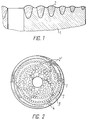
- the friction element of a friction pair contains a die 1, the surface of which is reinforced with a coating in the form of a large number of particles 2 with a developed surface (FIGS. 1, 2, 7, 9, 12-15).
- the particles 2 are made of a wear-resistant material, for example steel, which has a high hardness, heat and corrosion resistance compared to the material of the die 1, which has a lower hardness and density, a higher specific thermal conductivity and elasticity and, for example, one heat-resistant aluminum alloy.
- the particles 2 are fastened in the body of the die 1 and stand over their surface, forming their geometric shape according to various contours 2 ′ of a regular microrelief (FIGS. 2, 9, 12, 13, 14) , 15).
- the contours 2 ' are formed by the particles 2 with a non-equidistant distance between them in such a way that they form a variable surface area of the friction surface which decreases from the zone of maximum stress on the friction element to the zone of minimal stress on the same.
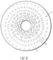
- variable surface area of the friction surface of the particles 2 can be generated both by changing their arrangement density (FIG. 2) and by changing their dimensions (FIG. 9).
- the particles 2 are practically on one of the concentric circular lines, the center of which coincides with the pivot point of the friction element.
- the particle 2 made of wear-resistant material can be made of at least two materials that form a composite material (FIG. 4).
- the particles lying in the zone of the maximum stresses of the die 1 are made from a more wear-resistant material than those in the zone of the minimum stresses, for example from different types of steel.
- the die 1 is made of a material with higher physical-mechanical characteristics in the zone of the maximum stresses than in the zone of the minimum stresses, for example each made of a copper and an aluminum alloy (FIG. 7).
- the material can be attached to the opposite disc surfaces with different levels of wear resistance.
- the total area of the particles 2 is prescribed by the conditions for ensuring a non-continuous coating and makes up up to 80% of the area of the total friction area.
- the particles 2 made of wear-resistant material are the particles 3 made of corrosion protection material (Fig. 2, 6).
- a design variant is also conceivable in which the corrosion-resistant layer is applied to the entire surface of the die 1 (FIG. 7).
- the material intended for the protective protection of the die 1 must be selected from a number of elements which are less galvanically resistant than the material of the die 1.
- the friction element in which there are particles 4 made of an abrasive material, for example Al2O3 (FIGS. 2, 5), between the particles 2, 3 made of wear-resistant material and corrosion protection material, which are compatible with the material of the die 1 metallized with copper, for example can be.
- an abrasive material for example Al2O3 (FIGS. 2, 5)
- the particles 3 lie chaotically in the die 1, whereas the particles 4 are expediently arranged along the contours 2 'of the existing microrelief (FIG. 2).
- the particles 2 made of wear-resistant material have an elliptical shape in the cross section parallel to the friction surface of the die 1 of the friction element (FIG. 11).
- a particle 2 is from 0.001 to 3.00 mm, but the larger 2a does not make more than two smaller axes "2b", the maximum dimension of a particle 2 in the normal at least the length of the smaller axis 2b of the ellipse (FIG. 10) must be the same, while the part of the particle 2 lying in the die 1 must not be less than half the height H thereof and must have a hyperbolic shape.
- the dimensions of the particles 2 are practically chosen on the basis of the condition of ensuring the correspondence with the spot of the actual contact.
- the maximum height H of the wear-resistant particle 2 is greater than the amount h (FIG. 10), with the aim that the point M (at which the shear stresses have their maximum value) lies in the material of the reinforcing particle 2, so that the maximum stresses be taken up by the reinforcing wear-resistant particles 2.
- the particles 2 with the larger ellipse axis 2a are oriented in the direction which practically corresponds to the direction of the relative displacement of the friction element, while they are in the zone of maximum temperature stresses are practically transverse to this direction (Fig. 9, 12, 14, 15).
- the particles 3, 4 are designed in the cross section parallel to the friction surface in the form of a circle with dimensions from 0.001 to 0.15 mm, while their dimensions in the normal to the friction surface are from 0.001 mm to 0.375 mm.
- the particles 2, 3, 4 form a wavy profile of uneven thickness on the friction surface.
- the tips of the particles 2 are subjected to an additional processing.
- the particles 3, 4 must have a protruding part which is smaller in size than the equilibrium roughness.
- the matrix 1 is reinforced by any known method, for example by spark doping or plasma spraying.
- the particles 2 made of wear-resistant material and the particles 4 made of abrasive material are expediently applied to the die 1 in the form of turns of a spiral, the slope of which in the direction of the increasing half diameter of the same increases in the opposite direction of formation.
- the spiral can be formed both continuously and interrupted (Fig. 2, 9, 12, 15).
- the particles 2, 4 When using the friction element as a friction pairing for a brake drum, the particles 2, 4 must be attached to the die 1 in the form of turns lying along a helical line.
- the contours 2 of the microrelief formed can be formed in such a way that the particles 2, 4 are grouped into at least one closed contours 5 (FIG. 12) in at least one of them to hold the wear products.
- the contact surface of the second element interacting with the particles 2, 3, 4 has the possibility of being completely covered by the latter due to the non-equidistant position thereof along the microrelief contours.
- the particles 2 made of wear-resistant material are distributed on the surface of the die 1 with different densities and / or with different dimensions according to the acting loads (FIGS. 7, 8), there is a possibility for the contact surface, the mentioned loads to oppose a differentiated resistance and thus to ensure uniform wear of the friction element.
- the particle 2 made of a more wear-resistant material in the zone of maximum mechanical stresses than in the zone of maximum temperature stresses and by the arrangement of the same with the larger ellipse axis 2a in the direction that practically corresponds to the Direction of the relative displacement of the friction element in the zone of maximum mechanical stresses coincides and runs transversely to this direction in the zone of minimum stresses.
- the particles 3 contribute to the protective protection of the product, whereas the particles 4 dress the surface contacting the surface of the friction element according to the invention.
- the constructive design of the friction element according to the invention guarantees a possibility of controlling its operating data, which extends the life of the product.
- the invention can be used in friction elements, the surface of which is said to have increased wear resistance, in particular in braking devices of passenger cars, in brake disks and drums, clutch disks, support structures, for example in track bearings, bearing sleeves and the like. as well as in die equipment and cutting tools.
Landscapes
- Engineering & Computer Science (AREA)
- General Engineering & Computer Science (AREA)
- Mechanical Engineering (AREA)
- Nitrogen And Oxygen Or Sulfur-Condensed Heterocyclic Ring Systems (AREA)
- Braking Arrangements (AREA)
Abstract
Un élément de friction destiné à une paire d'éléments de friction comprend une matrice (1) dont la surface de frottement est renforcée par un revêtement composé d'une pluralité de particules (2) doté d'une surface développée en matériau résistant à l'usure. Les particules (2) fixées dans le corps de la matrice dépassent de sa surface de manière à former un micro-relief (2'), et elles sont situées sur au moins une des circonférences coaxiales dont le centre est coïncidant avec le centre de rotation de l'élément de friction. Le micro-relief est formé par des particules (2) de manière à produire une aire variable de la surface de frottement, laquelle décroît dans le sens allant de la zone de contrainte maximum de l'élément à celle de sa contrainte minimum. Entre les particules du matériau résistant à l'usure se trouvent des particules (3, 4) d'un matériau résistant à la corrosion et d'un matériau abrasif. On obtient le renforcement par n'importe quel procédé connu, par exemple par alliage par électro-étincelles ou pulvérisation de plasma. On peut utiliser l'invention, par exemple, dans le disque de frein ou le tambour de frein d'un véhicule léger, ainsi que dans le disque d'embrayage.
Applications Claiming Priority (2)
| Application Number | Priority Date | Filing Date | Title |
|---|---|---|---|
| SU4804539 | 1990-03-19 | ||
| SU4804539 | 1990-03-19 |
Publications (2)
| Publication Number | Publication Date |
|---|---|
| EP0486693A1 true EP0486693A1 (fr) | 1992-05-27 |
| EP0486693A4 EP0486693A4 (en) | 1992-10-07 |
Family
ID=21503058
Family Applications (1)
| Application Number | Title | Priority Date | Filing Date |
|---|---|---|---|
| EP19910907230 Withdrawn EP0486693A4 (en) | 1990-03-19 | 1990-09-25 | Friction element for friction pair |
Country Status (3)
| Country | Link |
|---|---|
| EP (1) | EP0486693A4 (fr) |
| HU (1) | HUT60368A (fr) |
| WO (1) | WO1991014881A1 (fr) |
Cited By (11)
| Publication number | Priority date | Publication date | Assignee | Title |
|---|---|---|---|---|
| GB2287451B (en) * | 1994-03-16 | 1998-03-04 | Hitachi Ltd | Emergency stop apparatus for elevator |
| WO2003058089A1 (fr) * | 2002-01-14 | 2003-07-17 | Federal-Mogul Friction Products Gmbh | Garniture de friction et son procede de fabrication |
| CN102352901A (zh) * | 2011-10-04 | 2012-02-15 | 吉林大学 | 一种仿生耦合轨道车辆制动盘 |
| CN103111793A (zh) * | 2013-02-27 | 2013-05-22 | 吉林大学 | 在壁厚部件表面制备大深度仿生异质体的方法 |
| US20150027827A1 (en) * | 2013-07-24 | 2015-01-29 | David Rogers Campbell | Control of clamp mechanism by means of a variable thickness disc |
| US9458894B2 (en) * | 2014-04-29 | 2016-10-04 | National Coating Corporation | Friction material having customizable working surface and method of forming the same |
| CN106838076A (zh) * | 2016-12-13 | 2017-06-13 | 杭州电子科技大学 | 一种具有耐磨羟基磷灰石涂层的制动盘及制造方法 |
| CN108386465A (zh) * | 2018-05-07 | 2018-08-10 | 安徽工业大学 | 一种具有仿生表面的汽车制动盘 |
| DE102018116192A1 (de) * | 2018-07-04 | 2020-01-09 | Westfalia-Automotive Gmbh | Zugfahrzeugkupplung-Sensorvorrichtung mit reibschlüssigem Mitnehmer |
| CN111271396A (zh) * | 2020-01-17 | 2020-06-12 | 济南大学 | 一种表面具有熔覆凸块的刹车盘及其制备方法 |
| CN111386405A (zh) * | 2017-12-18 | 2020-07-07 | 舍弗勒技术股份两合公司 | 摩擦部件 |
Families Citing this family (1)
| Publication number | Priority date | Publication date | Assignee | Title |
|---|---|---|---|---|
| WO2018229995A1 (fr) * | 2017-06-16 | 2018-12-20 | 三菱電機株式会社 | Garniture de frein |
Family Cites Families (4)
| Publication number | Priority date | Publication date | Assignee | Title |
|---|---|---|---|---|
| US3899050A (en) * | 1971-07-06 | 1975-08-12 | Textar Gmbh | Lining for brake shoes |
| SU626282A1 (ru) * | 1977-03-01 | 1978-09-30 | Специализированное Конструкторское Бюро По Специальным Гусеничным Тракторам Класса 2 Тонны Тяги | Тормозна лента |
| JPS6035930U (ja) * | 1983-08-20 | 1985-03-12 | トキコ株式会社 | デイスクブレ−キ用摩擦パツド |
| US4639392A (en) * | 1985-10-28 | 1987-01-27 | General Motors Corporation | Clutch plate member having layer of high durability, self-conforming friction facing |
-
1990
- 1990-09-25 EP EP19910907230 patent/EP0486693A4/de not_active Withdrawn
- 1990-09-25 HU HU913982A patent/HUT60368A/hu unknown
- 1990-09-25 WO PCT/SU1990/000225 patent/WO1991014881A1/fr not_active Ceased
Cited By (16)
| Publication number | Priority date | Publication date | Assignee | Title |
|---|---|---|---|---|
| GB2287451B (en) * | 1994-03-16 | 1998-03-04 | Hitachi Ltd | Emergency stop apparatus for elevator |
| WO2003058089A1 (fr) * | 2002-01-14 | 2003-07-17 | Federal-Mogul Friction Products Gmbh | Garniture de friction et son procede de fabrication |
| CN102352901A (zh) * | 2011-10-04 | 2012-02-15 | 吉林大学 | 一种仿生耦合轨道车辆制动盘 |
| CN103111793A (zh) * | 2013-02-27 | 2013-05-22 | 吉林大学 | 在壁厚部件表面制备大深度仿生异质体的方法 |
| US20150027827A1 (en) * | 2013-07-24 | 2015-01-29 | David Rogers Campbell | Control of clamp mechanism by means of a variable thickness disc |
| US10427186B2 (en) | 2014-04-29 | 2019-10-01 | National Coating Corporation | Friction material and method of forming the same |
| US9458894B2 (en) * | 2014-04-29 | 2016-10-04 | National Coating Corporation | Friction material having customizable working surface and method of forming the same |
| CN106838076A (zh) * | 2016-12-13 | 2017-06-13 | 杭州电子科技大学 | 一种具有耐磨羟基磷灰石涂层的制动盘及制造方法 |
| CN111386405A (zh) * | 2017-12-18 | 2020-07-07 | 舍弗勒技术股份两合公司 | 摩擦部件 |
| US11187280B2 (en) | 2017-12-18 | 2021-11-30 | Schaeffler Technologies AG & Co. KG | Friction part |
| CN111386405B (zh) * | 2017-12-18 | 2021-12-07 | 舍弗勒技术股份两合公司 | 摩擦部件 |
| CN108386465A (zh) * | 2018-05-07 | 2018-08-10 | 安徽工业大学 | 一种具有仿生表面的汽车制动盘 |
| DE102018116192A1 (de) * | 2018-07-04 | 2020-01-09 | Westfalia-Automotive Gmbh | Zugfahrzeugkupplung-Sensorvorrichtung mit reibschlüssigem Mitnehmer |
| US11530004B2 (en) | 2018-07-04 | 2022-12-20 | Westfalia-Automotive Gmbh | Towing vehicle coupling sensor apparatus having friction-type follower |
| CN111271396A (zh) * | 2020-01-17 | 2020-06-12 | 济南大学 | 一种表面具有熔覆凸块的刹车盘及其制备方法 |
| CN111271396B (zh) * | 2020-01-17 | 2021-06-01 | 济南大学 | 一种表面具有熔覆凸块的刹车盘及其制备方法 |
Also Published As
| Publication number | Publication date |
|---|---|
| WO1991014881A1 (fr) | 1991-10-03 |
| EP0486693A4 (en) | 1992-10-07 |
| HU913982D0 (en) | 1992-07-28 |
| HUT60368A (en) | 1992-08-28 |
Similar Documents
| Publication | Publication Date | Title |
|---|---|---|
| EP0057808B1 (fr) | Coussinet de grand puissance | |
| EP0419684A1 (fr) | Element de frottement dans un couple de frottement | |
| EP0104159B1 (fr) | Palier à glissement hydrodynamique | |
| EP0318687B1 (fr) | Utilisation d'un type de fonte pour corps de frein ainsi que pour disques de frein à anneaux de frein et comportant, située dans le plan du frein, une partie ondulée entre anneau de frein et pot | |
| DE60201263T2 (de) | Reibbelag | |
| DE3430599C2 (de) | Verfahren zur Herstellung eines Bremsbelages für eine Scheibenbremse | |
| EP0486693A1 (fr) | Element de friction pour ensemble a friction | |
| DE3915898A1 (de) | Bohrspitze | |
| DE2952117B1 (de) | Kolbenbolzen | |
| EP1859178A1 (fr) | Disque de frein notamment destine a un vehicule | |
| DE19842455C2 (de) | Wälzlager | |
| DE3905450C2 (de) | Gleitlager | |
| DE102006009565A1 (de) | Bremsscheibe , insbesondere für ein Fahrzeug | |
| DE19721647C2 (de) | Reibeinheit in Massivbauweise, insbesondere Bremsscheibe, mit mehreren Reibkörpern | |
| DE102006054831A1 (de) | Struktur für ein dreibeiniges Kreuzgelenk und ein Verfahren zur Montage einer Rollenanordnung | |
| DE3917782C2 (de) | Bremsbelag zur Verwendung bei einer Scheibenbremse | |
| DE2819306C2 (fr) | ||
| DE60203296T2 (de) | Kontaktlager | |
| AT409531B (de) | Gleitlager für eine verbrennungskraftmaschine | |
| DE102022109988B4 (de) | Verschleissfestes armiertes schneidwerkzeug sowie verfahren zur herstellung | |
| WO2000040850A1 (fr) | Moteur a piston alternatif | |
| DE60224176T3 (de) | Scheibenbremse für einen schwerlastkraftwagen und ein solch eine scheibenbremse enthaltendes fahrzeug | |
| DE102019216199A1 (de) | Werkzeugteil und Verfahren zum Herstellen eines solchen Werkzeugteils | |
| DE60122726T2 (de) | Bremselement, scheibenbremse, trommelbremse | |
| DE10308130A1 (de) | Gewindeprofil |
Legal Events
| Date | Code | Title | Description |
|---|---|---|---|
| PUAI | Public reference made under article 153(3) epc to a published international application that has entered the european phase |
Free format text: ORIGINAL CODE: 0009012 |
|
| 17P | Request for examination filed |
Effective date: 19911218 |
|
| AK | Designated contracting states |
Kind code of ref document: A1 Designated state(s): BE DE FR GB IT SE |
|
| A4 | Supplementary search report drawn up and despatched | ||
| AK | Designated contracting states |
Kind code of ref document: A4 Designated state(s): BE DE FR GB IT SE |
|
| STAA | Information on the status of an ep patent application or granted ep patent |
Free format text: STATUS: THE APPLICATION IS DEEMED TO BE WITHDRAWN |
|
| 18D | Application deemed to be withdrawn |
Effective date: 19940401 |