EP0486722A1 - Serrure cylindrique - Google Patents
Serrure cylindrique Download PDFInfo
- Publication number
- EP0486722A1 EP0486722A1 EP90122319A EP90122319A EP0486722A1 EP 0486722 A1 EP0486722 A1 EP 0486722A1 EP 90122319 A EP90122319 A EP 90122319A EP 90122319 A EP90122319 A EP 90122319A EP 0486722 A1 EP0486722 A1 EP 0486722A1
- Authority
- EP
- European Patent Office
- Prior art keywords
- cylinder
- sections
- lock according
- cylinder lock
- key
- Prior art date
- Legal status (The legal status is an assumption and is not a legal conclusion. Google has not performed a legal analysis and makes no representation as to the accuracy of the status listed.)
- Withdrawn
Links
- 239000000853 adhesive Substances 0.000 claims abstract 2
- 230000001070 adhesive effect Effects 0.000 claims abstract 2
- 230000037431 insertion Effects 0.000 claims abstract 2
- 238000003780 insertion Methods 0.000 claims abstract 2
- 238000000926 separation method Methods 0.000 abstract description 2
- 230000000903 blocking effect Effects 0.000 abstract 1
- 238000000576 coating method Methods 0.000 description 4
- 239000011248 coating agent Substances 0.000 description 3
- 230000008878 coupling Effects 0.000 description 3
- 238000010168 coupling process Methods 0.000 description 3
- 238000005859 coupling reaction Methods 0.000 description 3
- 239000002184 metal Substances 0.000 description 2
- 239000004809 Teflon Substances 0.000 description 1
- 229920006362 Teflon® Polymers 0.000 description 1
- 230000005540 biological transmission Effects 0.000 description 1
- 238000011109 contamination Methods 0.000 description 1
- 230000000694 effects Effects 0.000 description 1
- 238000009434 installation Methods 0.000 description 1
- 238000007493 shaping process Methods 0.000 description 1
Images

Classifications
-
- E—FIXED CONSTRUCTIONS
- E05—LOCKS; KEYS; WINDOW OR DOOR FITTINGS; SAFES
- E05B—LOCKS; ACCESSORIES THEREFOR; HANDCUFFS
- E05B27/00—Cylinder locks or other locks with tumbler pins or balls that are set by pushing the key in
- E05B27/0003—Details
- E05B27/0007—Rotors
- E05B27/001—Rotors having relatively movable parts, e.g. coaxial- or split-plugs
-
- E—FIXED CONSTRUCTIONS
- E05—LOCKS; KEYS; WINDOW OR DOOR FITTINGS; SAFES
- E05B—LOCKS; ACCESSORIES THEREFOR; HANDCUFFS
- E05B27/00—Cylinder locks or other locks with tumbler pins or balls that are set by pushing the key in
- E05B27/0057—Cylinder locks or other locks with tumbler pins or balls that are set by pushing the key in with increased picking resistance
- E05B27/0075—Cylinder locks or other locks with tumbler pins or balls that are set by pushing the key in with increased picking resistance by movable rotor elements
-
- E—FIXED CONSTRUCTIONS
- E05—LOCKS; KEYS; WINDOW OR DOOR FITTINGS; SAFES
- E05B—LOCKS; ACCESSORIES THEREFOR; HANDCUFFS
- E05B45/00—Alarm locks
- E05B45/06—Electric alarm locks
Definitions
- the invention relates to a cylinder lock with at least one lock cylinder which is rotatably mounted in a housing and through which a key channel for inserting a key extends, the lock cylinder being subdivided into at least two separate cylinder sections which are mounted coaxially in the common housing.
- a lock is known from CH-PS No. 667 305.
- the locking principle of cylinder locks is based on the fact that a large number of locking pins are provided, which usually consist of a spring-loaded housing pin in the lock housing and a corresponding core pin in the cylinder.
- the locking pins can be aligned in their longitudinal direction so that the separation points between all housing pins and core pins lie on the cylinder jacket, so that the cylinder can be rotated, taking the core pins with it.
- the locking beard coupled to the cylinder via a coupling member is also carried along by the cylinder and actuates a bolt or the like.
- the cylinder and thus the locking beard can usually only be turned when all locking pins are correctly aligned with the appropriate key. Since it can be possible under certain conditions to align the locking pins without inserting a key into the key channel, by acting on the cylinder to influence all locking pins in the direction of rotation from the outside, it was proposed in the aforementioned CH-PS 667 305 to split the cylinder into several cylinder sections to divide.
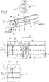
- FIG. 1 the elements of the invention are shown with the aid of a double cylinder lock, the housing 15, in which one cylinder 1, 1 'and 2 each is stored, is only indicated in Figure 2.
- the locking pins are only shown by holes 10 in the cylinders.
- the two cylinders 1, 1 'and 2 can be actuated independently of one another.
- the respectively actuated cylinder acts on a locking beard 3 via a two-winged coupling member 5, which is arranged displaceably in longitudinal slots 12 at the inner cylinder ends.
- the two wings 8, 9 are rotatably fastened to one another.
- This coupling member 5 assumes a position by the action of the key, in which it couples the corresponding cylinder with the locking beard 3 by engaging in a slot 14 in the locking beard, and uncouples the other cylinder from the locking beard.
- the locking beard 3 in turn acts via a cam 4 on the bolt (not shown).
- the division of the locking cylinder according to the invention is realized in this exemplary embodiment only on the outer cylinder 1, 1 ', against which the manipulations mentioned can be directed.
- a corresponding design of both cylinders of a double cylinder lock is possible in the same way, so that the installation direction remains free.
- the single cylinder of a single cylinder lock can also be designed in this way.
- the outer cylinder thus has two separate cylinder sections 1 and 1 ', which are mounted in the common housing 15, both of which are provided with locking pins, indicated by the bores 10. Only the cylinder section 1 is visible and accessible from the outside.
- the inner cylinder section 1 ' should only be able to be subjected to rotation if a suitable instrument - in particular a key - is inserted in the key channel 11 through the outer cylinder section 1 to the inner section 1' becomes. However, this alters the alignment of the locking pins in the outer cylinder section 1, if the appropriate key is not used.
- the two cylinder sections 1 and 1 ' are mounted in the housing 15 without play.
- a securing spring 6 which can be inserted into the housing 15 is provided on at least one, preferably the inner section 1 'for axially holding the cylinder sections 1 and 1'.
- the outer section 1 is then held in the rest position of the cylinder by the locking pins and, when the cylinder is rotated, by the key axially fixed in the inner section 1 '.
- the outer cylinder section 1 can also be held axially by means of a locking spring 17 (FIG. 5).
- the end face of the outer cylinder section 1 is beveled conically starting from the key channel 11 (see FIGS. 1 to 3), so that the contact area between the two cylinder sections is essentially limited to the key channel.
- the key channel 11 remains essentially without a gap, with which the key can still be inserted easily, and the axial play of the cylinder sections is practical is canceled. This property also represents a further security feature in that it makes manipulation through interventions between the two cylinder sections impossible.
- the said bevel can also be replaced by a recess of a different shape and only needs to be relatively small. Fractions of a millimeter are sufficient for this, so that as little space as possible is used for the locking pins 10 (cf. FIG. 3).
- a corresponding design of the end face can also be present on the other or on both cylinder sections.
- the friction can also be reduced by applying appropriate, wear-resistant non-stick coatings.
- FIGS. 4 and 5 Corresponding designs are shown in FIGS. 4 and 5, only one end face in FIG. 4 being provided with a granular metal coating 21 which prevents the cylinder sections from sticking together flatly.
- both end faces are provided with a Teflon coating 22 or 22 ', an embodiment of the invention being shown here, in which the outer cylinder section 1 has no locking pins, but is freely rotatable in front of the inner section 1' provided with the locking pins . So that the key channel 11 of the two sections 1, 1 'remains aligned, the outer cylinder section 1 can be held in the rest position by means of a latching device.
- the cylinder lock can be provided with an additional securing device, which is arranged between the cylinder sections 1, 1 'and which responds to any relative rotation of the two cylinder sections, which can be used to trigger an alarm.
- an additional securing device is shown schematically in FIG. 6 in combination with the embodiment of FIG.
- a contact pin 23 is arranged in the rear cylinder section 1 'and is slightly biased against the end face of the front cylinder section 1.
- This is e.g. an insulating coating is interrupted in places, in such a way that the contact pin touches the metal body of the front cylinder section 1 when the two cylinder sections are rotated relative to one another and thus closes a contact circuit (not shown) between the cylinder sections.
- This could also be designed as a circuit. Corresponding manipulation of the cylinder can be detected and an alarm can be given.
- this security device can be used not only in combination with the features according to the invention, but also in a lock according to CH-PS 667 305 mentioned at the beginning.
Landscapes
- Lock And Its Accessories (AREA)
Priority Applications (1)
| Application Number | Priority Date | Filing Date | Title |
|---|---|---|---|
| EP90122319A EP0486722A1 (fr) | 1990-11-22 | 1990-11-22 | Serrure cylindrique |
Applications Claiming Priority (1)
| Application Number | Priority Date | Filing Date | Title |
|---|---|---|---|
| EP90122319A EP0486722A1 (fr) | 1990-11-22 | 1990-11-22 | Serrure cylindrique |
Publications (1)
| Publication Number | Publication Date |
|---|---|
| EP0486722A1 true EP0486722A1 (fr) | 1992-05-27 |
Family
ID=8204741
Family Applications (1)
| Application Number | Title | Priority Date | Filing Date |
|---|---|---|---|
| EP90122319A Withdrawn EP0486722A1 (fr) | 1990-11-22 | 1990-11-22 | Serrure cylindrique |
Country Status (1)
| Country | Link |
|---|---|
| EP (1) | EP0486722A1 (fr) |
Cited By (3)
| Publication number | Priority date | Publication date | Assignee | Title |
|---|---|---|---|---|
| DE19700333A1 (de) * | 1997-01-08 | 1998-07-09 | Danijel Golub | Umstellbares Zylinderschloß auf Standard oder Not- und Gefahrenfunktion mit Zutrittsberechtigungsfreigabe ohne Ausbau und durch unterschiedlich gebildete Schlüssel auf die Kupplungsmechanik wirkend bestimmbar |
| EP2982817A4 (fr) * | 2013-04-03 | 2016-11-16 | Li-Szu Shen | Barillet de serrure |
| CN108222697A (zh) * | 2018-01-30 | 2018-06-29 | 东风商用车有限公司 | 一种尿素罐锁盖 |
Citations (4)
| Publication number | Priority date | Publication date | Assignee | Title |
|---|---|---|---|---|
| US1755847A (en) * | 1925-03-25 | 1930-04-22 | Phillip W Gross | Lock |
| US3808854A (en) * | 1972-12-13 | 1974-05-07 | L Mercurio | Pilfer-resistant lock construction, having segmented cylinder |
| WO1985000399A1 (fr) * | 1983-07-05 | 1985-01-31 | Eric Joseph Manche | Serrure a cylindre segmente |
| CH667305A5 (en) * | 1985-08-23 | 1988-09-30 | Bernhard Faude | Lock with cylinder in several sections - can be opened by rotating outer section of cylinder only when key is inserted |
-
1990
- 1990-11-22 EP EP90122319A patent/EP0486722A1/fr not_active Withdrawn
Patent Citations (4)
| Publication number | Priority date | Publication date | Assignee | Title |
|---|---|---|---|---|
| US1755847A (en) * | 1925-03-25 | 1930-04-22 | Phillip W Gross | Lock |
| US3808854A (en) * | 1972-12-13 | 1974-05-07 | L Mercurio | Pilfer-resistant lock construction, having segmented cylinder |
| WO1985000399A1 (fr) * | 1983-07-05 | 1985-01-31 | Eric Joseph Manche | Serrure a cylindre segmente |
| CH667305A5 (en) * | 1985-08-23 | 1988-09-30 | Bernhard Faude | Lock with cylinder in several sections - can be opened by rotating outer section of cylinder only when key is inserted |
Cited By (3)
| Publication number | Priority date | Publication date | Assignee | Title |
|---|---|---|---|---|
| DE19700333A1 (de) * | 1997-01-08 | 1998-07-09 | Danijel Golub | Umstellbares Zylinderschloß auf Standard oder Not- und Gefahrenfunktion mit Zutrittsberechtigungsfreigabe ohne Ausbau und durch unterschiedlich gebildete Schlüssel auf die Kupplungsmechanik wirkend bestimmbar |
| EP2982817A4 (fr) * | 2013-04-03 | 2016-11-16 | Li-Szu Shen | Barillet de serrure |
| CN108222697A (zh) * | 2018-01-30 | 2018-06-29 | 东风商用车有限公司 | 一种尿素罐锁盖 |
Similar Documents
| Publication | Publication Date | Title |
|---|---|---|
| AT392818B (de) | Schliesssystem | |
| DE69424026T2 (de) | Zylinderschloss | |
| DE10084766T5 (de) | Vorrichtung zum Zusammenfügen Zweier Teile, welche eine Positionsspiel Aufweisen | |
| DE3838481A1 (de) | Zylinderschloss | |
| DE2942789A1 (de) | Permutationsschloss | |
| EP0364660A2 (fr) | Serrure cylindrique | |
| DE69916122T2 (de) | Zylinderschloss | |
| DE4343024C2 (de) | Vorrichtung zur veränderbaren Kodierung und diese enthaltende Verbindungsvorrichtung | |
| DE69318478T2 (de) | Verfahren zum Verbinden eines ersten Endes eines Kabels an einer Antriebseinheit und Vorrichtung, Antriebseinheit und Kabel zur Ausführung des Verfahrens | |
| EP0486722A1 (fr) | Serrure cylindrique | |
| EP0574752B1 (fr) | Clé et cylindre de serrure correspondant notamment cyclindre de serrure profilé | |
| EP0632176A1 (fr) | Cylindre de fermeture | |
| EP0625624A1 (fr) | Serrure cylindrique | |
| DE3619048A1 (de) | Verbindungseinrichtung | |
| CH674542A5 (en) | Security lock cylinder - has core with rear end flange inserted from rear and front covering head | |
| DE3506554C2 (fr) | ||
| DE7929218U1 (de) | Zylinderschloss mit flachschluessel | |
| EP0330803B1 (fr) | Cylindre pour serrure de sécurité | |
| EP0715766A1 (fr) | Interrupteur de securite | |
| DE9307547U1 (de) | Schließzylinder | |
| DE3226607A1 (de) | Einbau-doppel-profil-zylinderschloss mit zylinderkern und mit diesem fest verbundenem mitnehmer | |
| DE868122C (de) | Fallenschloss mit Sperreinrichtung | |
| CH334964A (de) | Einbaudoppelzylinder für Einsteckschlösser mit Schlüssel- und Handgriffbetätigung | |
| DE3614881A1 (de) | Scharnier mit arretierung | |
| DE3904333A1 (de) | Aus doppelschliesszylinder und schluesseln bestehende schliessvorrichtung |
Legal Events
| Date | Code | Title | Description |
|---|---|---|---|
| PUAI | Public reference made under article 153(3) epc to a published international application that has entered the european phase |
Free format text: ORIGINAL CODE: 0009012 |
|
| AK | Designated contracting states |
Kind code of ref document: A1 Designated state(s): AT BE CH DE DK ES FR GB GR IT LI LU NL SE |
|
| RBV | Designated contracting states (corrected) |
Designated state(s): AT BE CH DE FR GB IT LI NL SE |
|
| 17P | Request for examination filed |
Effective date: 19921116 |
|
| 17Q | First examination report despatched |
Effective date: 19930827 |
|
| STAA | Information on the status of an ep patent application or granted ep patent |
Free format text: STATUS: THE APPLICATION IS DEEMED TO BE WITHDRAWN |
|
| 18D | Application deemed to be withdrawn |
Effective date: 19940107 |