EP0486740B1 - Machine de thermoformage de matières plastiques - Google Patents
Machine de thermoformage de matières plastiques Download PDFInfo
- Publication number
- EP0486740B1 EP0486740B1 EP19900403273 EP90403273A EP0486740B1 EP 0486740 B1 EP0486740 B1 EP 0486740B1 EP 19900403273 EP19900403273 EP 19900403273 EP 90403273 A EP90403273 A EP 90403273A EP 0486740 B1 EP0486740 B1 EP 0486740B1
- Authority
- EP
- European Patent Office
- Prior art keywords
- machine
- sheet
- turntable
- piston
- matrix
- Prior art date
- Legal status (The legal status is an assumption and is not a legal conclusion. Google has not performed a legal analysis and makes no representation as to the accuracy of the status listed.)
- Expired - Lifetime
Links
- 238000003856 thermoforming Methods 0.000 title claims description 14
- 239000004033 plastic Substances 0.000 title claims description 11
- 229920003023 plastic Polymers 0.000 title claims description 11
- 239000000463 material Substances 0.000 title claims description 8
- 239000011159 matrix material Substances 0.000 claims description 12
- 229920001169 thermoplastic Polymers 0.000 claims description 6
- 239000004416 thermosoftening plastic Substances 0.000 claims description 6
- 238000010438 heat treatment Methods 0.000 claims description 2
- 238000003780 insertion Methods 0.000 claims description 2
- 230000037431 insertion Effects 0.000 claims description 2
- 238000003825 pressing Methods 0.000 claims description 2
- 238000006073 displacement reaction Methods 0.000 claims 1
- 238000007664 blowing Methods 0.000 description 3
- 238000000034 method Methods 0.000 description 3
- 230000009471 action Effects 0.000 description 2
- 230000015572 biosynthetic process Effects 0.000 description 2
- 239000002131 composite material Substances 0.000 description 2
- 238000004519 manufacturing process Methods 0.000 description 2
- 238000004806 packaging method and process Methods 0.000 description 2
- 239000002985 plastic film Substances 0.000 description 2
- 238000011084 recovery Methods 0.000 description 2
- 239000004743 Polypropylene Substances 0.000 description 1
- 239000004793 Polystyrene Substances 0.000 description 1
- 238000005520 cutting process Methods 0.000 description 1
- 238000001125 extrusion Methods 0.000 description 1
- 230000005484 gravity Effects 0.000 description 1
- 238000002347 injection Methods 0.000 description 1
- 239000007924 injection Substances 0.000 description 1
- 239000007788 liquid Substances 0.000 description 1
- 230000007246 mechanism Effects 0.000 description 1
- 230000008520 organization Effects 0.000 description 1
- 239000000123 paper Substances 0.000 description 1
- 230000003071 parasitic effect Effects 0.000 description 1
- 230000000149 penetrating effect Effects 0.000 description 1
- 230000000704 physical effect Effects 0.000 description 1
- -1 polypropylene Polymers 0.000 description 1
- 229920001155 polypropylene Polymers 0.000 description 1
- 229920002223 polystyrene Polymers 0.000 description 1
- 229920000915 polyvinyl chloride Polymers 0.000 description 1
- 239000004800 polyvinyl chloride Substances 0.000 description 1
- 230000008569 process Effects 0.000 description 1
- 230000002787 reinforcement Effects 0.000 description 1
- 239000000523 sample Substances 0.000 description 1
Images

Classifications
-
- B—PERFORMING OPERATIONS; TRANSPORTING
- B29—WORKING OF PLASTICS; WORKING OF SUBSTANCES IN A PLASTIC STATE IN GENERAL
- B29C—SHAPING OR JOINING OF PLASTICS; SHAPING OF MATERIAL IN A PLASTIC STATE, NOT OTHERWISE PROVIDED FOR; AFTER-TREATMENT OF THE SHAPED PRODUCTS, e.g. REPAIRING
- B29C51/00—Shaping by thermoforming, i.e. shaping sheets or sheet like preforms after heating, e.g. shaping sheets in matched moulds or by deep-drawing; Apparatus therefor
- B29C51/18—Thermoforming apparatus
- B29C51/20—Thermoforming apparatus having movable moulds or mould parts
- B29C51/22—Thermoforming apparatus having movable moulds or mould parts rotatable about an axis
-
- B—PERFORMING OPERATIONS; TRANSPORTING
- B29—WORKING OF PLASTICS; WORKING OF SUBSTANCES IN A PLASTIC STATE IN GENERAL
- B29C—SHAPING OR JOINING OF PLASTICS; SHAPING OF MATERIAL IN A PLASTIC STATE, NOT OTHERWISE PROVIDED FOR; AFTER-TREATMENT OF THE SHAPED PRODUCTS, e.g. REPAIRING
- B29C51/00—Shaping by thermoforming, i.e. shaping sheets or sheet like preforms after heating, e.g. shaping sheets in matched moulds or by deep-drawing; Apparatus therefor
- B29C51/16—Lining or labelling
- B29C51/165—Lining or labelling combined with the feeding or the shaping of the lining or the labels
Definitions
- the present invention relates to a thermoforming machine for plastics intended in particular, but not exclusively, to allow the association of heterogeneous materials.
- FR-A-2 225 263 also describes a device for manufacturing objects by deep drawing comprising a horizontal rotary table rotating step by step and comprising several molds making it possible to form a plastic sheet in a cup inside the mold. But the cup is introduced already shaped in the mold.
- this method has drawbacks, in particular in that, once the container body has been thermoformed by known blowing, vacuum or piston processes, it is necessary to cut the upper part thereof to obtain a configuration contour exactly determined, in particular when the container has a flange at its upper part. This operation requires powerful presses. In addition, in thermoforming of composite packaging, offcuts from the cropping cannot be recycled as they are different materials. Finally, in conventional thermoforming there are parasitic phenomena related to the orientation of the sheet. Indeed, the formation of such a sheet leads to internal directional tensions which, combined with the force exerted for driving the sheet, produce random results.
- this machine is not suitable for forming inside a label.
- FR-A-2 308 484 on which the preamble of independent claim 1 is based describes a device for forming a thermoplastic sheet comprising a vertical plate, rotating step by step, before which the sheet is brought, the plate carrying the at least three hollow molds, blowing and / or suction means correspond with a station for introducing labels.
- the machine described does not allow pistoning under high pressure.
- the present invention relates to a thermoforming machine overcoming these drawbacks.
- the machine for thermoforming plastics comprising means for supplying and heating a thermoplastic sheet in front of a vertical plate rotating around a horizontal axis carrying at least one matrix, and means for applying the sheet.
- the turntable step by step in front of a plurality of work stations including a label insertion station, the tray comprising a center from which extend radial branches, each of the branches carrying at least one matrix is characterized in that the thermoplastic sheet is heated horizontally and after passing over a roller falls under its own weight between a forming piston, driven by a reciprocating movement, and the plate.
- the mold or matrix is carried by a kind of barrel which moves according to a determined angular pitch.
- the axis of rotation of the plate is perpendicular to the direction of movement of the sheet, a counter-piston animated by a horizontal reciprocating movement under the action of a jack being applied against the plate in synchronism with the movement of the piston.
- thermoformed products of remarkable quality even with very complex label shapes.
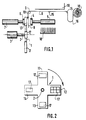
- the machine comprises, inside a frame (not shown), a plate 1 rotating around a horizontal axis 2 driven by a motor 3.
- the plate 1 comprises, in the example shown, four branches 11, 12, 13 and 14.
- the machine also comprises a piston 4 driven by a horizontal reciprocating movement by a hydraulic cylinder 5.
- a counter piston 6 Opposite the piston 4, there is a counter piston 6 also driven by a horizontal reciprocating movement under the action of a counter piston cylinder 7.
- the plastic band 8 is driven without tension by a roller 9 and it falls vertically between the piston 4 and the plate 1. It is advantageously unwound from a roller 10 and flows freely on guide rollers 15 after forming a recovery loop 16, the level of which is of course electronically controlled.
- the sheet 8 is gradually heated by elements 19, first horizontally and then vertically so that the sheet arrives at a temperature exactly determined opposite the forming station.
- various security means such as cells and thermal probes are arranged throughout the course of the sheet.
- this piston 4 advantageously carries a certain number of reliefs themselves constituting pistons to simultaneously form the greatest possible number of containers.
- Each of the branches 11 to 14 corresponds during a cycle to a particular operation.
- a label is introduced into the matrix 17 of the branch 11 by a device 18 (FIG. 1) conventional of the suction cup type for example.
- the previous label of the stack placed inside the matrix in the branch 12 is applied against the walls while at the same time, the thermoforming is carried out in the matrix 17 of the branch 13, and that the thermoformed container of branch 14 is evacuated to a packaging station.
- the operations and mechanisms for inserting the label and extracting the thermoformed container are common in the art considered and will not be described further. but the label introduced flat is conformed throughout the cycle to determine the volume in which the forming will take place.
- the operation of the machine in masked time saves time and achieves a production rate which can reach 20 to 25 strokes per minute.
- plate 1 rotates, in principle by a quarter of a turn each time. however, in the case of labels with a complicated configuration, the plate can rotate for example by an eighth of a turn, at each step so as to increase the number of work stations. It is thus possible, in the case of labels of complex shapes to solve the problems of axes.
- the device 18 grasps the label and conforms it inside the mold. But when the container to be formed is deep it can be useful in order to avoid sophisticated mechanization to introduce the labels successively on successive stations.
- FIG 3 shows in more detail the organization of the counter piston 6 which comprises a pressure plate 20 guided by two rods 21 sliding in bearings 22, the plate 23 is driven by the piston 7 (not shown in Figure 3).
- the machine according to the present invention also makes it possible to easily replace the tools (forms and dies) which are removably mounted respectively on the piston and on the plate 1. Taking into account the counter pressure exerted by the counter piston, it it is possible to work at high pressure and for example by applying pressures from 15 to 20 bars. And thus obtained by thermoforming parts of the same quality as those normally obtained by injection.
Landscapes
- Engineering & Computer Science (AREA)
- Mechanical Engineering (AREA)
- Blow-Moulding Or Thermoforming Of Plastics Or The Like (AREA)
Description
- La présente invention a pour objet une machine de thermoformage de matières plastiques destinée en particulier, mais non exclusivement, à permettre l'association de matériaux hétérogènes.
- L'idée d'utiliser des propriétés physiques des matières plastiques pour obtenir des récipients en déformant une bande ou feuille plastique préalablement ramollie par la chaleur par pression, ou par dépression est connue depuis très longtemps. Si la géométrie des produits obtenus par thermoformage dans un moule est satisfaisante, le problème de la décoration de la paroi latérale extérieure et éventuellement du fond reste difficile.
- Il a déjà été proposé par un EP-A- 83 107 545 de former des récipients composites dont la paroi externe est constituée par une feuille de carton décorée, cette feuille de carton étant tapissée intérieurement par une feuille de matière plastique appliquée par soufflage ou par emboutissage profond. Ainsi, l'enveloppe extérieure à base de papier de carton ou tout autre matériau approprié assure la rigidité dimensionnelle alors que la matière plastique très mince sert pour l'essentiel à assurer l'étanchéité du récipient au liquide. Les matières les plus couramment utilisées sont : le polystyrène, le chlorure de polyvinyle ou le polypropylène. Au cours de l'emboutissage, on obtient un collage à chaud entre la couche de carton et la couche de matière plastique. Bien entendu, la forme du manchon de carton correspond, au moins approximativement, à la forme extérieure du récipient que l'on désire obtenir. Mais, un tel procédé n'est appliquable que lorsque la forme du récipient est relativement simple.
- Les étiquettes lorsqu'elles sont introduites à plat dans la machine doivent subir, dans certains cas, différents pliages successifs pour être conformées selon un volume déterminé. Cette suite de pliages ne peut pas être effectuée dans la machine ci-dessus.
- FR-A-2 225 263 décrit également un dispositif de fabrication d'objets par emboutissage profond comprenant une table tournante horizontale tournant pas à pas et comportant plusieurs moules permettant de former une feuille plastique dans un gobelet intérieur au moule. Mais le gobelet est introduit déjà conformé dans le moule.
- De plus, ce procédé présente des inconvénients notamment en ce que, une fois que le corps du récipient a été thermoformé par des procédés de soufflage, de vide ou de pistonage connus, il faut en découper la partie supérieure pour obtenir un contour de configuration exactement déterminée, en particulier lorsque le récipient présente à sa partie supérieure une collerette. Cette opération nécessite des presses puissantes. Par ailleurs, dans le thermoformage des emballages composites, les chutes provenant des détourages ne sont pas recyclables dans la mesure où il s'agit de matériaux différents. Enfin, dans le thermoformage classique il existe des phénomènes parasites liés à l'orientation de la feuille. En effet, la formation d'une telle feuille conduit à des tensions internes directionnelles qui, conjuguées à la force exercée pour l'entraînement de la feuille, produisent des résultats aléatoires.
- Est connue par US-A-4 244 915 une machine de thermoformage de récipients en matière plastique, qui divulgue l'idée d'utiliser la pesanteur pour le déplacement d'une feuille thermoplastique molle. La feuille descendant verticalement à la sortie de l'extrudeuse est entraînée entre deux plateaux tournants ce qui nécessite un renforcement de l'épaisseur des bords et par suite des tensions nouvelles par rapport à celles qui résultent de l'extrusion.
- Mais cette machine n'est pas adaptée au formage à l'intérieur d'une étiquette.
- FR-A-2 308 484 sur lequel se base le préambule de la revendication indépendante 1, décrit un dispositif de formage d'une feuille thermoplastique comprenant un plateau vertical, tournant pas à pas, devant lequel est amenée la feuille, le plateau portant au moins trois moules en creux, des moyens de soufflage et/ou aspiration correspondent avec un poste d'introduction d'étiquettes. La machine décrite ne permet pas de réaliser un pistonnage sous haute pression.
- La présente invention a pour objet une machine de thermoformage palliant ces inconvénients.
- Selon la présente invention, la machine de thermoformage de matières plastiques comprenant des moyens d'amenée et de chauffage d'une feuille thermoplastique devant un plateau vertical tournant autour d'un axe horizontal portant au moins une matrice, et des moyens pour appliquer la feuille à l'intérieur de la matrice, le plateau tournant pas à pas devant une pluralité de postes de travail dont un poste d'introduction d'étiquettes, le plateau comprenant un centre à partir duquel s'étendent des branches radiales, chacune des branches portant au moins une matrice, est caractérisée en ce que la feuille thermoplastique est chauffée horizontalement et après passage sur un rouleau tombe sous son propre poids entre un piston de formage, animé d'un mouvement alternatif, et le plateau.
- Ainsi, il est possible d'introduire dans la matrice par exemple une étiquette, à plat et de la conformer avant que le thermoformage de la feuille plastique qui défile entre la matrice et le piston ne se produise. C'est-à-dire que le moule ou matrice est porté par une sorte de barillet qui se déplace selon un pas angulaire déterminé.
- Selon une autre caractéristique de l'invention, l'axe de rotation du plateau est perpendiculaire à la direction de déplacement de la feuille, une contre-piston animé d'un mouvement alternatif horizontal sous l'action d'un vérin étant appliqué contre le plateau en synchronisme avec le mouvement du piston.
- L'existence de branches radiales permet de diminuer l'inertie du plateau tournant et facilite l'introduction des différents composants. Par contre, l'inertie étant diminuée il est nécessaire d'équilibrer la pression du piston par la poussée d'un contre piston de manière à ce que, aucune force importante ne soit transmise sur l'axe de rotation, le contre piston appliqué sur la branche radiale avançant simultanément au mouvement d'avancée du piston. Ainsi, l'entraînement en rotation du plateau autour de son axe horizontal ne demande qu'une énergie réduite.
- La feuille préalablement chauffée descend devant le poste du thermoformage sous son propre poids après que toutes les tensions notamment dues à la formation de la feuille aient été relachées. On obtient ainsi, des produits thermoformés d'une qualité remarquable même avec des formes d'étiquettes très complexes.
- D'autres caractéristiques et avantages de l'invention apparaîtront au cours de la description qui va suivre d'un mode particulier de réalisation, donné uniquement à titre d'exemple non limitatif, en regard des dessins qui représentent :
- La figure 1, une vue schématique en élévation d'une machine selon l'invention ;
- La figure 2, une vue de face du plateau tournant ;
- La figure 3, une vue partielle par-dessus de la machine.
- Sur la figure 1, on voit que la machine comprend à l'intérieur d'un bâti (non représenté) un plateau 1 tournant autour d'un axe horizontal 2 entraîné par un moteur 3. Comme cela apparaît sur la figure 2, le plateau 1 comprend, dans l'exemple représenté, quatre branches 11, 12, 13 et 14. La machine comprend également un piston 4 animé d'un mouvement alternatif horizontal par un vérin hydraulique 5. En regard du piston 4, se trouve un contre piston 6 également animé d'un mouvement alternatif horizontal sous l'action d'un vérin de contre piston 7. La bande de matière plastique 8 est entraînée sans tension par un rouleau 9 et elle tombe verticalement entre le piston 4 et le plateau 1. Elle est avantageusement déroulée à partir d'un rouleau 10 et circule librement sur des rouleaux 15 de guidage après formation d'une boucle de récupération 16 dont le niveau est bien entendu contrôlé électroniquement. La feuille 8 est progressivement chauffée par des éléments 19, d'abord horizontalement puis verticalement de manière à ce que la feuille arrive à une température exactement déterminée en regard du poste de formage. Bien entendu, différents moyens de sécurité telles que des cellules et des sondes thermiques sont disposés tout au long du parcours de la feuille. Après découpe par le piston 4 et thermoformage le reste de la bande 8 est dirigé dans un bac de récupération (non représenté).
- Dans ce qui précède il a été question d'un piston 4. Mais bien entendu, ce piston 4 porte avantageusement un certain nombre de reliefs constituant eux-même des pistons pour former simultanément le plus grand nombre possible de récipients. On peut par exemple, avoir six formes pénétrant dans six matrices 17 telle que celle qui est schématiquement représentée sur la branche 12 du plateau 1 sur la figure 2. Chacune des branches 11 à 14 correspond au cours d'un cycle à une opération particulière. Par exemple, le plateau étant représenté dans la position qu'il occupe sur la figure 2, une étiquette est introduite dans la matrice 17 de la branche 11 par un dispositif 18 (figure 1) classique du type à ventouse par exemple. Pendant ce temps, l'étiquette précédente de la pile disposée à l'intérieur de la matrice dans la branche 12 est appliquée contre les parois alors que dans le même temps, le thermoformage est effectué dans la matrice 17 de la branche 13, et que le récipient thermoformé de la branche 14 est évacué vers un poste d'emballage. Les opérations et mécanismes d'introduction de l'étiquette et d'extraction du récipient thermoformé sont courants dans la technique considérée et ne seront pas plus amplement décrits mais l'étiquette introduite à plat est conformée tout au long du cycle pour déterminer le volume dans lequel se fera le formage. L'opération de la machine en temps masqué permet de gagner du temps et d'obtenir une cadence de production qui peut atteindre 20 à 25 coups par minute.
- Avec un plateau à quatre branches, le plateau 1 tourne, en principe d'un quart de tour à chaque fois. toutefois, dans le cas d'étiquettes à configuration compliquée le plateau peut tourner par exemple d'un huitième de tour, à chaque pas de manière à accroître le nombre de postes de travail. Il est ainsi possible, dans le cas d'étiquettes de formes complexes de résoudre les problèmes d'entr'axes. Le dispositif 18 saisit l'étiquette et la conforme à l'intérieur du moule. Mais lorsque le récipient à former est profond il peut être utile afin d'éviter une mécanisation sophistiquée d'introduire successivement les étiquettes sur des postes successifs.
- La figure 3 montre plus en détail l'organisation du contre piston 6 qui comprend une plaque de pression 20 guidée par deux tiges 21 coulissant dans des paliers 22, la plaque 23 est entraînée par le piston 7 (non représenté sur la figure 3).
- La machine selon la présente invention, permet également de remplacer facilement les outils (formes et matrices) qui sont montés d'une manière amovible respectivement sur le piston et sur le plateau 1. Compte tenu de la contre pression exercée par le contre piston, il est possible de travailler à haute pression et par exemple, en appliquant des pressions de 15 à 20 bars. Et l'on obtient ainsi par thermoformage des pièces de même qualité de celles qui sont normalement obtenues par injection.
Claims (2)
- Machine de thermoformage de matières plastiques comprenant des moyens d'amenée et de chauffage d'une feuille thermoplastique (8) devant un plateau vertical (1) tournant autour d'un axe horizontal (2) portant au moins une matrice (17) et des moyens (4, 5) pour appliquer la feuille (8) à l'intérieur de la matrice (17), le plateau tournant pas à pas devant une pluralité de postes de travail dont un poste d'introduction d'étiquettes, le plateau comprenant un centre à partir duquel s'étendent des branches radiales (11, 12, 13, 14), chacune des branches portant au moins une matrice, caractérisée en ce que la feuille thermoplastique (8) est chauffée horizontalement par des moyens (19) et après passage sur un rouleau (9), tombe sous son propre poids, entre un piston (4) de formage, animé d'un mouvement alternatif, et le plateau (1).
- Machine selon la revendication 1, caractérisée en ce que l'axe de rotation (2) du plateau (1) est perpendiculaire à la direction de déplacement de la feuille (8), une contre-piston (6) animé d'un mouvement alternatif horizontal sous l'action d'un vérin (7) étant appliqué contre le plateau (1) en synchronisme avec le mouvement du piston (4).
Priority Applications (2)
| Application Number | Priority Date | Filing Date | Title |
|---|---|---|---|
| AT90403273T ATE136250T1 (de) | 1990-11-20 | 1990-11-20 | Maschine zum warmformen von kunststoffen |
| DE69026385T DE69026385D1 (de) | 1990-11-20 | 1990-11-20 | Maschine zum Warmformen von Kunststoffen |
Applications Claiming Priority (1)
| Application Number | Priority Date | Filing Date | Title |
|---|---|---|---|
| FR8909768A FR2649931B1 (fr) | 1989-07-20 | 1989-07-20 | Machine de thermoformage de matieres plastiques |
Publications (2)
| Publication Number | Publication Date |
|---|---|
| EP0486740A1 EP0486740A1 (fr) | 1992-05-27 |
| EP0486740B1 true EP0486740B1 (fr) | 1996-04-03 |
Family
ID=9383963
Family Applications (1)
| Application Number | Title | Priority Date | Filing Date |
|---|---|---|---|
| EP19900403273 Expired - Lifetime EP0486740B1 (fr) | 1989-07-20 | 1990-11-20 | Machine de thermoformage de matières plastiques |
Country Status (2)
| Country | Link |
|---|---|
| EP (1) | EP0486740B1 (fr) |
| FR (1) | FR2649931B1 (fr) |
Family Cites Families (8)
| Publication number | Priority date | Publication date | Assignee | Title |
|---|---|---|---|---|
| FR76346E (fr) * | 1959-09-23 | 1961-10-06 | Machine à mouler les corps creux et autres par soufflage, en particulier les corps creux en matières plastiques | |
| GB982168A (en) * | 1963-04-16 | 1965-02-03 | Mikihiko Hanai | Automatic molding machine for the manufacture of caps and similar articles made of plastics materials |
| US4039609A (en) * | 1972-10-25 | 1977-08-02 | Bellaplast Gmbh | Method for the manufacture of thin-walled shaped articles of thermoplastic material |
| US4086045A (en) * | 1972-10-25 | 1978-04-25 | Bellaplast Gmbh | Apparatus for the manufacture of thin-walled shaped articles of thermoplastic material |
| DE2319130C3 (de) * | 1973-04-16 | 1978-12-07 | Maschinenfabrik Rissen Gmbh, 2000 Hamburg | Schrittweise betriebene Drehtischanlage mit mehreren Formen zum Herstellen tiefgezogener Gegenstände |
| DE2517534B2 (de) * | 1975-04-21 | 1977-09-15 | Ganzhorn u. Stirn, 7170 Schwäbisch Hall | Formvorrichtung zum herstellen von etikettierten behaeltern |
| US4244915A (en) * | 1978-12-29 | 1981-01-13 | Hercules Incorporated | Rotary thermoforming process and apparatus |
| DE3636767A1 (de) * | 1986-10-29 | 1988-05-11 | Jagenberg Verpackungstechnik G | Tiefziehmaschine zum herstellen von behaeltern aus thermoplastischer folie mit einer eine schneideinrichtung aufweisenden banderoliervorrichtung |
-
1989
- 1989-07-20 FR FR8909768A patent/FR2649931B1/fr not_active Expired - Lifetime
-
1990
- 1990-11-20 EP EP19900403273 patent/EP0486740B1/fr not_active Expired - Lifetime
Also Published As
| Publication number | Publication date |
|---|---|
| EP0486740A1 (fr) | 1992-05-27 |
| FR2649931A1 (fr) | 1991-01-25 |
| FR2649931B1 (fr) | 1991-10-11 |
Similar Documents
| Publication | Publication Date | Title |
|---|---|---|
| BE1005832A5 (fr) | Procede et appareillage de thermoformage et d'extraction d'objets creux munis d'un fond a partir d'une bande de matiere thermoplastique. | |
| US5765710A (en) | Packaging container and method of forming the same | |
| EP1836040B1 (fr) | Procede et dispositif de fabrication de recipients par thermoformage et de mise en place de banderoles de decor sur ces recipients | |
| EP0351289B1 (fr) | Machine de conditionnement en continu de produits en particulier alimentaires ou pharmaceutiques, dans des récipients en matière plastique | |
| EP0284529A1 (fr) | Emballage pour le conditionnement de produits sous un film transparent, procédé pour la réalisation de cet emballage et dispositif pour la mise en oeuvre de ce procédé | |
| FR2511973A1 (fr) | ||
| FR2484365A1 (fr) | Procede et appareil pour appliquer des manchons en matiere plastique sur des recipients | |
| EP0000851B1 (fr) | Machine automatique pour le tronçonnage de gaîne thermoplastique et la pose de manchons autour de récipients | |
| LU87848A1 (fr) | Procede et dispositif pour former le bord de conteneurs ouvert vers le haut et se terminant par une patte incurvee vers le haut | |
| EP3501813B1 (fr) | Procédé et machine de fabrication d'emballages, emballages obtenus | |
| WO2009087316A2 (fr) | Procede de moulage par injection de corps en matiere plastique dont la surface exterieure est munie d ' une etiquette | |
| EP0486740B1 (fr) | Machine de thermoformage de matières plastiques | |
| EP0974446B1 (fr) | Machine de soudage d'objects creux et procédé pour souder ces objets | |
| FR2479738A1 (fr) | Perfectionnements aux dispositifs de banderolage de machines a thermoformer des recipients | |
| EP2429798B1 (fr) | Procede et dispositif de thermoformage et de decor de recipients | |
| FR2613982A1 (fr) | Procede de fabrication de recipients composites par thermoformage d'une feuille de matiere plastique et recipients obtenus | |
| FR2512385A1 (fr) | Procede et appareillage pour la production d'articles creux biorentes | |
| FR2544657A1 (fr) | Procede et dispositif pour fabriquer des corps creux comportant une paroi formee, par endroits, de deux ou plusieurs couches | |
| JPH0218027A (ja) | 包装容器の成型方法 | |
| EP1725391B1 (fr) | Dispositif et procédé pour le thermoformage d'un objet présentant un corps et un rebord tombant | |
| CA2365330A1 (fr) | Procede de fabrication d'articles de conditionnement et machine de fabrication correspondante | |
| FR2546811A1 (fr) | Machine de fabrication de recipients | |
| FR2796039A1 (fr) | Procede de thermoformage de pots et dispositif pour sa mise en oeuvre | |
| EP3261817B1 (fr) | Dispositif de thermoformage de récipients a blocs de moules translatifs et procédé | |
| FR2614576A1 (fr) | Procede d'obtention de recipients decores en matiere plastique et recipients obtenus selon ce procede |
Legal Events
| Date | Code | Title | Description |
|---|---|---|---|
| PUAI | Public reference made under article 153(3) epc to a published international application that has entered the european phase |
Free format text: ORIGINAL CODE: 0009012 |
|
| AK | Designated contracting states |
Kind code of ref document: A1 Designated state(s): AT BE CH DE DK ES FR GB GR IT LI LU NL SE |
|
| 17P | Request for examination filed |
Effective date: 19921106 |
|
| 17Q | First examination report despatched |
Effective date: 19940422 |
|
| GRAA | (expected) grant |
Free format text: ORIGINAL CODE: 0009210 |
|
| AK | Designated contracting states |
Kind code of ref document: B1 Designated state(s): AT BE CH DE DK ES FR GB GR IT LI LU NL SE |
|
| PG25 | Lapsed in a contracting state [announced via postgrant information from national office to epo] |
Ref country code: IT Free format text: LAPSE BECAUSE OF FAILURE TO SUBMIT A TRANSLATION OF THE DESCRIPTION OR TO PAY THE FEE WITHIN THE PRE;WARNING: LAPSES OF ITALIAN PATENTS WITH EFFECTIVE DATE BEFORE 2007 MAY HAVE OCCURRED AT ANY TIME BEFORE 2007. THE CORRECT EFFECTIVE DATE MAY BE DIFFERENT FROM THE ONE RECORDED.SCRIBED TIME-LIMIT Effective date: 19960403 Ref country code: GR Free format text: LAPSE BECAUSE OF FAILURE TO SUBMIT A TRANSLATION OF THE DESCRIPTION OR TO PAY THE FEE WITHIN THE PRESCRIBED TIME-LIMIT Effective date: 19960403 Ref country code: AT Effective date: 19960403 Ref country code: GB Effective date: 19960403 Ref country code: ES Free format text: THE PATENT HAS BEEN ANNULLED BY A DECISION OF A NATIONAL AUTHORITY Effective date: 19960403 Ref country code: NL Free format text: LAPSE BECAUSE OF FAILURE TO SUBMIT A TRANSLATION OF THE DESCRIPTION OR TO PAY THE FEE WITHIN THE PRESCRIBED TIME-LIMIT Effective date: 19960403 Ref country code: DK Effective date: 19960403 |
|
| REF | Corresponds to: |
Ref document number: 136250 Country of ref document: AT Date of ref document: 19960415 Kind code of ref document: T |
|
| REF | Corresponds to: |
Ref document number: 69026385 Country of ref document: DE Date of ref document: 19960509 |
|
| PG25 | Lapsed in a contracting state [announced via postgrant information from national office to epo] |
Ref country code: SE Effective date: 19960703 |
|
| PG25 | Lapsed in a contracting state [announced via postgrant information from national office to epo] |
Ref country code: DE Effective date: 19960704 |
|
| NLV1 | Nl: lapsed or annulled due to failure to fulfill the requirements of art. 29p and 29m of the patents act | ||
| GBV | Gb: ep patent (uk) treated as always having been void in accordance with gb section 77(7)/1977 [no translation filed] |
Effective date: 19960403 |
|
| PG25 | Lapsed in a contracting state [announced via postgrant information from national office to epo] |
Ref country code: BE Effective date: 19961130 Ref country code: LI Effective date: 19961130 Ref country code: LU Free format text: LAPSE BECAUSE OF NON-PAYMENT OF DUE FEES Effective date: 19961130 Ref country code: CH Effective date: 19961130 |
|
| PLBE | No opposition filed within time limit |
Free format text: ORIGINAL CODE: 0009261 |
|
| STAA | Information on the status of an ep patent application or granted ep patent |
Free format text: STATUS: NO OPPOSITION FILED WITHIN TIME LIMIT |
|
| 26N | No opposition filed | ||
| BERE | Be: lapsed |
Owner name: S.A. MONOPLAST Effective date: 19961130 |
|
| REG | Reference to a national code |
Ref country code: CH Ref legal event code: PL |
|
| PG25 | Lapsed in a contracting state [announced via postgrant information from national office to epo] |
Ref country code: FR Effective date: 19970731 |
|
| REG | Reference to a national code |
Ref country code: FR Ref legal event code: ST |