EP0486748A1 - Procédé et réacteurs à film biologique pour le traitement d'eau usée chargée d'impuretés organiques - Google Patents
Procédé et réacteurs à film biologique pour le traitement d'eau usée chargée d'impuretés organiques Download PDFInfo
- Publication number
- EP0486748A1 EP0486748A1 EP19910105364 EP91105364A EP0486748A1 EP 0486748 A1 EP0486748 A1 EP 0486748A1 EP 19910105364 EP19910105364 EP 19910105364 EP 91105364 A EP91105364 A EP 91105364A EP 0486748 A1 EP0486748 A1 EP 0486748A1
- Authority
- EP
- European Patent Office
- Prior art keywords
- carrier particles
- biofilm carrier
- biofilm
- reaction vessel
- waste water
- Prior art date
- Legal status (The legal status is an assumption and is not a legal conclusion. Google has not performed a legal analysis and makes no representation as to the accuracy of the status listed.)
- Withdrawn
Links
- 239000002351 wastewater Substances 0.000 title claims abstract description 72
- 238000000034 method Methods 0.000 title claims abstract description 31
- 239000002245 particle Substances 0.000 claims abstract description 117
- 238000006243 chemical reaction Methods 0.000 claims abstract description 92
- 239000002028 Biomass Substances 0.000 claims abstract description 43
- 238000004140 cleaning Methods 0.000 claims description 28
- XLYOFNOQVPJJNP-UHFFFAOYSA-N water Substances O XLYOFNOQVPJJNP-UHFFFAOYSA-N 0.000 claims description 15
- 239000004793 Polystyrene Substances 0.000 claims description 6
- 229920002223 polystyrene Polymers 0.000 claims description 6
- 238000011144 upstream manufacturing Methods 0.000 claims description 5
- 230000001174 ascending effect Effects 0.000 claims description 3
- 230000015572 biosynthetic process Effects 0.000 claims description 3
- 230000009194 climbing Effects 0.000 claims description 3
- QGZKDVFQNNGYKY-UHFFFAOYSA-N Ammonia Chemical compound N QGZKDVFQNNGYKY-UHFFFAOYSA-N 0.000 description 14
- 241000251468 Actinopterygii Species 0.000 description 10
- 229910002651 NO3 Inorganic materials 0.000 description 10
- 241000894006 Bacteria Species 0.000 description 9
- NHNBFGGVMKEFGY-UHFFFAOYSA-N Nitrate Chemical compound [O-][N+]([O-])=O NHNBFGGVMKEFGY-UHFFFAOYSA-N 0.000 description 9
- IOVCWXUNBOPUCH-UHFFFAOYSA-M Nitrite anion Chemical compound [O-]N=O IOVCWXUNBOPUCH-UHFFFAOYSA-M 0.000 description 8
- QGZKDVFQNNGYKY-UHFFFAOYSA-O Ammonium Chemical compound [NH4+] QGZKDVFQNNGYKY-UHFFFAOYSA-O 0.000 description 7
- IJGRMHOSHXDMSA-UHFFFAOYSA-N Atomic nitrogen Chemical compound N#N IJGRMHOSHXDMSA-UHFFFAOYSA-N 0.000 description 7
- 229910021529 ammonia Inorganic materials 0.000 description 7
- QVGXLLKOCUKJST-UHFFFAOYSA-N atomic oxygen Chemical compound [O] QVGXLLKOCUKJST-UHFFFAOYSA-N 0.000 description 7
- 239000001301 oxygen Substances 0.000 description 7
- 229910052760 oxygen Inorganic materials 0.000 description 7
- 241001148470 aerobic bacillus Species 0.000 description 3
- 230000002349 favourable effect Effects 0.000 description 3
- 239000000463 material Substances 0.000 description 3
- 229910052757 nitrogen Inorganic materials 0.000 description 3
- 150000003839 salts Chemical class 0.000 description 3
- 239000010802 sludge Substances 0.000 description 3
- 241001148471 unidentified anaerobic bacterium Species 0.000 description 3
- 238000009826 distribution Methods 0.000 description 2
- 230000000694 effects Effects 0.000 description 2
- 239000013505 freshwater Substances 0.000 description 2
- 239000003077 lignite Substances 0.000 description 2
- 238000004519 manufacturing process Methods 0.000 description 2
- 238000003860 storage Methods 0.000 description 2
- 239000000126 substance Substances 0.000 description 2
- 235000008733 Citrus aurantifolia Nutrition 0.000 description 1
- 241000446313 Lamella Species 0.000 description 1
- 241000605159 Nitrobacter Species 0.000 description 1
- 241000605122 Nitrosomonas Species 0.000 description 1
- 235000011941 Tilia x europaea Nutrition 0.000 description 1
- 238000005299 abrasion Methods 0.000 description 1
- 238000009825 accumulation Methods 0.000 description 1
- 239000000654 additive Substances 0.000 description 1
- 230000000996 additive effect Effects 0.000 description 1
- 238000005422 blasting Methods 0.000 description 1
- 238000009395 breeding Methods 0.000 description 1
- 230000001488 breeding effect Effects 0.000 description 1
- 230000003750 conditioning effect Effects 0.000 description 1
- 238000010924 continuous production Methods 0.000 description 1
- 230000007423 decrease Effects 0.000 description 1
- 230000003247 decreasing effect Effects 0.000 description 1
- 238000009795 derivation Methods 0.000 description 1
- 238000010586 diagram Methods 0.000 description 1
- 239000003651 drinking water Substances 0.000 description 1
- 235000020188 drinking water Nutrition 0.000 description 1
- 239000000428 dust Substances 0.000 description 1
- 230000007717 exclusion Effects 0.000 description 1
- 238000001914 filtration Methods 0.000 description 1
- 238000011010 flushing procedure Methods 0.000 description 1
- 238000002309 gasification Methods 0.000 description 1
- 230000002706 hydrostatic effect Effects 0.000 description 1
- 238000009434 installation Methods 0.000 description 1
- 230000010354 integration Effects 0.000 description 1
- 239000004571 lime Substances 0.000 description 1
- 230000007774 longterm Effects 0.000 description 1
- 238000012423 maintenance Methods 0.000 description 1
- 230000014759 maintenance of location Effects 0.000 description 1
- 230000002503 metabolic effect Effects 0.000 description 1
- 239000002184 metal Substances 0.000 description 1
- 231100000252 nontoxic Toxicity 0.000 description 1
- 230000003000 nontoxic effect Effects 0.000 description 1
- 235000015097 nutrients Nutrition 0.000 description 1
- 238000005457 optimization Methods 0.000 description 1
- 230000036284 oxygen consumption Effects 0.000 description 1
- 238000010979 pH adjustment Methods 0.000 description 1
- 238000009372 pisciculture Methods 0.000 description 1
- 229920003229 poly(methyl methacrylate) Polymers 0.000 description 1
- 239000004926 polymethyl methacrylate Substances 0.000 description 1
- 230000001105 regulatory effect Effects 0.000 description 1
- 230000000717 retained effect Effects 0.000 description 1
- 230000000630 rising effect Effects 0.000 description 1
- 238000004062 sedimentation Methods 0.000 description 1
- 239000000021 stimulant Substances 0.000 description 1
- 231100000331 toxic Toxicity 0.000 description 1
- 230000002588 toxic effect Effects 0.000 description 1
- 238000005406 washing Methods 0.000 description 1
- 239000002699 waste material Substances 0.000 description 1
Images

Classifications
-
- C—CHEMISTRY; METALLURGY
- C02—TREATMENT OF WATER, WASTE WATER, SEWAGE, OR SLUDGE
- C02F—TREATMENT OF WATER, WASTE WATER, SEWAGE, OR SLUDGE
- C02F3/00—Biological treatment of water, waste water, or sewage
- C02F3/02—Aerobic processes
- C02F3/08—Aerobic processes using moving contact bodies
- C02F3/085—Fluidized beds
-
- A—HUMAN NECESSITIES
- A01—AGRICULTURE; FORESTRY; ANIMAL HUSBANDRY; HUNTING; TRAPPING; FISHING
- A01K—ANIMAL HUSBANDRY; AVICULTURE; APICULTURE; PISCICULTURE; FISHING; REARING OR BREEDING ANIMALS, NOT OTHERWISE PROVIDED FOR; NEW BREEDS OF ANIMALS
- A01K63/00—Receptacles for live fish, e.g. aquaria; Terraria
- A01K63/04—Arrangements for treating water specially adapted to receptacles for live fish
- A01K63/045—Filters for aquaria
-
- C—CHEMISTRY; METALLURGY
- C02—TREATMENT OF WATER, WASTE WATER, SEWAGE, OR SLUDGE
- C02F—TREATMENT OF WATER, WASTE WATER, SEWAGE, OR SLUDGE
- C02F3/00—Biological treatment of water, waste water, or sewage
- C02F3/02—Aerobic processes
- C02F3/10—Packings; Fillings; Grids
-
- Y—GENERAL TAGGING OF NEW TECHNOLOGICAL DEVELOPMENTS; GENERAL TAGGING OF CROSS-SECTIONAL TECHNOLOGIES SPANNING OVER SEVERAL SECTIONS OF THE IPC; TECHNICAL SUBJECTS COVERED BY FORMER USPC CROSS-REFERENCE ART COLLECTIONS [XRACs] AND DIGESTS
- Y02—TECHNOLOGIES OR APPLICATIONS FOR MITIGATION OR ADAPTATION AGAINST CLIMATE CHANGE
- Y02W—CLIMATE CHANGE MITIGATION TECHNOLOGIES RELATED TO WASTEWATER TREATMENT OR WASTE MANAGEMENT
- Y02W10/00—Technologies for wastewater treatment
- Y02W10/10—Biological treatment of water, waste water, or sewage
Definitions
- the invention relates to a method for the biological treatment of organically contaminated wastewater. At the same time, she is concerned with biofilm reactors to carry out the process.
- All three conversion steps from ammonium or ammonia to nitrite, from nitrite to nitrate and from nitrate to nitrogen can be initiated or promoted by comparable measures.
- Storage facilities must be provided for the bacteria required in each case, along which the organically contaminated wastewater is led.
- the first two conversions can also be promoted by adding oxygen, while the last one requires freedom from oxygen, which can only be achieved (with exclusion of oxygen) after previous oxygen consumption.
- a stretched and vertically arranged reaction container is known, through which the organically contaminated waste water after passing through one first biological treatment stage is passed from below.
- Two different types of biofilm carrier particles are provided in the reaction vessel.
- the first type has a density greater than 1 kg / dm3, preferably 1.1 to 1.3 kg / dm3, while the second type is characterized by a density less than 1 kg / dm3, preferably less than 0.3 kg / dm3 is.
- the first type of biofilm carrier particles forms a floating layer in the lower region of the reaction container.
- the second type of biofilter carrier particles floats on the wastewater in the reaction vessel and thus forms a floating fixed bed.
- a blasting apparatus is provided for cleaning the second type of biofilm carrier particles in the fixed bed. This sucks off biomass grown up from the biofilm carrier particles.
- a washing device is provided in connection to the jet apparatus, from which the cleaned biofilm carrier particles are returned to the floating fixed bed.
- the bottom region of the reaction vessel is designed to taper to a point to increase the flow, a feed pipe for the waste water having an opening being directed toward the bottom region.
- DD-A-238 373 discloses a method for biological denitrification and a biofilm reactor for carrying it out.
- the biofilm reactor here also has a stretched and vertically oriented reaction vessel through which the organically contaminated wastewater is passed from below. Waste products from the lignite lignite gasification, so-called Winkler generator ash or Winkler generator dust, are provided as biofilm carrier particles within the reaction vessel. These form a floating layer, with a certain rate of climb or therefore also the height of climb corresponding to a certain layer thickness of the biomass grown on the biofilm carrier particles. This is due to the fact that the average specific mass of the biofilm carrier particles decreases as a result of the grown biomass, and their flow resistance in the waste water increases relatively.
- the invention has for its object to show a method for the biological treatment of organically contaminated wastewater that has a constant efficiency and its implementation is continuously possible. Furthermore, the known biofilm reactors for the implementation of the new process are to be further developed.
- the object is achieved by a process for the biological treatment of organically contaminated wastewater, in which the wastewater is passed from below through a stretched and vertically oriented reaction vessel at such a speed that biofilm carrier particles whose specific mass is between 1, 1 and 1.6 kg / dm3, forms a floating layer, and in which such biofilm carrier particles which have reached a predetermined height in the reaction vessel are cleaned of grown biomass, dissolved.
- biomass slowly grows on the biofilm carrier particles, whereby they rise continuously in the reaction container.
- the biofilm carrier particles are cleaned of the grown biomass. As a result, they return to the initial state before the biomass grew up, which corresponds to a low rise. After a relatively short start-up phase, the new process achieves constant efficiency.
- the final state thus achieved is characterized by a largely constant distribution of biomass on the biofilm carrier particles. Every single biofilm carrier particle increases with time within the reaction container and starts again from the bottom after cleaning.
- the specific mass of the biofilm carrier particles of 1.1 to 1.6 kg / dm3 allows the wastewater to be led through the reaction tank or tanks by means of a pump with only a low to moderate performance requirement.
- the speed of the waste water in the reaction vessel must be selected.
- a minimum residence time of the wastewater in the reaction vessel which is necessary for the desired biological reactions to take place, must also be taken into account.
- the specific mass of the biofilm carrier particles has to be adapted to the increased density of the salt water.
- the biofilm carrier particles that have reached the opposite height can be mechanically cleaned with wiping brushes. It turns out to be realistically simple to mechanically clean the biofilm carrier particles conventionally with the aid of scraper brushes. For this purpose, continuously rotating wiping brushes can be provided in the upper area of the reaction container, for example.
- the biomass removed from the biofilm carrier particles leaves the reaction tank together with the treated waste water. The biomass can, if necessary or desired, be easily removed by subsequent cleaning, for example in a sedimentation tank. After cleaning, the biofilm carrier particles sink downward in the reaction vessel until they rise again after biomass has grown again.
- the biofilm carrier particles that have reached the specified rise height can be removed from the before or after their cleaning
- the reaction vessels are sorted out and cleaned and added to the organically contaminated wastewater. If the biofilm carrier particles in the upper region of the reaction container are cleaned and then sink, they perform a movement which runs counter to the biofilm carrier particles which increase with increasing biomass thickness. This is associated, among other things, with an assignment of the current height of rise and biomass grown up in the biofilm carrier particles which is no longer directly possible. More favorable conditions result if the biofilm carrier particles which have reached the specified rise height are separated from the reaction vessel either before or only after they have been cleaned and in any case are added to the organically contaminated wastewater in a purified state. This can be done directly in the lower area of the reaction container or even before it. This creates a real, spatially available cycle for the biofilm carrier particles, which offers the best conditions for a stable and constant efficiency of the process.
- the biofilm carrier particles which have reached the specified height of rise, can be separated out from the reaction vessel and added to the organically contaminated wastewater upstream of the reaction vessel, the organically contaminated wastewater with the added biofilm carrier particles forming a turbulent flow in the reaction vessel is introduced, whereby the added biofilm carrier particles are cleaned.
- the cleaning of the biofilm carrier particles by means of a turbulent flow does not require any mechanical device and is therefore particularly advantageous in terms of the susceptibility to faults in the continuous process. It is not a disadvantage here that the fully grown biomass is separated from the biofilm carrier particles in the lower region of the reaction container. The detached biomass will carried by the wastewater and does not attach again to a biofilm carrier particle. In this context, it should also be borne in mind that the biomass produced is of only a small extent. When treating wastewater within a closed fish farm, for example, about 0.5 l of sludge per m3 of reaction container volume and day are generated.
- Biofilm carrier particles with a diameter of about 2-3 mm and a specific mass of about 1.15 kg / dm3, which are mechanically stressable and physiologically harmless and which have a preferably rough surface, can be used. These specifications for the biofilm carrier particles include extensive optimization of the new process. With a diameter of approx. 2.5 mm, the biologically reactive surface of the biofilm carrier particles is sufficiently large compared to the volume they occupy. On the other hand, they rise reliably within the reaction vessel as biomass grows. The specific mass of approx. 1.15 kg / dm3 also contributes to this. For the implementation of the new method in the context of a salt water fish breeding plant, this value would have to be adjusted accordingly to the higher density of the salt water.
- biofilm carrier particles In order to avoid damage to the biofilm carrier particles as much as possible during cleaning, it is appropriate to make them mechanically stressable. Since a certain abrasion should not be avoided under any circumstances, the material of the biofilm carrier particles should in any case be physiologically harmless. A rough surface of the biofilm carrier particles facilitates the installation of the desired bacteria and the biomass formed by them. However, a rough surface is not absolutely necessary for the successful implementation of the new process.
- biofilm carrier particles made of PVC can be successfully used, which are characterized by a largely smooth surface.
- the shape of the Biofilm carrier particles play only a very minor role in the successful implementation of the process. For example, spherical, cylindrical and lenticular biofilm carrier particles are well suited.
- Biofilm carrier particles of chalked polystyrene can be used. This material easily meets the requirements listed above.
- the specific mass of the polystyrene can advantageously be set via the chalk portion. At the same time, the chalk is responsible for a roughened surface of the polystyrene.
- the inventive solution consists in that a rotatable impeller wheel carrying scraper brushes is provided as the cleaning device, to which at least one water jet nozzle is assigned as the drive.
- the impeller carrying scraper brushes removes the biomass from the biofilm carrier particles, which have risen to its range.
- the water jet nozzle assigned to the impeller as the drive also serves at the same time as cleaning for the biofilm carrier particles and at least rinses away the detached biomass.
- the use of the impeller carrying scraper brushes is straightforward, as is its drive via the water jet nozzle. In the prior art, the use of such a cleaning device was neither intended nor possible, since the cleaning devices were only intended for a floating fixed bed.
- biofilm reactor for carrying out the new process with a stretched, vertically oriented reaction vessel which has a lower inlet for the organically contaminated and an upper outlet for the treated waste water and is intended for receiving biofilm carrier particles, and one laterally
- the inventive solution consists of the discharge line for ascending biofilm carrier particles branching off from the reaction vessel in that the reaction vessel has a tapering bottom region, that a feed pipe for the organically contaminated waste water protruding into the reaction vessel with an opening of the lower inlet directed towards the bottom region forms, and that the discharge in the form of an injector opens into the feed pipe.
- the turbulent flow used for this is achieved by arranging the feed pipe for the organically contaminated wastewater in relation to the tapering bottom region of the reaction vessel.
- the reduction in cross-section associated with this shape of the bottom area leads to a markedly high flow rate there, which is the cause of the cleaning effect of the biofilm carrier particles added to the waste water.
- the biofilm carrier particles separated from the reaction container are added with the aid of an injector. This is formed by the feed pipe for the wastewater and the discharge for the biofilm carrier particles opening into it.
- the suction effect of the injector is also used to separate out the biofilm carrier particles that have reached the specified height of rise within the reaction container. This climbing height corresponds the place where the discharge branches off from the reaction vessel.
- An upper section of the reaction container can be made transparent.
- the new biofilm reactor it is sensibly observed whether after an operating time which is usually sufficient to grow the maximum desired biomass thickness onto the biofilm carrier particles, the first biofilm carrier particles have reached the predetermined height of rise. If this is not the case, the flow rate of the waste water through the reaction vessel must be increased accordingly. If, on the other hand, the specified climbing height is reached too early, the speed of the wastewater must be reduced accordingly. This inevitably means that the new biofilm reactors are less suitable for fluctuating throughputs of wastewater. Ideally, they are dimensioned for a given wastewater throughput and lead to an excellent efficiency with a small space requirement and low maintenance costs. A series or parallel connection of several reactors is possible without additional pumps.
- the feed pipe can have a compressed air connection.
- Compressed air is known from the prior art as a cleaning medium for biofilm reactors and similar devices.
- the biofilm reactor 1 shown in FIG. 1 has a stretched, vertically oriented reaction vessel 2.
- the reaction container 2 is intended for receiving biofilm carrier particles 3.
- the biofilm carrier particles 3 consist of chalk-added polystyrene, the specific mass of which is approximately 1.15 kg / dm3.
- the surface of the biofilm carrier particles is roughened by the chalk additive so that bacteria can easily accumulate here.
- the shape of the biofilm carrier particles is almost arbitrary, while their maximum dimensions should be about 2 to 3 mm.
- biofilm carrier particles 3 are provided in a spherical shape with a diameter of 2.5 mm.
- the biofilm carrier particles 3 form a floating layer 5 in organically contaminated wastewater 4 guided through the reaction vessel 2.
- a pump 6 is connected upstream of the biofilm reactor 1 for guiding the wastewater 4.
- the wastewater 4 enters the reaction vessel 2 through a lower inlet 7 with a retention device. After contact with the biofilm carrier particles 3, the wastewater 4 leaves the reaction vessel 2 through an upper outlet 8 and a lamella sieve 9 connected upstream thereof the biofilm carrier particles 3 first accumulate bacteria contained in the waste water 4.
- the type of bacteria that mainly occurs here depends on the condition of the waste water 4 from. If the wastewater 4 is contaminated with ammonium or ammonia and contains sufficient oxygen, aerobic bacteria (Nitrosomonas, Nitrobacter) are deposited on the biofilm carrier particles 3 and convert ammonium or ammonia to nitrite. In nitrite-containing waste water 4, the bacteria attached to the biofilm carrier particles 3 convert nitrite to nitrate.
- biomass grows on the biofilm carrier particles 3 as the bioreaction takes place. This increases the specific mass of the biofilm carrier particles 3 and also their relative flow resistance. In this way, the biomass grown on a single biofilm carrier particle determines the rate of climb of the biofilm carrier particle and thus also its relative rise compared to the other biofilm carrier particles 3 within the floating layer 5. As soon as on the individual biofilm carrier Particle 3 has grown a certain amount of biomass, it rises within the reaction container 2 to the area of an impeller 10.
- the impeller 10 is rotatably mounted about an axis 11 and carries scraper brushes 12.
- Water jet nozzles 13 are assigned to the impeller 10 as drives.
- the biofilm carrier particles 3 that have risen in the area of the impeller 10 are cleaned of grown biomass by the moving scraper brushes 12.
- the water jet nozzles 13 serve not only to drive the impeller 10 but also as an aid in cleaning the biofilm carrier particles by flushing away the detached biomass.
- the biomass removed from the biofilm carrier particles 3 leaves the reaction vessel 2 with the waste water 4 through the outlet 8 or the lamellar sieve 9.
- the cleaned biofilm carrier particles 3 sink, since they now have a relatively large specific mass and one have low relative flow resistance, down inside the reaction vessel 2.
- the biofilm carrier particles 3 then have a constant average layer thickness of the grown biomass. At any time, as much biomass is led out of the reaction tank 2 with the waste water 4 as it grows on the biofilm carrier particles 3. However, the amounts of the biomass ejected from the biofilm reactor 1 are generally very small, so that in many cases subsequent cleaning can be dispensed with. For example, when operating in a closed water cycle in a fish farm, only half a liter of sludge is produced per m3 of reaction container volume per day.
- the setting of the biofilm reactor 1 is based on the proviso that the delivery rate after the pump 6 is just large enough that the biofilm carrier particles 3 which become inactive due to grown biomass reach the area of the impeller 10. There they are cleaned of the biomass and reactivated.
- an advantage of the new biofilm reactor 1 and the method to be carried out with it is that, after a single adjustment, there is constant efficiency in the treatment of organically treated wastewater and this is retained over a long period of time without the need for external manipulations. Compared to other processes based on trickle or trickling filters or activated sludge cultures, there is only a small amount of space required for this.
- the biofilm reactor 1 shown in FIG. 2 differs from the biofilm reactor 1 according to FIG. 1 essentially in the type of cleaning that is required for the biofilm carrier particles 3 when a predetermined rise is reached is provided.
- a discharge line 16 branches off from the reaction container 2, with the aid of which all the biofilm carrier particles 3 which have risen to the height of the branch are separated out of the reaction container 2.
- the discharge line 16 opens into a feed pipe 17 for the waste water 4 with the formation of an injector 18.
- the waste water 4 fed into the biofilm reactor 1 by the pump 6 entrains the contents of the discharge line 16 together with the biofilm carrier particles 3.
- the bottom region 19 of the reaction container 2 or its lower section 15 is tapered downwards, the feed pipe 17 for the waste water 4 protruding into the reaction container 2 and forming the lower inlet 7 with an opening 20 directed towards the bottom region 19.
- the narrowing of the cross-section in the bottom region 16 and the orientation of the feed pipe 17 introducing the wastewater 4 into the container 2 favor the formation of a turbulent flow 21 within the bottom region 19.
- This turbulent flow 21 cleans the biofilm carrier particles 3 carried by the wastewater 4. No mechanical devices are advantageously necessary for this. It makes sense to select the material of the biofilm carrier particles 3 so that they withstand the loads, inter alia, in the event of collisions with the wall of the base region 19. Biofilm carrier particles 3 made of chalked polystyrene meet this requirement.
- the biomass detached by the turbulent flow 21 is not deposited again on the biofilm carrier particles 3 within the reaction container 2. It leaves the biofilm reactor 1 together with the waste water 4 through the lamellar sieve 9.
- the lamellar sieve 9 serves only the task of retaining "stray" biofilm carrier particles 3 in the reaction vessel 2.
- the great advantage associated with the biofilm reactor 1 according to FIG. 2 is that the biofilm carrier particles 3 are guided into a real cycle. They do not have to sink against their direction of ascent when growing biomass after cleaning inside the reaction container 2. So the rising height distribution of the biofilm carrier particles 3 present in the reaction container 2 corresponds in any case to the biomass grown on them.
- the pump 6 is to be regulated analogously to the pump 6 according to FIG. 1 in such a way that the biofilm carrier particles 3, which are largely inactive due to the growth of biomass, reach such a height of rise within the reaction container 2 that corresponds to the branching discharge line 16.
- a non-return valve 22 and a pressure loss connection 23 are provided between the pump 6 and the injector 18, with the aid of which a thorough cleaning of the biofilm reactor 1 is possible.
- this cleaning will only be required relatively rarely.
- the new method can be carried out continuously and long-term without interruptions, since, for example, no spent biofilm carrier particles 3 have to be replaced.
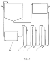
- FIG. 3 shows a schematic representation of a closed water cycle, as it is in fish farms.
- the waste water obtained in a fish silo 24 is first fed to a mechanical cleaning device 25.
- fish-toxic ammonium or ammonia is broken down to nitrite.
- the nitrite is converted into fish-nitrate.
- These first two biological treatment stages use aerobic bacteria. This is followed by the use of anaerobic bacteria and the fact that the oxygen has been completely consumed by the preceding process steps, the conversion of the nitrate into nitrogen.
- This last biological treatment step can also occur in the case of lime addition to the waste water.
- the organically contaminated wastewater is kept for a few minutes in order to enable the most complete possible reaction of the desired type. It is favorable to create particularly advantageous living and metabolic conditions in each biofilm reactor for the bacteria desired there. This can be done by targeted temperature control and / or targeted addition of nutrients or stimulants.
- conditioning 26 is provided for the treated wastewater. Oxygen enrichment, temperature control and pH adjustment of the waste water take place here before it reaches the fish silo 24 again as fresh water. Mechanical filtering of the biomass produced in the biofilm reactors 1 is generally not necessary.
- the water cycle shown in FIG. 3 can be operated almost without the addition of real fresh water ( ⁇ 5% / d) and thus represents a very environmentally friendly possibility for fish production.
Landscapes
- Life Sciences & Earth Sciences (AREA)
- Biodiversity & Conservation Biology (AREA)
- Water Supply & Treatment (AREA)
- Hydrology & Water Resources (AREA)
- Engineering & Computer Science (AREA)
- Environmental & Geological Engineering (AREA)
- Microbiology (AREA)
- Chemical & Material Sciences (AREA)
- Organic Chemistry (AREA)
- Environmental Sciences (AREA)
- Marine Sciences & Fisheries (AREA)
- Animal Husbandry (AREA)
- Biological Treatment Of Waste Water (AREA)
Applications Claiming Priority (2)
| Application Number | Priority Date | Filing Date | Title |
|---|---|---|---|
| DE9016202U | 1990-11-22 | ||
| DE9016202U DE9016202U1 (de) | 1990-11-22 | 1990-11-22 | Biofilter für die biologische Nitrifikation |
Publications (1)
| Publication Number | Publication Date |
|---|---|
| EP0486748A1 true EP0486748A1 (fr) | 1992-05-27 |
Family
ID=6859788
Family Applications (1)
| Application Number | Title | Priority Date | Filing Date |
|---|---|---|---|
| EP19910105364 Withdrawn EP0486748A1 (fr) | 1990-11-22 | 1991-04-04 | Procédé et réacteurs à film biologique pour le traitement d'eau usée chargée d'impuretés organiques |
Country Status (2)
| Country | Link |
|---|---|
| EP (1) | EP0486748A1 (fr) |
| DE (1) | DE9016202U1 (fr) |
Cited By (5)
| Publication number | Priority date | Publication date | Assignee | Title |
|---|---|---|---|---|
| GB2334029A (en) * | 1998-02-04 | 1999-08-11 | John James Todd | Media for waste water treatment |
| EP1757561A3 (fr) * | 2005-08-23 | 2007-05-02 | Hozelock Limited | Filtres à bassin |
| WO2019121285A1 (fr) * | 2017-12-22 | 2019-06-27 | Jassen - Kunststoffzentrum Gmbh - Apparatebau, Zuschnitte Und Formung | Bioréacteur et son utilisation, procédé de production d'une solution nutritive organique, solution nutritive organique, matière de substrat et son utilisation pour la culture des végétaux |
| WO2020254242A1 (fr) * | 2019-06-17 | 2020-12-24 | Jassen - Kunststoffzentrum Gmbh - Apparatebau, Zuschnitte Und Formung | Bioréacteur et son utilisation, et procédé de fabrication d'une solution nutritive organique et de stockage de dioxyde de carbone |
| US20210162343A1 (en) * | 2019-12-03 | 2021-06-03 | Bonno Koers | Method and device for removing ammonia from exhaust air from a livestock stable |
Families Citing this family (2)
| Publication number | Priority date | Publication date | Assignee | Title |
|---|---|---|---|---|
| DE9016202U1 (de) * | 1990-11-22 | 1991-03-28 | Meylahn, Gerd-Uwe, Dr., O-1501 Groß-Glienicke | Biofilter für die biologische Nitrifikation |
| DE4214004C1 (en) * | 1992-04-29 | 1993-05-19 | Fischtechnik Fredelsloh, Dr. Gerhard Mueller Gmbh, 3413 Moringen, De | Bio-film reactor for biological treatment of waste water - comprising vertical reaction chamber contg. perforated impact wall to separate biomass |
Citations (8)
| Publication number | Priority date | Publication date | Assignee | Title |
|---|---|---|---|---|
| US3779906A (en) * | 1972-08-03 | 1973-12-18 | Biospherics Inc | Plastic moving-surface treatment of sewage |
| US4009099A (en) * | 1974-07-12 | 1977-02-22 | Ecolotrol, Inc. | Apparatus and process for removing ammonia nitrogen from waste water |
| FR2446259A1 (fr) * | 1979-01-12 | 1980-08-08 | Degremont | Procede et appareil pour l'elimination de la pollution azotee des eaux |
| EP0124409A1 (fr) * | 1983-04-28 | 1984-11-07 | L'air Liquide, Societe Anonyme Pour L'etude Et L'exploitation Des Procedes Georges Claude | Procédé et dispositif de régénération d'un ensemble de particules solides à enrobage en matière biologique |
| DD238373A1 (de) * | 1985-06-19 | 1986-08-20 | Tech Hochschule C Schorlemmer | Verfahren zur biologischen denitrifikation |
| DE3518490A1 (de) * | 1985-05-23 | 1986-11-27 | WSW Planungsgesellschaft mbH, 4355 Waltrop | Einrichtung zur biologischen abwasserbehandlung |
| EP0389958A1 (fr) * | 1989-03-25 | 1990-10-03 | Preussag Aktiengesellschaft | Procédé pour le traitement biochimique d'eau |
| DE9016202U1 (de) * | 1990-11-22 | 1991-03-28 | Meylahn, Gerd-Uwe, Dr., O-1501 Groß-Glienicke | Biofilter für die biologische Nitrifikation |
-
1990
- 1990-11-22 DE DE9016202U patent/DE9016202U1/de not_active Expired - Lifetime
-
1991
- 1991-04-04 EP EP19910105364 patent/EP0486748A1/fr not_active Withdrawn
Patent Citations (8)
| Publication number | Priority date | Publication date | Assignee | Title |
|---|---|---|---|---|
| US3779906A (en) * | 1972-08-03 | 1973-12-18 | Biospherics Inc | Plastic moving-surface treatment of sewage |
| US4009099A (en) * | 1974-07-12 | 1977-02-22 | Ecolotrol, Inc. | Apparatus and process for removing ammonia nitrogen from waste water |
| FR2446259A1 (fr) * | 1979-01-12 | 1980-08-08 | Degremont | Procede et appareil pour l'elimination de la pollution azotee des eaux |
| EP0124409A1 (fr) * | 1983-04-28 | 1984-11-07 | L'air Liquide, Societe Anonyme Pour L'etude Et L'exploitation Des Procedes Georges Claude | Procédé et dispositif de régénération d'un ensemble de particules solides à enrobage en matière biologique |
| DE3518490A1 (de) * | 1985-05-23 | 1986-11-27 | WSW Planungsgesellschaft mbH, 4355 Waltrop | Einrichtung zur biologischen abwasserbehandlung |
| DD238373A1 (de) * | 1985-06-19 | 1986-08-20 | Tech Hochschule C Schorlemmer | Verfahren zur biologischen denitrifikation |
| EP0389958A1 (fr) * | 1989-03-25 | 1990-10-03 | Preussag Aktiengesellschaft | Procédé pour le traitement biochimique d'eau |
| DE9016202U1 (de) * | 1990-11-22 | 1991-03-28 | Meylahn, Gerd-Uwe, Dr., O-1501 Groß-Glienicke | Biofilter für die biologische Nitrifikation |
Cited By (12)
| Publication number | Priority date | Publication date | Assignee | Title |
|---|---|---|---|---|
| GB2334029A (en) * | 1998-02-04 | 1999-08-11 | John James Todd | Media for waste water treatment |
| EP1757561A3 (fr) * | 2005-08-23 | 2007-05-02 | Hozelock Limited | Filtres à bassin |
| WO2019121285A1 (fr) * | 2017-12-22 | 2019-06-27 | Jassen - Kunststoffzentrum Gmbh - Apparatebau, Zuschnitte Und Formung | Bioréacteur et son utilisation, procédé de production d'une solution nutritive organique, solution nutritive organique, matière de substrat et son utilisation pour la culture des végétaux |
| CN111492048A (zh) * | 2017-12-22 | 2020-08-04 | 扎森器具切割和定型塑胶中心有限公司 | 生物反应器及其用途,用于制备有机营养溶液的方法,有机营养溶液,基质材料及其用于培养植物的用途 |
| AU2018391487B2 (en) * | 2017-12-22 | 2020-12-10 | Jassen - Kunststoffzentrum Gmbh - Apparatebau, Zuschnitte Und Formung | Bioreactor and use thereof, method for producing an organic nutrient solution, organic nutrient solution, substrate material and use thereof for cultivating plants |
| RU2759844C1 (ru) * | 2017-12-22 | 2021-11-18 | Яссен - Кунстштоффцентрум ГмбХ - Аппаратебау, Цушнитте унд Формунг | Биореактор и его применение, способ получения органического питательного раствора, органический питательный раствор, субстратный материал и его применение для культивирования растений |
| CN111492048B (zh) * | 2017-12-22 | 2022-08-19 | 扎森器具切割和定型塑胶中心有限公司 | 生物反应器用于制备有机营养溶液的方法 |
| US11672214B2 (en) | 2017-12-22 | 2023-06-13 | Jassen—Kunststoffzentrum GmbH—Apparatebau, Zuschnitte und Formung | Bioreactor and use thereof, method for producing an organic nutrient solution, organic nutrient solution, substrate material and use thereof for cultivating plants |
| WO2020254242A1 (fr) * | 2019-06-17 | 2020-12-24 | Jassen - Kunststoffzentrum Gmbh - Apparatebau, Zuschnitte Und Formung | Bioréacteur et son utilisation, et procédé de fabrication d'une solution nutritive organique et de stockage de dioxyde de carbone |
| CN114341334A (zh) * | 2019-06-17 | 2022-04-12 | 扎森器具切割和定型塑胶中心有限公司 | 生物反应器及其应用,用于制备有机营养液和用于存储二氧化碳的方法 |
| US12473240B2 (en) | 2019-06-17 | 2025-11-18 | Jassen-Kunststoffzentrum GmbH—Apparatebau, Zuschnitte und Formung | Bioreactor and use thereof, method for producing an organic nutrient solution and for carbon dioxide storage |
| US20210162343A1 (en) * | 2019-12-03 | 2021-06-03 | Bonno Koers | Method and device for removing ammonia from exhaust air from a livestock stable |
Also Published As
| Publication number | Publication date |
|---|---|
| DE9016202U1 (de) | 1991-03-28 |
Similar Documents
| Publication | Publication Date | Title |
|---|---|---|
| DE2721723A1 (de) | Belebtschlammverfahren zur abwasseraufbereitung und vorrichtung zur durchfuehrung des verfahrens | |
| WO1990002100A1 (fr) | Dispositif et procede d'epuration microbiologique de l'eau | |
| DE3427448A1 (de) | Verfahren und vorrichtung zur biologischen abwasserreinigung | |
| DE69000620T2 (de) | Verfahren zur anlage zur biologischen abwasserreinigung, speziell zur nitrifikation und/oder denitrifikation von stickstoffhaltigem abwasser. | |
| DE2237929C2 (de) | Verfahren zum Entfernen von Verunreinigungen aus einem Abgas | |
| DE4110026A1 (de) | Biologische klaeranlage mit biologisch inertem gasumlauf | |
| EP0389958B1 (fr) | Procédé pour le traitement biochimique d'eau | |
| EP0486748A1 (fr) | Procédé et réacteurs à film biologique pour le traitement d'eau usée chargée d'impuretés organiques | |
| CH616639A5 (en) | Process and apparatus for removing ammonia nitrogen from effluents | |
| DE4415637C2 (de) | Verfahren und Vorrichtung zur Klärung und Aufbereitung von Waschwassern aus Fahrzeugwaschanlagen | |
| DE2033669A1 (de) | Verfahren und Vorrichtung zum Be handeln von Abwasser oder dergl | |
| DE10043595B4 (de) | Wasserfilter | |
| DE3508916A1 (de) | Verfahren und anlage zum reinigen von abwasser | |
| CH644569A5 (de) | Verfahren und vorrichtung zum behandeln von abwasser. | |
| WO1982002874A1 (fr) | Procede, dispositif et moyen pour l'epuration des eaux usees | |
| DE2420744C3 (de) | Vorrichtung zum Reinigen von Abwasser | |
| EP2100856B1 (fr) | Procédé de traitement biologique de l'eau | |
| EP0501355B1 (fr) | Processus de traitement anaérobie de l'eau, notamment de l'élimination par micro-organismes du nitrate de l'eau potable | |
| DE2936826A1 (de) | Verfahren und vorrichtung zur biologischen reinigung von abwasser | |
| EP0659695B1 (fr) | Procédé pour le traitement des boues des eaux d'égou | |
| DE3517600A1 (de) | Verfahren und vorrichtung zur aeroben reinigung von abwaessern | |
| CH685429A5 (de) | Biologisches Abluftreinigungsverfahren. | |
| DE102023209401B4 (de) | Aquakulturanlage, Fischproduktion und Verfahren zum Betreiben einer Aquakulturanlage | |
| CH667641A5 (de) | Verfahren zur autotrophen denitrifikation von wasser. | |
| EP0503546A1 (fr) | Procédé pour la purification biologique d'eau |
Legal Events
| Date | Code | Title | Description |
|---|---|---|---|
| PUAI | Public reference made under article 153(3) epc to a published international application that has entered the european phase |
Free format text: ORIGINAL CODE: 0009012 |
|
| AK | Designated contracting states |
Kind code of ref document: A1 Designated state(s): DE DK ES GB NL SE |
|
| 17P | Request for examination filed |
Effective date: 19920709 |
|
| 17Q | First examination report despatched |
Effective date: 19930303 |
|
| STAA | Information on the status of an ep patent application or granted ep patent |
Free format text: STATUS: THE APPLICATION IS DEEMED TO BE WITHDRAWN |
|
| 18D | Application deemed to be withdrawn |
Effective date: 19930913 |