EP0486765A1 - Eolienne - Google Patents
Eolienne Download PDFInfo
- Publication number
- EP0486765A1 EP0486765A1 EP91113402A EP91113402A EP0486765A1 EP 0486765 A1 EP0486765 A1 EP 0486765A1 EP 91113402 A EP91113402 A EP 91113402A EP 91113402 A EP91113402 A EP 91113402A EP 0486765 A1 EP0486765 A1 EP 0486765A1
- Authority
- EP
- European Patent Office
- Prior art keywords
- generator
- brake
- machine according
- wind
- power machine
- Prior art date
- Legal status (The legal status is an assumption and is not a legal conclusion. Google has not performed a legal analysis and makes no representation as to the accuracy of the status listed.)
- Granted
Links
Images

Classifications
-
- F—MECHANICAL ENGINEERING; LIGHTING; HEATING; WEAPONS; BLASTING
- F03—MACHINES OR ENGINES FOR LIQUIDS; WIND, SPRING, OR WEIGHT MOTORS; PRODUCING MECHANICAL POWER OR A REACTIVE PROPULSIVE THRUST, NOT OTHERWISE PROVIDED FOR
- F03D—WIND MOTORS
- F03D7/00—Controlling wind motors
- F03D7/02—Controlling wind motors the wind motors having rotation axis substantially parallel to the air flow entering the rotor
- F03D7/0244—Controlling wind motors the wind motors having rotation axis substantially parallel to the air flow entering the rotor for braking
- F03D7/0248—Controlling wind motors the wind motors having rotation axis substantially parallel to the air flow entering the rotor for braking by mechanical means acting on the power train
-
- F—MECHANICAL ENGINEERING; LIGHTING; HEATING; WEAPONS; BLASTING
- F05—INDEXING SCHEMES RELATING TO ENGINES OR PUMPS IN VARIOUS SUBCLASSES OF CLASSES F01-F04
- F05B—INDEXING SCHEME RELATING TO WIND, SPRING, WEIGHT, INERTIA OR LIKE MOTORS, TO MACHINES OR ENGINES FOR LIQUIDS COVERED BY SUBCLASSES F03B, F03D AND F03G
- F05B2220/00—Application
- F05B2220/70—Application in combination with
- F05B2220/706—Application in combination with an electrical generator
-
- F—MECHANICAL ENGINEERING; LIGHTING; HEATING; WEAPONS; BLASTING
- F05—INDEXING SCHEMES RELATING TO ENGINES OR PUMPS IN VARIOUS SUBCLASSES OF CLASSES F01-F04
- F05B—INDEXING SCHEME RELATING TO WIND, SPRING, WEIGHT, INERTIA OR LIKE MOTORS, TO MACHINES OR ENGINES FOR LIQUIDS COVERED BY SUBCLASSES F03B, F03D AND F03G
- F05B2260/00—Function
- F05B2260/90—Braking
- F05B2260/903—Braking using electrical or magnetic forces
-
- Y—GENERAL TAGGING OF NEW TECHNOLOGICAL DEVELOPMENTS; GENERAL TAGGING OF CROSS-SECTIONAL TECHNOLOGIES SPANNING OVER SEVERAL SECTIONS OF THE IPC; TECHNICAL SUBJECTS COVERED BY FORMER USPC CROSS-REFERENCE ART COLLECTIONS [XRACs] AND DIGESTS
- Y02—TECHNOLOGIES OR APPLICATIONS FOR MITIGATION OR ADAPTATION AGAINST CLIMATE CHANGE
- Y02E—REDUCTION OF GREENHOUSE GAS [GHG] EMISSIONS, RELATED TO ENERGY GENERATION, TRANSMISSION OR DISTRIBUTION
- Y02E10/00—Energy generation through renewable energy sources
- Y02E10/70—Wind energy
- Y02E10/72—Wind turbines with rotation axis in wind direction
Definitions
- This object is achieved in a wind power machine which is provided with at least one non-contact brake operating on the induction principle.
- a particular advantage of the brake according to the invention is that the braking takes place contactlessly and practically without wear and that speed regulation is additionally possible by metering the braking power.
- at least one yoke plate with at least one coil arranged thereon, as well as the stator of the generator, is fixedly arranged, and an armature, arranged by the coils while maintaining an air gap, and the rotor of the generator are rotatably connected to a shaft.
- the number of yoke plates and coils is designed so that it corresponds to the braking forces that occur.
- the yoke plate is connected to the fixed part and the armature to the rotating part of the wind turbine.
- the yoke plate can be fixed on the stator and the armature on the same drive shaft as the rotor.
- the armature on the high-speed drive shaft of a gearbox and the yoke plate directly in front of it can also be used be arranged.
- the anchor is preferably designed as a solid iron disc.
- the nominal power (current, voltage, frequency) of the generator increases with the nominal speed. This excess, undesired energy is fed to the coils arranged on the yoke plate in such a way that the eddy current brake achieves a continuous and soft braking to the nominal speed. With an optimal angle of attack of the rotor blades of the wind turbine, a complex mechanical blade adjustment can therefore be dispensed with.
- one or more eddy current brakes can be attached to the free shaft end, in accordance with the required braking power.
- the eddy current brakes are usually fed with DC voltage and regulated according to the wind conditions, so that the braking power is increased or decreased in each case.
- the braking power can be controlled via the applied voltage, via the fed-in current or mechanically, e.g. by adjusting the air gap width.
- An eddy current brake is a brake that uses the effect of eddy currents (induction currents) in extensive metal masses.
- eddy currents are generated by variable magnetic fields. They can have considerable strength in the iron parts of electrical machines. For example, if you allow a thick copper disc to oscillate freely between the poles of a strong electromagnet and excite the electromagnet, the copper disc remains between due to the effect of the magnetic field on the induction currents occurring in the disc stuck to the poles like in a very viscous liquid. The kinetic energy of the pendulum is converted into heat in the copper disc. This can only be pulled out between the poles with considerable force and is heated up several times with violent back and forth movements. Accordingly, it is usually a technical task to prevent useless energy-consuming eddy currents in the iron parts of electrical machines.
- this phenomenon can also be used to generate a braking torque, as is used for so-called eddy current brakes.
- the armature By designing the armature as a solid iron disc with coils arranged in front of it on the yoke plate, it is also possible to use the brake as a holding brake. This means that the mechanically required holding brakes can also be dispensed with.
- a pole-changing generator which has separate windings can also be used in such wind power generators.
- One winding is used as the main generator in low winds and the other in normal winds.
- the currently free winding is used as a brake winding.
- a second separate braking system is usually required for wind power generators.
- the one braking system, an eddy current brake and that other braking system may be a winding brake. Both can be operated from a battery station or from a DC power supply. It is also possible for both brake systems to work in parallel thanks to an integrated control.
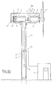
- FIGS. 1a and 1b A wind turbine 100, which is used to generate electrical current, is shown in FIGS. 1a and 1b.
- a wind turbine 1 is placed on a main shaft 8, which projects into a housing 9 and is connected to a transmission 2, the drive shaft 8 'of which is connected to a generator 3 via a clutch 10.
- the generator 3 in turn has a drive shaft 8 ′′, which is connected to an eddy current brake 4.
- the housing 9 is placed on a platform 5 which is rotatably arranged on a mast 12.
- the power generated by the generator 3 is fed into the electrical network via a line 13 and corresponding transition switching devices (not shown).
- the eddy current brake 4 is controlled via a line 14, which is connected to a battery 16 via a control element 15.
- the parts required for control are provided in a control cabinet 7.
- the eddy current brake 4 as a braking and control device basically consists of an excitation system and an armature disk.
- the excitation system represents a yoke plate 17 which carries coils 18, while the armature disk is an armature 20 in the form of an iron disk.
- the yoke plate 18 with the coils 17 is attached to the stator of the generator 3, the armature 20 at the end of the shaft 8 ′′ of the rotor of the generator 3.
- the yoke plate 18 carrying the coils 17 can be arranged on the housing of the transmission 2 and the armature 20 on the drive shaft 8 '. It is also possible to arrange two or more such induction brakes 4 individually or next to one another at the locations mentioned.
- the coils 18 have changing polarity according to FIG. They are excited by a direct current and generate a magnetic field B.
- the strength of the magnetic field B depends on the strength of the direct current.
- the armature 20 rotates in front of the coils 18 while maintaining an air gap. If a conductor is moved at a certain speed by a magnetic field, a voltage is induced and a movement-inhibiting effect acts on the moving conductor Force. By rotating the armature 20 instead of the conductor through the magnetic field B, the induced voltage leads to currents which close within the armature 20 to so-called eddy currents. These generate a braking force F B that is proportional to the square of the magnetic field B times the nominal speed n.
- a predetermined value e.
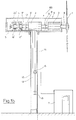
- the structure of a further embodiment of the eddy current brake 4 can be seen from the section on the left side of FIG. 1b.
- the eddy current brake 4 is connected here to the shaft 8 '''via a coupling 10.
- the induction coils 17, 18 are arranged on the shaft 8 '''and can be powered by the 24 V battery.
- the coils are surrounded by fixed armatures 20 '.
- the induction lines run opposite each other within the armatures 20 ', so that opposite torques are formed which lead to a strong braking of the rotating system inside the armatures.
- the braking power or the braking torque is to be metered.
- a cooling jacket (not shown) can also be arranged around the armature 20 ′, which dissipates the resulting induction heat with the aid of the water flowing through it. The heated water can be used for heating.
- the generator 3 can be switched so that it is provided with an inductive brake system.
- This can be a pole-changing generator.
- one of the two of the windings can be used as a brake winding in which a direct current acting counter to the direction of rotation is sent through the winding. Control is also possible here.
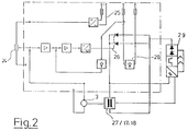
- the speed can be regulated with the aid of a voltage or current regulator according to FIG. 2.
- a setpoint generator 24 is acted upon by a sensor 25.
- the actual value is sampled at generator 3 via a corresponding speed sensor.
- the speed difference is used via a speed controller, current controller, pulse generator and control and braking electronics 29 to control two thyristors 26 that control the induction coils 27, which are located, for example, in the winding of the generator that is not currently required or in a separate eddy current brake . Accordingly, it can also be the coils 17, 18, 18 ', as already explained.
- an overvoltage protection 28 can also be provided, with which the current regulator can also be acted on, so that, for example, the induction coils are also addressed in the event of an overload.
- the brake system is located on the transmission or generator shaft (8 or 8 '' ').
- the braking torque required is mechanically and electrically adapted to the respective generator output. If full braking is necessary, for example in the event of an overload, the brake set is supplied with the full electrical conduction energy.
- the induction coils of the eddy current brake are each supplied with a specific and regulated partial energy that has to be adapted to the wind force and the nominal speed.
- the energy for the control of the eddy current brakes can be taken from the generator 3 in connection with a rectifier or conventional direct current accumulators. If there are several wind turbines, several systems can also be coupled accordingly.
- the second system is installed in the generator itself, specifically as a winding of the pole-changing generator, with the energy supplied being adapted to the respective generator size.
- a wear-free braking and control effect is guaranteed with this system and considerably simplifies the construction of such wind turbines.
- Both possible braking systems can therefore be used side by side.
Landscapes
- Engineering & Computer Science (AREA)
- Life Sciences & Earth Sciences (AREA)
- Sustainable Development (AREA)
- Sustainable Energy (AREA)
- Chemical & Material Sciences (AREA)
- Combustion & Propulsion (AREA)
- Mechanical Engineering (AREA)
- General Engineering & Computer Science (AREA)
- Wind Motors (AREA)
- Stopping Of Electric Motors (AREA)
- Braking Arrangements (AREA)
- Control Of Eletrric Generators (AREA)
Applications Claiming Priority (2)
| Application Number | Priority Date | Filing Date | Title |
|---|---|---|---|
| DE9015887U | 1990-11-22 | ||
| DE9015887U DE9015887U1 (de) | 1990-11-22 | 1990-11-22 | Windkraftmaschine |
Publications (2)
| Publication Number | Publication Date |
|---|---|
| EP0486765A1 true EP0486765A1 (fr) | 1992-05-27 |
| EP0486765B1 EP0486765B1 (fr) | 1994-10-19 |
Family
ID=6859566
Family Applications (1)
| Application Number | Title | Priority Date | Filing Date |
|---|---|---|---|
| EP91113402A Expired - Lifetime EP0486765B1 (fr) | 1990-11-22 | 1991-08-09 | Eolienne |
Country Status (3)
| Country | Link |
|---|---|
| EP (1) | EP0486765B1 (fr) |
| DE (2) | DE9015887U1 (fr) |
| DK (1) | DK0486765T3 (fr) |
Cited By (11)
| Publication number | Priority date | Publication date | Assignee | Title |
|---|---|---|---|---|
| DE19634464A1 (de) * | 1995-08-28 | 1997-04-03 | Lothar Kloft | Bremseinrichtung einer Windkraftanlage und Verfahren zu deren Betätigung |
| FR2753019A1 (fr) * | 1996-09-05 | 1998-03-06 | Schneider Electric Sa | Dispositif de production d'energie electrique |
| WO2003021105A1 (fr) * | 2001-09-04 | 2003-03-13 | Neue Spulentechnologie Beteiligungs Ag | Mecanisme moteur a ecoulement |
| WO2004042227A1 (fr) * | 2002-11-08 | 2004-05-21 | Reichen, Werner | Machine synchrone a champ axial excite par aimant permanent dans une installation d'energie eolienne |
| WO2004092579A1 (fr) * | 2003-04-15 | 2004-10-28 | Renergys Gmbh | Dispositif d'alimentation en energie destine a une installation eolienne |
| AT500843B1 (de) * | 2005-03-18 | 2006-04-15 | Hehenberger Gerald Dipl Ing | Verfahren und vorrichtung zum abbremsen des rotors einer windkraftanlage |
| NL2004922A (nl) * | 2009-06-18 | 2010-12-20 | Everkinetlq Benelux B V | Elektriciteitsgenerator en werkwijze. |
| FR2988782A1 (fr) * | 2012-03-30 | 2013-10-04 | Eolys Ressources Et En | Aerogenerateur comprenant un ralentisseur electro-magnetique pour ralentir la vitesse de rotations des pales |
| US20140110947A1 (en) * | 2012-10-24 | 2014-04-24 | Vestas Wind Systems A/S | Wind turbine generator having an eddy current brake, wind turbine having such a generator, and associated methods |
| WO2014181349A3 (fr) * | 2013-04-25 | 2015-02-26 | Rajagopal Raghunathan Valagam | Système de freinage de turbine éolienne utilisant le freinage de courant de foucault |
| AT515934A4 (de) * | 2014-09-22 | 2016-01-15 | Gerald Dipl Ing Hehenberger | Antriebsstrang einer Energiegewinnungsanlage |
Families Citing this family (2)
| Publication number | Priority date | Publication date | Assignee | Title |
|---|---|---|---|---|
| DE19629168C1 (de) * | 1996-07-19 | 1997-10-30 | Voith Turbo Kg | Windturbine mit einem Turm, einer Gondel und einer Bremse zum Arretieren der Schwenkbewegung der Gondel |
| US7948100B2 (en) * | 2007-12-19 | 2011-05-24 | General Electric Company | Braking and positioning system for a wind turbine rotor |
Citations (3)
| Publication number | Priority date | Publication date | Assignee | Title |
|---|---|---|---|---|
| FR678780A (fr) * | 1929-07-19 | 1930-04-04 | Perfectionnement au réglage des machines commandées par des moteurs à vent | |
| FR2355178A1 (fr) * | 1976-06-18 | 1978-01-13 | Anvar | Dispositif regule de production d'energie electrique, tel que dispositif eolien |
| BE902092A (fr) * | 1985-04-02 | 1985-07-31 | Emega Sa | Eolienne equipee d'un generateur du type a entrefer axial en forme de disque, auto-excite par aimants permanents et ne contenant pas de fer dans l'induit |
-
1990
- 1990-11-22 DE DE9015887U patent/DE9015887U1/de not_active Expired - Lifetime
-
1991
- 1991-08-09 DE DE59103281T patent/DE59103281D1/de not_active Expired - Fee Related
- 1991-08-09 DK DK91113402.1T patent/DK0486765T3/da active
- 1991-08-09 EP EP91113402A patent/EP0486765B1/fr not_active Expired - Lifetime
Patent Citations (3)
| Publication number | Priority date | Publication date | Assignee | Title |
|---|---|---|---|---|
| FR678780A (fr) * | 1929-07-19 | 1930-04-04 | Perfectionnement au réglage des machines commandées par des moteurs à vent | |
| FR2355178A1 (fr) * | 1976-06-18 | 1978-01-13 | Anvar | Dispositif regule de production d'energie electrique, tel que dispositif eolien |
| BE902092A (fr) * | 1985-04-02 | 1985-07-31 | Emega Sa | Eolienne equipee d'un generateur du type a entrefer axial en forme de disque, auto-excite par aimants permanents et ne contenant pas de fer dans l'induit |
Cited By (15)
| Publication number | Priority date | Publication date | Assignee | Title |
|---|---|---|---|---|
| DE19634464A1 (de) * | 1995-08-28 | 1997-04-03 | Lothar Kloft | Bremseinrichtung einer Windkraftanlage und Verfahren zu deren Betätigung |
| DE19634464C2 (de) * | 1995-08-28 | 1998-07-16 | Lothar Kloft | Bremseinrichtung einer Windkraftanlage und Verfahren zu deren Betätigung |
| FR2753019A1 (fr) * | 1996-09-05 | 1998-03-06 | Schneider Electric Sa | Dispositif de production d'energie electrique |
| WO2003021105A1 (fr) * | 2001-09-04 | 2003-03-13 | Neue Spulentechnologie Beteiligungs Ag | Mecanisme moteur a ecoulement |
| WO2004042227A1 (fr) * | 2002-11-08 | 2004-05-21 | Reichen, Werner | Machine synchrone a champ axial excite par aimant permanent dans une installation d'energie eolienne |
| WO2004092579A1 (fr) * | 2003-04-15 | 2004-10-28 | Renergys Gmbh | Dispositif d'alimentation en energie destine a une installation eolienne |
| AT500843B1 (de) * | 2005-03-18 | 2006-04-15 | Hehenberger Gerald Dipl Ing | Verfahren und vorrichtung zum abbremsen des rotors einer windkraftanlage |
| NL2004922A (nl) * | 2009-06-18 | 2010-12-20 | Everkinetlq Benelux B V | Elektriciteitsgenerator en werkwijze. |
| FR2988782A1 (fr) * | 2012-03-30 | 2013-10-04 | Eolys Ressources Et En | Aerogenerateur comprenant un ralentisseur electro-magnetique pour ralentir la vitesse de rotations des pales |
| EP2657516A1 (fr) * | 2012-03-30 | 2013-10-30 | Eolys Ressources et Energies | Aérogénérateur comprenant un ralentisseur électro-magnétique pour ralentir la vitesse de rotations des pales |
| US20140110947A1 (en) * | 2012-10-24 | 2014-04-24 | Vestas Wind Systems A/S | Wind turbine generator having an eddy current brake, wind turbine having such a generator, and associated methods |
| US9518562B2 (en) | 2012-10-24 | 2016-12-13 | Vestas Wind Systems A/S | Wind turbine generator having an eddy current brake, wind turbine having such a generator, and associated methods |
| WO2014181349A3 (fr) * | 2013-04-25 | 2015-02-26 | Rajagopal Raghunathan Valagam | Système de freinage de turbine éolienne utilisant le freinage de courant de foucault |
| AT515934A4 (de) * | 2014-09-22 | 2016-01-15 | Gerald Dipl Ing Hehenberger | Antriebsstrang einer Energiegewinnungsanlage |
| AT515934B1 (de) * | 2014-09-22 | 2016-01-15 | Gerald Dipl Ing Hehenberger | Antriebsstrang einer Energiegewinnungsanlage |
Also Published As
| Publication number | Publication date |
|---|---|
| EP0486765B1 (fr) | 1994-10-19 |
| DK0486765T3 (da) | 1995-04-10 |
| DE9015887U1 (de) | 1991-04-18 |
| DE59103281D1 (de) | 1994-11-24 |
Similar Documents
| Publication | Publication Date | Title |
|---|---|---|
| EP1997214B1 (fr) | Machine électrique notamment générateur | |
| DE69008538T2 (de) | Windturbine. | |
| EP0486765A1 (fr) | Eolienne | |
| EP2859222B1 (fr) | Installation de production d'énergie, en particulier éolienne | |
| EP3110739B1 (fr) | Grue | |
| DE6918595U (de) | Hilfsstromaggregat | |
| DE102009046883A1 (de) | Pitchantriebsvorrichtung für eine Wind- oder Wasserkraftanlage | |
| DE1044245B (de) | Steuergeraet fuer eine elektrische Kupplung | |
| DE3838579A1 (de) | Steuervorrichtung fuer einen permanentmagnet-synchronmotor | |
| DE4116160A1 (de) | Elektromagnetischer retarder | |
| DE102009032739A1 (de) | Werkzeugmaschine und Verfahren zum Betreiben einer solchen | |
| AT514170B1 (de) | Antriebsstrang einer Energiegewinnungsanlage und Verfahren zum Regeln | |
| AT515934B1 (de) | Antriebsstrang einer Energiegewinnungsanlage | |
| AT510119B1 (de) | Differenzialgetriebe für eine windkraftanlage und verfahren zum betreiben dieses differenzialgetriebes | |
| DE202008010748U1 (de) | Verstelleinrichtung für eine Windenergieanlage | |
| DE102008029377B4 (de) | Vorrichtung für eine Wind- oder Wasserkraftanlage zur Erzeugung elektrischer Energie | |
| DE860653C (de) | Elektrischer Umformersatz fuer ein Wechsel- oder Drehstrom-Windkraftwerk gleichbleibender Periodenzahl | |
| DE19938148C2 (de) | Elektromagnetische Antriebsvorrichtung | |
| DE102005050486B4 (de) | Energieumwandlungseinheit | |
| DE946304C (de) | Regeleinrichtung fuer selbsttaetig arbeitende Elektroden-Verstellvorrichtungen bei elektrischen Lichtbogen- und Reduktionsoefen | |
| DE630975C (de) | Vorrichtung zur elektrischen Regelung technisch-physikalischer Betriebsgroessen, insbesondere von Netzspannungen und Drehzahlen | |
| DE263020C (fr) | ||
| AT208469B (de) | Antrieb für Hebezeuge, Seilbahnen od. dgl. | |
| AT109594B (de) | Verfahren und Einrichtung zur Änderung der Charakteristik von Kaskaden. | |
| AT87768B (de) | Einrichtung zum Betrieb von Asynchronmotoren, die zur Verhinderung unzulässiger Tourensteigerungen bei negativer Belastung mittels Gleichstrom im Rotor erregt werden. |
Legal Events
| Date | Code | Title | Description |
|---|---|---|---|
| PUAI | Public reference made under article 153(3) epc to a published international application that has entered the european phase |
Free format text: ORIGINAL CODE: 0009012 |
|
| AK | Designated contracting states |
Kind code of ref document: A1 Designated state(s): BE DE DK FR NL SE |
|
| 17P | Request for examination filed |
Effective date: 19921007 |
|
| 17Q | First examination report despatched |
Effective date: 19930422 |
|
| GRAA | (expected) grant |
Free format text: ORIGINAL CODE: 0009210 |
|
| AK | Designated contracting states |
Kind code of ref document: B1 Designated state(s): BE DE DK FR NL SE |
|
| REF | Corresponds to: |
Ref document number: 59103281 Country of ref document: DE Date of ref document: 19941124 |
|
| ET | Fr: translation filed | ||
| EAL | Se: european patent in force in sweden |
Ref document number: 91113402.1 |
|
| REG | Reference to a national code |
Ref country code: DK Ref legal event code: T3 |
|
| PLBE | No opposition filed within time limit |
Free format text: ORIGINAL CODE: 0009261 |
|
| STAA | Information on the status of an ep patent application or granted ep patent |
Free format text: STATUS: NO OPPOSITION FILED WITHIN TIME LIMIT |
|
| 26N | No opposition filed | ||
| REG | Reference to a national code |
Ref country code: FR Ref legal event code: ST |
|
| REG | Reference to a national code |
Ref country code: FR Ref legal event code: RN |
|
| REG | Reference to a national code |
Ref country code: FR Ref legal event code: FC |
|
| PGFP | Annual fee paid to national office [announced via postgrant information from national office to epo] |
Ref country code: SE Payment date: 19980824 Year of fee payment: 8 |
|
| PGFP | Annual fee paid to national office [announced via postgrant information from national office to epo] |
Ref country code: BE Payment date: 19980908 Year of fee payment: 8 |
|
| PGFP | Annual fee paid to national office [announced via postgrant information from national office to epo] |
Ref country code: FR Payment date: 19990818 Year of fee payment: 9 |
|
| PGFP | Annual fee paid to national office [announced via postgrant information from national office to epo] |
Ref country code: NL Payment date: 19990819 Year of fee payment: 9 |
|
| PGFP | Annual fee paid to national office [announced via postgrant information from national office to epo] |
Ref country code: DK Payment date: 19990823 Year of fee payment: 9 |
|
| PG25 | Lapsed in a contracting state [announced via postgrant information from national office to epo] |
Ref country code: SE Free format text: THE PATENT HAS BEEN ANNULLED BY A DECISION OF A NATIONAL AUTHORITY Effective date: 19990830 |
|
| PG25 | Lapsed in a contracting state [announced via postgrant information from national office to epo] |
Ref country code: BE Free format text: LAPSE BECAUSE OF NON-PAYMENT OF DUE FEES Effective date: 19990831 |
|
| BERE | Be: lapsed |
Owner name: MROZ FRANZ Effective date: 19990831 |
|
| EUG | Se: european patent has lapsed |
Ref document number: 91113402.1 |
|
| PG25 | Lapsed in a contracting state [announced via postgrant information from national office to epo] |
Ref country code: DK Free format text: LAPSE BECAUSE OF NON-PAYMENT OF DUE FEES Effective date: 20000809 |
|
| PGFP | Annual fee paid to national office [announced via postgrant information from national office to epo] |
Ref country code: DE Payment date: 20000812 Year of fee payment: 10 |
|
| PG25 | Lapsed in a contracting state [announced via postgrant information from national office to epo] |
Ref country code: NL Free format text: LAPSE BECAUSE OF NON-PAYMENT OF DUE FEES Effective date: 20010301 |
|
| PG25 | Lapsed in a contracting state [announced via postgrant information from national office to epo] |
Ref country code: FR Free format text: LAPSE BECAUSE OF NON-PAYMENT OF DUE FEES Effective date: 20010430 |
|
| REG | Reference to a national code |
Ref country code: DK Ref legal event code: EBP |
|
| NLV4 | Nl: lapsed or anulled due to non-payment of the annual fee |
Effective date: 20010301 |
|
| REG | Reference to a national code |
Ref country code: FR Ref legal event code: ST |
|
| PG25 | Lapsed in a contracting state [announced via postgrant information from national office to epo] |
Ref country code: DE Free format text: LAPSE BECAUSE OF NON-PAYMENT OF DUE FEES Effective date: 20020501 |