EP0486785A2 - Rapidly changeable chucks for holding stators in stator processing apparatus - Google Patents
Rapidly changeable chucks for holding stators in stator processing apparatus Download PDFInfo
- Publication number
- EP0486785A2 EP0486785A2 EP91116070A EP91116070A EP0486785A2 EP 0486785 A2 EP0486785 A2 EP 0486785A2 EP 91116070 A EP91116070 A EP 91116070A EP 91116070 A EP91116070 A EP 91116070A EP 0486785 A2 EP0486785 A2 EP 0486785A2
- Authority
- EP
- European Patent Office
- Prior art keywords
- apparatus defined
- jaw member
- housing
- jaw
- stator
- Prior art date
- Legal status (The legal status is an assumption and is not a legal conclusion. Google has not performed a legal analysis and makes no representation as to the accuracy of the status listed.)
- Withdrawn
Links
Images



Classifications
-
- H—ELECTRICITY
- H02—GENERATION; CONVERSION OR DISTRIBUTION OF ELECTRIC POWER
- H02K—DYNAMO-ELECTRIC MACHINES
- H02K15/00—Processes or apparatus specially adapted for manufacturing, assembling, maintaining or repairing of dynamo-electric machines
- H02K15/08—Forming windings by laying conductors into or around core parts
- H02K15/095—Forming windings by laying conductors into or around core parts by laying conductors around salient poles
-
- Y—GENERAL TAGGING OF NEW TECHNOLOGICAL DEVELOPMENTS; GENERAL TAGGING OF CROSS-SECTIONAL TECHNOLOGIES SPANNING OVER SEVERAL SECTIONS OF THE IPC; TECHNICAL SUBJECTS COVERED BY FORMER USPC CROSS-REFERENCE ART COLLECTIONS [XRACs] AND DIGESTS
- Y10—TECHNICAL SUBJECTS COVERED BY FORMER USPC
- Y10S—TECHNICAL SUBJECTS COVERED BY FORMER USPC CROSS-REFERENCE ART COLLECTIONS [XRACs] AND DIGESTS
- Y10S279/00—Chucks or sockets
- Y10S279/906—Self grasping socket
-
- Y—GENERAL TAGGING OF NEW TECHNOLOGICAL DEVELOPMENTS; GENERAL TAGGING OF CROSS-SECTIONAL TECHNOLOGIES SPANNING OVER SEVERAL SECTIONS OF THE IPC; TECHNICAL SUBJECTS COVERED BY FORMER USPC CROSS-REFERENCE ART COLLECTIONS [XRACs] AND DIGESTS
- Y10—TECHNICAL SUBJECTS COVERED BY FORMER USPC
- Y10T—TECHNICAL SUBJECTS COVERED BY FORMER US CLASSIFICATION
- Y10T24/00—Buckles, buttons, clasps, etc.
- Y10T24/39—Cord and rope holders
- Y10T24/3969—Sliding part or wedge
- Y10T24/3976—Sliding ball
-
- Y—GENERAL TAGGING OF NEW TECHNOLOGICAL DEVELOPMENTS; GENERAL TAGGING OF CROSS-SECTIONAL TECHNOLOGIES SPANNING OVER SEVERAL SECTIONS OF THE IPC; TECHNICAL SUBJECTS COVERED BY FORMER USPC CROSS-REFERENCE ART COLLECTIONS [XRACs] AND DIGESTS
- Y10—TECHNICAL SUBJECTS COVERED BY FORMER USPC
- Y10T—TECHNICAL SUBJECTS COVERED BY FORMER US CLASSIFICATION
- Y10T24/00—Buckles, buttons, clasps, etc.
- Y10T24/39—Cord and rope holders
- Y10T24/3993—Ball or roller
-
- Y—GENERAL TAGGING OF NEW TECHNOLOGICAL DEVELOPMENTS; GENERAL TAGGING OF CROSS-SECTIONAL TECHNOLOGIES SPANNING OVER SEVERAL SECTIONS OF THE IPC; TECHNICAL SUBJECTS COVERED BY FORMER USPC CROSS-REFERENCE ART COLLECTIONS [XRACs] AND DIGESTS
- Y10—TECHNICAL SUBJECTS COVERED BY FORMER USPC
- Y10T—TECHNICAL SUBJECTS COVERED BY FORMER US CLASSIFICATION
- Y10T24/00—Buckles, buttons, clasps, etc.
- Y10T24/44—Clasp, clip, support-clamp, or required component thereof
- Y10T24/44641—Clasp, clip, support-clamp, or required component thereof having gripping member formed from, biased by, or mounted on resilient member
-
- Y—GENERAL TAGGING OF NEW TECHNOLOGICAL DEVELOPMENTS; GENERAL TAGGING OF CROSS-SECTIONAL TECHNOLOGIES SPANNING OVER SEVERAL SECTIONS OF THE IPC; TECHNICAL SUBJECTS COVERED BY FORMER USPC CROSS-REFERENCE ART COLLECTIONS [XRACs] AND DIGESTS
- Y10—TECHNICAL SUBJECTS COVERED BY FORMER USPC
- Y10T—TECHNICAL SUBJECTS COVERED BY FORMER US CLASSIFICATION
- Y10T279/00—Chucks or sockets
- Y10T279/17—Socket type
- Y10T279/17128—Self-grasping
- Y10T279/17162—Yielding detent
-
- Y—GENERAL TAGGING OF NEW TECHNOLOGICAL DEVELOPMENTS; GENERAL TAGGING OF CROSS-SECTIONAL TECHNOLOGIES SPANNING OVER SEVERAL SECTIONS OF THE IPC; TECHNICAL SUBJECTS COVERED BY FORMER USPC CROSS-REFERENCE ART COLLECTIONS [XRACs] AND DIGESTS
- Y10—TECHNICAL SUBJECTS COVERED BY FORMER USPC
- Y10T—TECHNICAL SUBJECTS COVERED BY FORMER US CLASSIFICATION
- Y10T403/00—Joints and connections
- Y10T403/60—Biased catch or latch
- Y10T403/602—Biased catch or latch by separate spring
Definitions
- This invention relates to apparatus for making stators for use in electric motors and the like. More particularly, the invention relates to chucks for holding stators during processing, said chucks being designed for rapid change when stators of different sizes are to be processed.
- U.S. patent application Serial No. 306,618, filed February 6, 1989 shows stator processing apparatus in which the stator is held in a chuck which is in turn mounted in a housing.
- the chuck has two parts, one of which is movable relative to the other to releasably grip a stator between those two parts.
- the two chuck parts can be removed from the housing by removing (or at least backing off) several screws, lifting out the chuck parts, putting in the new chuck parts, and replacing or retightening the screws.
- the entire housing and chuck may be removed from the associated stator processing apparatus by removing two screws. A new housing with new chuck parts can then be placed on the associated apparatus.
- Both of the foregoing chuck replacement techniques may have certain disadvantages. Both are potentially time-consuming and require tools to manipulate the screws. If the screws are removed, they may become lost, and time may be wasted finding suitable replacements. In the case in which the chuck parts are removed from the housing, they become two separate parts which may be difficult to keep together for future use. In the case in which the housing is removed with the chuck parts inside, a relatively large and expensive component must be handled and replaced.
- stator-holding chucks which can be changed more easily and rapidly than the prior art chucks, and which do not have the disadvantages associated with the prior art chucks.
- a chuck structure which includes a movable jaw member mounted on a fixed jaw member, which is in turn removably mountable on a housing structure.
- the movable jaw member is actuatable from outside the fixed jaw member, e.g., by actuator elements associated with the housing structure.
- the fixed jaw member may include means for properly orienting a stator for gripping by the jaw members.
- the fixed jaw member and the housing structure may have elements which cooperate to ensure proper orientation of the fixed jaw member relative to the housing.
- Releasable latch means may be provided for releasably latching the fixed jaw member into the housing.
- these latch means are preferably operable by hand so that no tools are required to change the chuck structure to accommodate stators of different sizes. Also, when these latches are released, the fixed jaw member and/or the housing may include means for automatically partially ejecting the chuck from the housing.
- FIG. 1 is an elevational view, partly in section, of an illustrative embodiment of apparatus constructed in accordance with this invention.
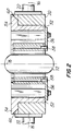
- FIG. 2 is a sectional view taken along the line 2-2 in FIG. 1.
- FIG. 3 is a partial sectional view taken along the line 3-3 in FIG. 1.
- FIG. 4 is a partial elevational view taken along the line 4-4 in FIG. 1.
- FIG. 5 is a partial sectional view taken along the line 5-5 in FIG. 1.
- FIG. 6 is an elevational view of the opposite side of the apparatus shown in FIG. 1.
- FIG. 7 is a partial sectional view taken along the line 7-7 in FIG. 6.
- Chuck apparatus 10 In the FIGS. the chuck apparatus 10 of this invention is shown holding a stator 12.
- Chuck apparatus 10 comprises three principal parts: a housing 20 which is permanent in the sense that it does not change when stators of different sizes are to be gripped; a fixed jaw member 50 which is removably mountable in housing 20; and a movable jaw member 80 which is captured in fixed jaw member 50 but which is movable relative to fixed jaw member 50 parallel to axis 14.
- Members 50 and 80 collectively comprise the chuck which is replaced as a unit when stators of different sizes (especially different diameters) are to be handled.
- housing 20 is shown supported by stub axles 22 for rotation about axis 16 in the manner in which the stator housings in above-mentioned U.S. application Serial No. 306,618 are rotatably mounted.
- Fixed jaw member 50 includes a hollow annular main body 52 having flanges 54 which project diametrically outward parallel to axis 16 at one axial end of the main body.
- the outer cylindrical surface of the portion of main body 52 below flanges 54 fits snugly but removably in a cylindrical aperture in housing 20.
- the lower surface of flanges 54 (as viewed in FIG. 2) bears on the upper surface of housing 20 to reference the chuck relative to housing 20 parallel to axis 18.
- stator 12 Before jaw 80 is moved to grip stator 12 between that jaw and the diametrically opposite portions of fixed jaw 50, stator 12 may be deposited in chuck 50/80 with one of its axial ends against stator stops 56.
- stops 56 are mounted on fixed jaw 50 and project into the interior of the fixed jaw adjacent one of its axal ends. Accordingly, stops 56 reference the stator relative to fixed jaw member 50 parallel to axis 18. Pins 58 on stops 56 extend into holes in the adjacent end of the stator to ensure proper angular orientation of the stator relative to the chuck. Pins 24 on housing 20 project into holes in flanges 54 to ensure proper angular orientation of fixed jaw 50 relative to the housing. Note that fixed jaw 50 is recessed away from stator 12 on diametrically opposite sides of the stator to facilitate insertion and removal of stators by means of spaced gripper arms (suggested by dotted lines 100) if desired.
- Chuck 50/80 is releasably latched into position in housing 20 by two spring-loaded latches 26 mounted on housing 20.
- each of latches 26 includes a latch finger 26a which is resiliently urged into a recess 26b in the adjacent flange 54 by a prestressed compression coil spring 26c.
- each latch finger 26a can be pushed out of the associated recess 26b by pushing on the associated latch actuator 26d.
- Manual pressure on latch actuators 26d is preferably sufficient to release the latches so that no tools are required for this operation.
- Movable jaw 80 is supported on fixed jaw 50 by two pins 82 which extend through jaw 50 into jaw 80.
- the ends of pins 82 are fixed in movable jaw 80 but are movable relative to jaw 50 parallel to their longitudinal axes (which coincide with or are parallel to axis 14). Accordingly, pins 82 move with jaw 80.
- Belleville washers 84 or other resilient means are provided under the enlarged heads of pins 82 for resiliently urging jaw 80 to retract from stator 12. In this way jaws 50 and 80 are biased toward the open position when the pressure from actuator structure 30 is removed as described below.
- Housing 20 carries a structure 30 for normally closing jaws 50 and 80 by pushing in on the heads of pins 82.
- Actuator structure 30 includes a bar 32 which is mounted on housing 20 by bushings 34 and bolts 36, which fasten bushings 34 to the housing.
- Prestressed compression coil springs 38 which act between bar 32 and the heads of bushings 34, resiliently urge bar 32 toward the heads of pins 82.
- the force of springs 38 is much greater than the force of springs 84. Accordingly, springs 38 provide the force required to close jaws 50 and 80 and to clamp stator 12 in those jaws.
- a roller 40 is mounted on each end of bar 32.
- rollers 40 may be pushed in the direction away from the heads of pins 82. For example, this may be done automatically at certain stations in the stator processing apparatus with which the depicted apparatus is used by running rollers 40 over suitably shaped cams at those stations.
- one or more wire grippers 90 can be mounted on housing 20 for releasably gripping the ends of wires (a representative wire 5 being shown in FIG. 7) wound on the poles of stator 12.
- Gripper 90 includes two opposing surfaces 92 and 94 for gripping a wire between them. Surfaces 92 and 94 are movable relative to one another, but are resiliently biased toward one another, e.g., by prestressed compression coil spring 96.
- each of members 92 and 94 which faces the other member is advantageously convex when viewed from the other member.
- Member 94 is conveniently constituted as a ball.
- Surface 92 may include a groove, notch, or seat 92a for receiving wire 5 and helping ball 94 releasably trap the wire.
- the force which spring 96 exerts on ball 94 may be adjusted by turning nut 98a relative to threaded spring retainer 98b.
- Gripper 90 can grip or release a wire without the need for a separate actuator to operate the gripper.
- gripper 90 could alternatively be mounted elsewhere on the apparatus, e.g., on fixed jaw member 50.
Landscapes
- Engineering & Computer Science (AREA)
- Manufacturing & Machinery (AREA)
- Power Engineering (AREA)
- Manufacture Of Motors, Generators (AREA)
Abstract
Description
- This invention relates to apparatus for making stators for use in electric motors and the like. More particularly, the invention relates to chucks for holding stators during processing, said chucks being designed for rapid change when stators of different sizes are to be processed.
- U.S. patent application Serial No. 306,618, filed February 6, 1989, shows stator processing apparatus in which the stator is held in a chuck which is in turn mounted in a housing. The chuck has two parts, one of which is movable relative to the other to releasably grip a stator between those two parts. When different size stators are to be processed, the two chuck parts can be removed from the housing by removing (or at least backing off) several screws, lifting out the chuck parts, putting in the new chuck parts, and replacing or retightening the screws. Alternatively, the entire housing and chuck may be removed from the associated stator processing apparatus by removing two screws. A new housing with new chuck parts can then be placed on the associated apparatus.
- Both of the foregoing chuck replacement techniques may have certain disadvantages. Both are potentially time-consuming and require tools to manipulate the screws. If the screws are removed, they may become lost, and time may be wasted finding suitable replacements. In the case in which the chuck parts are removed from the housing, they become two separate parts which may be difficult to keep together for future use. In the case in which the housing is removed with the chuck parts inside, a relatively large and expensive component must be handled and replaced.
- In view of the foregoing, it is an object of this invention to provide improved stator handling apparatus.
- It is a more particular object of this invention to provide stator-holding chucks which can be changed more easily and rapidly than the prior art chucks, and which do not have the disadvantages associated with the prior art chucks.
- These and other objects of the invention are accomplished in accordance with the principles of the invention by providing a chuck structure which includes a movable jaw member mounted on a fixed jaw member, which is in turn removably mountable on a housing structure. The movable jaw member is actuatable from outside the fixed jaw member, e.g., by actuator elements associated with the housing structure. The fixed jaw member may include means for properly orienting a stator for gripping by the jaw members. The fixed jaw member and the housing structure may have elements which cooperate to ensure proper orientation of the fixed jaw member relative to the housing. Releasable latch means may be provided for releasably latching the fixed jaw member into the housing. If provided, these latch means are preferably operable by hand so that no tools are required to change the chuck structure to accommodate stators of different sizes. Also, when these latches are released, the fixed jaw member and/or the housing may include means for automatically partially ejecting the chuck from the housing.
- Further features of the invention, its nature and various advantages will be more apparent from the accompanying drawings and the following detailed description of the preferred embodiments.
- FIG. 1 is an elevational view, partly in section, of an illustrative embodiment of apparatus constructed in accordance with this invention.
- FIG. 2 is a sectional view taken along the line 2-2 in FIG. 1.
- FIG. 3 is a partial sectional view taken along the line 3-3 in FIG. 1.
- FIG. 4 is a partial elevational view taken along the line 4-4 in FIG. 1.
- FIG. 5 is a partial sectional view taken along the line 5-5 in FIG. 1.
- FIG. 6 is an elevational view of the opposite side of the apparatus shown in FIG. 1.
- FIG. 7 is a partial sectional view taken along the line 7-7 in FIG. 6.
- Although it will be apparent to those skilled in the art that the apparatus of this invention can be used in other contexts, the invention will be fully understood from the following explanation of its application to apparatus of the type shown in U.S. patent application Serial No. 306,618, filed February 6, 1989.
- In the FIGS. the chuck apparatus 10 of this invention is shown holding a
stator 12. Chuck apparatus 10 comprises three principal parts: ahousing 20 which is permanent in the sense that it does not change when stators of different sizes are to be gripped; a fixedjaw member 50 which is removably mountable inhousing 20; and amovable jaw member 80 which is captured in fixedjaw member 50 but which is movable relative to fixedjaw member 50 parallel toaxis 14.Members - Although not necessary to the present invention,
housing 20 is shown supported bystub axles 22 for rotation aboutaxis 16 in the manner in which the stator housings in above-mentioned U.S. application Serial No. 306,618 are rotatably mounted. - Fixed
jaw member 50 includes a hollow annularmain body 52 havingflanges 54 which project diametrically outward parallel toaxis 16 at one axial end of the main body. The outer cylindrical surface of the portion ofmain body 52 belowflanges 54 fits snugly but removably in a cylindrical aperture inhousing 20. When thechuck 50/80 is fully positioned inhousing 20, the lower surface of flanges 54 (as viewed in FIG. 2) bears on the upper surface ofhousing 20 to reference the chuck relative tohousing 20 parallel toaxis 18. Beforejaw 80 is moved togrip stator 12 between that jaw and the diametrically opposite portions of fixedjaw 50,stator 12 may be deposited inchuck 50/80 with one of its axial ends againststator stops 56. These stops are mounted on fixedjaw 50 and project into the interior of the fixed jaw adjacent one of its axal ends. Accordingly, stops 56 reference the stator relative to fixedjaw member 50 parallel toaxis 18.Pins 58 onstops 56 extend into holes in the adjacent end of the stator to ensure proper angular orientation of the stator relative to the chuck.Pins 24 onhousing 20 project into holes inflanges 54 to ensure proper angular orientation of fixedjaw 50 relative to the housing. Note that fixedjaw 50 is recessed away fromstator 12 on diametrically opposite sides of the stator to facilitate insertion and removal of stators by means of spaced gripper arms (suggested by dotted lines 100) if desired. - Chuck 50/80 is releasably latched into position in
housing 20 by two spring-loadedlatches 26 mounted onhousing 20. As can best be seen in FIG. 3, each oflatches 26 includes alatch finger 26a which is resiliently urged into arecess 26b in theadjacent flange 54 by a prestressedcompression coil spring 26c. When it is desired to releasechuck 50/80 fromhousing 20, eachlatch finger 26a can be pushed out of the associatedrecess 26b by pushing on the associatedlatch actuator 26d. Manual pressure onlatch actuators 26d is preferably sufficient to release the latches so that no tools are required for this operation. Whenchuck 50/80 is in position inhousing 20, the inclined lower surface of the end of eachlatch finger 26a as viewed in FIG. 3 preferably exerts camming pressure on the inclined lower surface of the associatedrecess 26b in order to continually urge the lower surface offlanges 54 into firm contact with the upper surface ofhousing 20. Whenlatches 26 are released, spring-loaded pusher assemblies 28 automatically pushchuck 50/80 a short way out ofhousing 20, which facilitates further complete removal of the chuck from the housing (e.g., by exposingcavities 60 in the underside of flanges 54). Preferably the removal ofchuck 50/80 from housing 20 (and the replacement of that chuck with another one) can be done manually without the need for any tools. -
Movable jaw 80 is supported on fixedjaw 50 by twopins 82 which extend throughjaw 50 intojaw 80. The ends ofpins 82 are fixed inmovable jaw 80 but are movable relative tojaw 50 parallel to their longitudinal axes (which coincide with or are parallel to axis 14). Accordingly,pins 82 move withjaw 80. Bellevillewashers 84 or other resilient means are provided under the enlarged heads ofpins 82 for resiliently urgingjaw 80 to retract fromstator 12. In thisway jaws actuator structure 30 is removed as described below. -
Housing 20 carries astructure 30 for normally closingjaws pins 82.Actuator structure 30 includes abar 32 which is mounted onhousing 20 bybushings 34 andbolts 36, which fastenbushings 34 to the housing. Prestressed compression coil springs 38, which act betweenbar 32 and the heads ofbushings 34, resilientlyurge bar 32 toward the heads ofpins 82. The force of springs 38 is much greater than the force ofsprings 84. Accordingly, springs 38 provide the force required to closejaws clamp stator 12 in those jaws. Aroller 40 is mounted on each end ofbar 32. When it is desired to openjaws stator 12 and/or to replacechuck 50/80 with another chuck,rollers 40 may be pushed in the direction away from the heads ofpins 82. For example, this may be done automatically at certain stations in the stator processing apparatus with which the depicted apparatus is used by runningrollers 40 over suitably shaped cams at those stations. - It will be apparent from the foregoing that when stators of different sizes (e.g., different lengths and especially different diameters) are to be handled,
elements housing 20 as a unit and replaced withnew elements housing 20 but different interior surface shapes for engaging differently shaped stators. All that is required to removeelements latches 26 and pullelements housing 20. (This may be most easily done whenbar 32 is retracted as described above to remove all pressure from the heads ofpins 82.) Each set ofelements housing 20. - FIG. 6, which for the most part shows the opposite side of the apparatus from FIG. 1, also shows an additional optional feature of the invention (see also FIG. 7). If desired, one or
more wire grippers 90 can be mounted onhousing 20 for releasably gripping the ends of wires (arepresentative wire 5 being shown in FIG. 7) wound on the poles ofstator 12.Gripper 90 includes two opposingsurfaces Surfaces compression coil spring 96. To facilitate insertion of a wire inwire gripper 90, the surface of each ofmembers Member 94 is conveniently constituted as a ball.Surface 92 may include a groove, notch, orseat 92a for receivingwire 5 and helpingball 94 releasably trap the wire. The force which spring 96 exerts onball 94 may be adjusted by turning nut 98a relative to threaded spring retainer 98b.Gripper 90 can grip or release a wire without the need for a separate actuator to operate the gripper. Although shown mounted onhousing 20 in FIG. 6,gripper 90 could alternatively be mounted elsewhere on the apparatus, e.g., on fixedjaw member 50. - It will be understood that the foregoing is merely illustrative of the principles of this invention, and that various modifications can be made by those skilled in the art without departing from the scope and spirit of the invention. For example, although the base of fixed
jaw 50 which fits inhousing 20 is shown as a circular cylinder, it could have any other shape such as hexagonal, octagonal, square, oval, etc.
Claims (26)
- Apparatus for releasably holding a stator comprising:
a housing;
a first jaw member removably mounted on said housing; and
a second jaw member mounted on said first jaw member for movement relative to said first jaw member so that a stator can be releasably gripped between said first and second jaw members, said first jaw member being readily removable from said housing and carrying with it said second jaw member when stators of different sizes are to be held. - The apparatus defined in claim 1 further comprising:
means for moving said second jaw member relative to said first jaw member to cause said stator to be releasably gripped between said first and second jaw members. - The apparatus defined in claim 2 wherein said means for moving comprises:
means associated with said first and second jaw members for resiliently biasing said second jaw member into a stator-releasing position relative to said first jaw member. - The apparatus defined in claim 3 wherein said means for moving further comprises:
means associated with said housing for resiliently biasing said jaw member into a stator-gripping position relative to said first jaw member, said means associated with said housing being strong enough to overcome the resilient bias of said means associated with said first and second jaw members. - The apparatus defined in claim 1 further comprising:
means for releasably latching said first jaw member in said housing. - The apparatus defined in claim 5 wherein said means for releasably latching comprises:
means for resiliently urging said first jaw member into said housing while said first jaw member is releasably latched in said housing. - The apparatus defined in claim 5 further comprising:
means for resiliently urging said first jaw member out of said housing, said means for releasably latching being strong enough to overcome said urging while said first jaw member is releasably latched in said housing. - The apparatus defined in claim 1 wherein said first jaw member comprises an annular member having a hollow interior into which a stator can be placed, and wherein said second jaw member is disposed in said hollow interior adjacent to one side of a stator in said hollow interior.
- The apparatus defined in claim 8 wherein said first jaw member is mounted for movement which is radial relative to said annular member.
- The apparatus defined in claim 1 further comprising:
a stop member mounted on one of said first and second jaw members for stopping a stator at a predetermined location relative to said first and second jaw members even when said second jaw member is in a stator-releasing position relative to said first jaw member. - The apparatus defined in claim 10 wherein said stop member is mounted on said first jaw member.
- The apparatus defined in claim 10 wherein said stop member includes means for fixing the angular orientation of said stators relative to said first and second jaw members.
- The apparatus defined in claim 1 further comprising:
means for fixing the angular orientation of said first jaw member relative to said housing. - The apparatus defined in claim 1 further comprising:
a wire gripper for releasably gripping a wire wound on said stator. - The apparatus defined in claim 14 wherein said wire gripper is mounted on said housing.
- The apparatus defined in claim 14 wherein said wire gripper comprises:
first and second relatively movable members for releasably gripping a wire therebetween; and
means for resiliently urging said first and second members toward one another. - The apparatus defined in claim 16 wherein said first and second members are convex toward one another.
- The apparatus defined in claim 17 wherein the surface of said second member adjacent said first member is spherical in shape.
- The apparatus defined in claim 18 wherein said second member comprises a ball, and wherein said means for resiliently urging comprises a spring for pressing said ball against said first member.
- The apparatus defined in claim 19 further comprising means for adjusting the force exerted by said spring on said ball.
- Apparatus for releasably gripping a wire comprising:
first and second members for releasably gripping a wire therebetween; and
means for resiliently urging said first and second members toward one another. - The apparatus defined in claim 21 wherein each of said first and second members is convex toward the other of said first and second members.
- The apparatus defined in claim 22 wherein said second member is spherical adjacent said first member.
- The apparatus defined in claim 23 wherein said second member comprises a ball.
- The apparatus defined in claim 24 wherein said means for resiliently urging comprises a spring for resiliently urging said ball toward said first member.
- The apparatus defined in claim 25 further comprising means for adjusting the force exerted by said spring on said ball.
Applications Claiming Priority (2)
| Application Number | Priority Date | Filing Date | Title |
|---|---|---|---|
| US592667 | 1984-03-23 | ||
| US07/592,667 US5137221A (en) | 1990-10-04 | 1990-10-04 | Rapidly changeable chucks for holding stators in stator processing apparatus |
Publications (2)
| Publication Number | Publication Date |
|---|---|
| EP0486785A2 true EP0486785A2 (en) | 1992-05-27 |
| EP0486785A3 EP0486785A3 (en) | 1992-10-14 |
Family
ID=24371599
Family Applications (1)
| Application Number | Title | Priority Date | Filing Date |
|---|---|---|---|
| EP19910116070 Withdrawn EP0486785A3 (en) | 1990-10-04 | 1991-09-20 | Rapidly changeable chucks for holding stators in stator processing apparatus |
Country Status (2)
| Country | Link |
|---|---|
| US (2) | US5137221A (en) |
| EP (1) | EP0486785A3 (en) |
Families Citing this family (7)
| Publication number | Priority date | Publication date | Assignee | Title |
|---|---|---|---|---|
| US5765274A (en) * | 1996-05-21 | 1998-06-16 | Globe Products Inc. | Stator manufacturing method |
| US6732971B2 (en) | 2000-07-13 | 2004-05-11 | Axis U.S.A., Inc. | Apparatus and methods for winding and transferring dynamoelectric machine stators |
| US6923399B1 (en) | 2001-11-06 | 2005-08-02 | Axis Usa, Inc. | Manufacturing methods and apparatus for terminating dynamo-machine component wire coil leads |
| US8506825B2 (en) * | 2006-11-27 | 2013-08-13 | Sorin Group Italia S.R.L. | Method and apparatus for controlling the flow rate of washing solution during the washing step in a blood centrifugation bowl |
| DE602008004637D1 (en) * | 2008-06-10 | 2011-03-03 | Sorin Group Italia Srl | Securing mechanism, in particular for blood separation centrifuges and the like |
| WO2012137086A1 (en) | 2011-04-08 | 2012-10-11 | Sorin Group Italia S.R.L. | Disposable device for centrifugal blood separation |
| US10039876B2 (en) | 2014-04-30 | 2018-08-07 | Sorin Group Italia S.R.L. | System for removing undesirable elements from blood using a first wash step and a second wash step |
Family Cites Families (24)
| Publication number | Priority date | Publication date | Assignee | Title |
|---|---|---|---|---|
| US1139595A (en) * | 1914-02-24 | 1915-05-18 | Fred Starr | Clutch-clamp. |
| US1926725A (en) * | 1932-04-16 | 1933-09-12 | David E Johnson | Chuck |
| SU47709A1 (en) * | 1935-02-17 | 1936-07-31 | А.Л. Евфарицкий | Device for balancing the opening part of movable bridges |
| US2109759A (en) * | 1936-03-03 | 1938-03-01 | Tuchband Samuel | Clasp device |
| US2397025A (en) * | 1944-05-23 | 1946-03-19 | Bendix Aviat | Automatic chuck |
| US2810573A (en) * | 1953-08-24 | 1957-10-22 | Nadel Bernard | Metal stock feeder mechanism |
| US2904270A (en) * | 1955-07-25 | 1959-09-15 | Fort Wayne Tool Die & Engineer | Clamping mechanism for stator winding apparatus |
| US2969195A (en) * | 1957-03-14 | 1961-01-24 | Cedar Engineering Inc | Coil winding apparatus |
| US2953290A (en) * | 1958-02-04 | 1960-09-20 | Western Electric Co | Wire control for wire feeding machine |
| US3106120A (en) * | 1960-04-15 | 1963-10-08 | Allied Prod Corp | Spring ejector for metal punch |
| US3043614A (en) * | 1961-06-30 | 1962-07-10 | Albert C Eichmann | Load releasing lock-on coupling |
| US3994521A (en) * | 1975-09-03 | 1976-11-30 | Brammall, Inc. | Portable cable lock with ball detents |
| US4216568A (en) * | 1976-01-22 | 1980-08-12 | Anderson Nigel I | Tensioning of metal wires |
| US4141117A (en) * | 1977-06-09 | 1979-02-27 | Brammall, Inc. | Releasing tool for use with a releasable cone lock |
| IT1107513B (en) * | 1978-10-26 | 1985-11-25 | Pal Di Dona Alessandro & C S N | SELF-LOCKING DEVICE FOR ROPES, BRAIDS, CABLES AND SIMILAR PARTICULARLY INVITED TO TRACTION |
| JPS58132435A (en) * | 1982-02-02 | 1983-08-06 | Toshiba Corp | Drill holder |
| US4747608A (en) * | 1984-10-30 | 1988-05-31 | Canon Kabushiki Kaisha | Wafer chuck |
| EP0421492B1 (en) * | 1985-07-11 | 1994-07-20 | AXIS S.p.A. | Production line for and method of processing pallet-mounted electric motor stators |
| EP0256197B1 (en) * | 1986-08-19 | 1989-10-25 | Wirth Gallo Messtechnik Ag | Device for fixing a vibration string to a part of a measuring instrument |
| JPH08340B2 (en) * | 1986-08-20 | 1996-01-10 | 豊和工業株式会社 | Tool transfer device in tool magazine device |
| US4718928A (en) * | 1987-01-13 | 1988-01-12 | Itt Corporation | Quick access contact mounting fixture |
| DE3805203A1 (en) * | 1988-02-19 | 1989-08-31 | Fritz Stahlecker | METHOD FOR PROCESSING RIBBON AND MACHINE TOOL THEREOF |
| IT1219093B (en) * | 1988-03-10 | 1990-04-24 | Axis Spa | WRAPPING MACHINE FOR BIPOLAR STATORS |
| DE58904305D1 (en) * | 1988-03-15 | 1993-06-17 | Erwin Maier | MITERING GAUGE. |
-
1990
- 1990-10-04 US US07/592,667 patent/US5137221A/en not_active Expired - Lifetime
-
1991
- 1991-09-20 EP EP19910116070 patent/EP0486785A3/en not_active Withdrawn
-
1992
- 1992-03-24 US US07/856,564 patent/US5288088A/en not_active Expired - Fee Related
Also Published As
| Publication number | Publication date |
|---|---|
| EP0486785A3 (en) | 1992-10-14 |
| US5137221A (en) | 1992-08-11 |
| US5288088A (en) | 1994-02-22 |
Similar Documents
| Publication | Publication Date | Title |
|---|---|---|
| CA2491706C (en) | Locating assembly having an extendable clamping finger | |
| US6598867B2 (en) | Vise system | |
| US5137221A (en) | Rapidly changeable chucks for holding stators in stator processing apparatus | |
| CN100493766C (en) | Improved tool holder clamp for radial press | |
| EP0373680A2 (en) | Methods and apparatus for making electric motor parts employing pallet with removable workpiece holder | |
| US5742997A (en) | Stator manufacturing method | |
| EP0163065A1 (en) | Self-pivoting robotic manipulator | |
| JPH07195247A (en) | Magazine with commutator to mount cnc manufacture tool or machining center | |
| US8985016B2 (en) | Printing plate sleeve loading and unloading apparatus and method | |
| JP5357474B2 (en) | Collet chuck device | |
| US6732971B2 (en) | Apparatus and methods for winding and transferring dynamoelectric machine stators | |
| EP0024573A1 (en) | Improved workpiece support device and auxiliary support body arrangement | |
| US6606955B2 (en) | Re-configurable pallet for use in automated manufacturing or material handling | |
| JPH109219A (en) | Holder such as spool | |
| JPH0657536U (en) | Automatic tool changer | |
| JP2989590B1 (en) | Vice | |
| US5553372A (en) | Apparatus for inserting insulation sheets into slots of a stator core | |
| JPS58206112A (en) | Winding apparatus for toroidal type core | |
| CN223267869U (en) | Workpiece transfer device | |
| DE202005017182U1 (en) | Gripper and handling device for permanent magnets uses two permanent magnets which are rotatable between arcuate pole pieces to attract or repel workpiece magnets | |
| JPH02280934A (en) | Aluminum wire cutting device for steel core aluminum stranded wire | |
| JPH0699302A (en) | Tool holding device | |
| JPH0640413Y2 (en) | Tool for peeling coated wire | |
| US5244192A (en) | Interior centerline based seating apparatus | |
| JPH02298450A (en) | Tool holding mechanism and changing method thereof |
Legal Events
| Date | Code | Title | Description |
|---|---|---|---|
| PUAI | Public reference made under article 153(3) epc to a published international application that has entered the european phase |
Free format text: ORIGINAL CODE: 0009012 |
|
| AK | Designated contracting states |
Kind code of ref document: A2 Designated state(s): CH DE ES FR GB IT LI NL SE |
|
| PUAL | Search report despatched |
Free format text: ORIGINAL CODE: 0009013 |
|
| AK | Designated contracting states |
Kind code of ref document: A3 Designated state(s): CH DE ES FR GB IT LI NL SE |
|
| 17P | Request for examination filed |
Effective date: 19930330 |
|
| 17Q | First examination report despatched |
Effective date: 19930526 |
|
| STAA | Information on the status of an ep patent application or granted ep patent |
Free format text: STATUS: THE APPLICATION IS DEEMED TO BE WITHDRAWN |
|
| 18D | Application deemed to be withdrawn |
Effective date: 19941025 |