EP0486791A2 - Outil à aléser - Google Patents
Outil à aléser Download PDFInfo
- Publication number
- EP0486791A2 EP0486791A2 EP91116415A EP91116415A EP0486791A2 EP 0486791 A2 EP0486791 A2 EP 0486791A2 EP 91116415 A EP91116415 A EP 91116415A EP 91116415 A EP91116415 A EP 91116415A EP 0486791 A2 EP0486791 A2 EP 0486791A2
- Authority
- EP
- European Patent Office
- Prior art keywords
- knife
- boring tool
- grooves
- tool according
- projections
- Prior art date
- Legal status (The legal status is an assumption and is not a legal conclusion. Google has not performed a legal analysis and makes no representation as to the accuracy of the status listed.)
- Granted
Links
Images
Classifications
-
- B—PERFORMING OPERATIONS; TRANSPORTING
- B23—MACHINE TOOLS; METAL-WORKING NOT OTHERWISE PROVIDED FOR
- B23B—TURNING; BORING
- B23B27/00—Tools for turning or boring machines; Tools of a similar kind in general; Accessories therefor
- B23B27/14—Cutting tools of which the bits or tips or cutting inserts are of special material
- B23B27/16—Cutting tools of which the bits or tips or cutting inserts are of special material with exchangeable cutting bits or cutting inserts, e.g. able to be clamped
-
- B—PERFORMING OPERATIONS; TRANSPORTING
- B23—MACHINE TOOLS; METAL-WORKING NOT OTHERWISE PROVIDED FOR
- B23B—TURNING; BORING
- B23B27/00—Tools for turning or boring machines; Tools of a similar kind in general; Accessories therefor
- B23B27/007—Tools for turning or boring machines; Tools of a similar kind in general; Accessories therefor for internal turning
-
- B—PERFORMING OPERATIONS; TRANSPORTING
- B23—MACHINE TOOLS; METAL-WORKING NOT OTHERWISE PROVIDED FOR
- B23B—TURNING; BORING
- B23B27/00—Tools for turning or boring machines; Tools of a similar kind in general; Accessories therefor
- B23B27/14—Cutting tools of which the bits or tips or cutting inserts are of special material
- B23B27/16—Cutting tools of which the bits or tips or cutting inserts are of special material with exchangeable cutting bits or cutting inserts, e.g. able to be clamped
- B23B27/1625—Cutting tools of which the bits or tips or cutting inserts are of special material with exchangeable cutting bits or cutting inserts, e.g. able to be clamped with plate-like cutting inserts of special shape clamped by a clamping member acting almost perpendicularly on the chip-forming plane
-
- B—PERFORMING OPERATIONS; TRANSPORTING
- B23—MACHINE TOOLS; METAL-WORKING NOT OTHERWISE PROVIDED FOR
- B23B—TURNING; BORING
- B23B51/00—Tools for drilling machines
-
- B—PERFORMING OPERATIONS; TRANSPORTING
- B23—MACHINE TOOLS; METAL-WORKING NOT OTHERWISE PROVIDED FOR
- B23B—TURNING; BORING
- B23B2200/00—Details of cutting inserts
- B23B2200/08—Rake or top surfaces
- B23B2200/086—Rake or top surfaces with one or more grooves
- B23B2200/088—Rake or top surfaces with one or more grooves for clamping
-
- B—PERFORMING OPERATIONS; TRANSPORTING
- B23—MACHINE TOOLS; METAL-WORKING NOT OTHERWISE PROVIDED FOR
- B23B—TURNING; BORING
- B23B2260/00—Details of constructional elements
- B23B2260/004—Adjustable elements
-
- Y—GENERAL TAGGING OF NEW TECHNOLOGICAL DEVELOPMENTS; GENERAL TAGGING OF CROSS-SECTIONAL TECHNOLOGIES SPANNING OVER SEVERAL SECTIONS OF THE IPC; TECHNICAL SUBJECTS COVERED BY FORMER USPC CROSS-REFERENCE ART COLLECTIONS [XRACs] AND DIGESTS
- Y10—TECHNICAL SUBJECTS COVERED BY FORMER USPC
- Y10S—TECHNICAL SUBJECTS COVERED BY FORMER USPC CROSS-REFERENCE ART COLLECTIONS [XRACs] AND DIGESTS
- Y10S408/00—Cutting by use of rotating axially moving tool
- Y10S408/713—Tool having detachable cutting edge
-
- Y—GENERAL TAGGING OF NEW TECHNOLOGICAL DEVELOPMENTS; GENERAL TAGGING OF CROSS-SECTIONAL TECHNOLOGIES SPANNING OVER SEVERAL SECTIONS OF THE IPC; TECHNICAL SUBJECTS COVERED BY FORMER USPC CROSS-REFERENCE ART COLLECTIONS [XRACs] AND DIGESTS
- Y10—TECHNICAL SUBJECTS COVERED BY FORMER USPC
- Y10T—TECHNICAL SUBJECTS COVERED BY FORMER US CLASSIFICATION
- Y10T407/00—Cutters, for shaping
- Y10T407/19—Rotary cutting tool
- Y10T407/1906—Rotary cutting tool including holder [i.e., head] having seat for inserted tool
- Y10T407/1908—Face or end mill
- Y10T407/192—Face or end mill with separate means to fasten tool to holder
- Y10T407/1922—Wedge clamp element
-
- Y—GENERAL TAGGING OF NEW TECHNOLOGICAL DEVELOPMENTS; GENERAL TAGGING OF CROSS-SECTIONAL TECHNOLOGIES SPANNING OVER SEVERAL SECTIONS OF THE IPC; TECHNICAL SUBJECTS COVERED BY FORMER USPC CROSS-REFERENCE ART COLLECTIONS [XRACs] AND DIGESTS
- Y10—TECHNICAL SUBJECTS COVERED BY FORMER USPC
- Y10T—TECHNICAL SUBJECTS COVERED BY FORMER US CLASSIFICATION
- Y10T407/00—Cutters, for shaping
- Y10T407/19—Rotary cutting tool
- Y10T407/1906—Rotary cutting tool including holder [i.e., head] having seat for inserted tool
- Y10T407/1934—Rotary cutting tool including holder [i.e., head] having seat for inserted tool with separate means to fasten tool to holder
- Y10T407/1938—Wedge clamp element
-
- Y—GENERAL TAGGING OF NEW TECHNOLOGICAL DEVELOPMENTS; GENERAL TAGGING OF CROSS-SECTIONAL TECHNOLOGIES SPANNING OVER SEVERAL SECTIONS OF THE IPC; TECHNICAL SUBJECTS COVERED BY FORMER USPC CROSS-REFERENCE ART COLLECTIONS [XRACs] AND DIGESTS
- Y10—TECHNICAL SUBJECTS COVERED BY FORMER USPC
- Y10T—TECHNICAL SUBJECTS COVERED BY FORMER US CLASSIFICATION
- Y10T407/00—Cutters, for shaping
- Y10T407/22—Cutters, for shaping including holder having seat for inserted tool
- Y10T407/2272—Cutters, for shaping including holder having seat for inserted tool with separate means to fasten tool to holder
- Y10T407/2282—Cutters, for shaping including holder having seat for inserted tool with separate means to fasten tool to holder including tool holding clamp and clamp actuator
- Y10T407/2284—Wedge clamp element
-
- Y—GENERAL TAGGING OF NEW TECHNOLOGICAL DEVELOPMENTS; GENERAL TAGGING OF CROSS-SECTIONAL TECHNOLOGIES SPANNING OVER SEVERAL SECTIONS OF THE IPC; TECHNICAL SUBJECTS COVERED BY FORMER USPC CROSS-REFERENCE ART COLLECTIONS [XRACs] AND DIGESTS
- Y10—TECHNICAL SUBJECTS COVERED BY FORMER USPC
- Y10T—TECHNICAL SUBJECTS COVERED BY FORMER US CLASSIFICATION
- Y10T408/00—Cutting by use of rotating axially moving tool
- Y10T408/89—Tool or Tool with support
- Y10T408/909—Having peripherally spaced cutting edges
- Y10T408/9098—Having peripherally spaced cutting edges with means to retain Tool to support
Definitions
- the invention relates to a boring tool with at least one cutter plate according to the preamble of claim 1.
- Drilling tools of the type mentioned here are known. They are used to machine bore walls. The tool is inserted into a hole while rotating, whereby the cutting edge of the knife plate clamped in the tool head removes chips from the hole wall. Although the knife plate is clamped in a recess in the tool head, it happens because of the high forces that the knife plate changes position during the machining of the wall. This changes the bore size or the set cutting geometry of the tool, so that the machined bore no longer meets the desired requirements. If the knife plate is completely pivoted out of the recess during the rotation or tilting movement, both the workpiece and the tool can be completely destroyed, and bystanders can also be endangered.
- An embodiment of the tool is preferred in which the grooves and / or the projections are delimited by V-shaped flanks, which thus run at an angle to one another.
- forces are absorbed by the clamping claw, which try to push the knife plate further into the recess or pull it out.
- a tilting movement or twisting the knife plate avoided particularly well in this way.
- a boring tool is particularly preferred in which the knife plate is arranged to be displaceable in the direction of its longitudinal axis within the associated recess and the grooves or projections of the anti-rotation device are arranged in the direction of the displacement — thus parallel to the longitudinal axis of the knife plate.
- the anti-rotation device acts as a guide when the knife plate is moved. The knife plate can therefore be moved or adjusted over a wide range without significantly increasing the risk of the knife plate being twisted or tilting.
- an embodiment of the boring tool is preferred in which the contact planes of the knife chest and clamping claw provided with the grooves or protrusions form an acute angle, which opens from the end of the clamping lip of the clamping claw in the direction of its clamping screw.
- the knife insert is designed as an indexable insert.
- a Plate can be provided with two opposing cutting edges, preferably running along the longitudinal edges. After one cutting edge has worn out, the knife plate can be used again after a rotation of 180 °.
- grooves are provided in pairs on the knife chest, which run symmetrically to the central axis of the knife plate and which cooperate with projections which are provided on the support surface of the clamping claw facing the knife chest, the grooves and the projections forming an anti-rotation device .
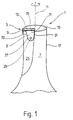
- FIG. 1 shows a perspective view of the head of a boring tool 1 with a knife plate 3, which is held in place by a clamping claw 5.
- the knife plate is here essentially rectangular, with its longitudinal edges 1 horizontally and therefore essentially perpendicular to the axis of rotation of the tool.
- the cutter insert 3 is arranged in a groove 9 which is made in the tool head 7 and which, or its longitudinal axis, runs in the radial direction with respect to the central and rotational axis 11 of the tool.
- the tool When a bore is machined, the tool is set in rotation, which is indicated by an arrow in FIG. 1, and introduced into the bore to be machined. It is also possible for the workpiece to rotate when the tool is stationary.
- FIG. 1 The perspective view according to FIG. 1 shows that the cutting edge 13 of the cutting tip 3 projects over the end face 15 of the boring tool 1. It can also be seen that - seen in the radial direction - the knife plate projects beyond the lateral surface 17 of the essentially cylindrical tool head 7.
- the clamping lip 21 of the clamping claw 5 rests on the front side of the knife plate 3, as seen in the direction of rotation, or on the knife chest 19 (FIG. 2).
- the surface 23 of the clamping claw 5 facing away from the knife breast 19 preferably ends flat with a boundary surface of the chip space 25.
- the clamping claw 5 is countersunk in a recess 27 made in the tool head 7, the contours of which are adapted to the outer shape of the clamping claw 5 in such a way that the latter has a positive fit is held in the tool head 7. It is held by means of a clamping screw 29 which penetrates the clamping claw 5 and engages in a thread in the tool head 7.
- the clamping claw 5 is shown in plan view, so that it can be seen that the lateral boundary edges 31 and 33 of the clamping lip 21 enclose an acute angle, which - viewed from the clamping screw - opens towards the front 35 of the clamping lip 21 .
- the rear side of the clamping claw 5 opposite the front side 35 is designed in the form of a circular arc, the radius of curvature of this area of the clamping claw being selected to be somewhat smaller than the associated, likewise circular-arcuate region of the recess 27.
- Figure 1 also shows that the right-hand limiting or Side edge 31 of the clamping claw runs practically parallel to the axis of rotation 11 of the boring tool 1.
- the chip space 25 is formed by a circular sector-shaped recess in the tool head 7.
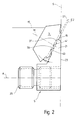
- FIG. 2 shows - greatly enlarged - a knife plate 3 and an associated clamping claw 5 in a side view.
- the remaining parts of the boring tool have been broken off or omitted here for the sake of clarity. Only the end face 15 of the tool head 7, over which the knife plate protrudes somewhat, is indicated by a line S. Knife plate 3 and clamp 5 are shown in the mounting position according to FIG. 1.
- the knife plate 3 has on its front side or on the knife breast 19 at least two, for example three grooves 37, each with projections 39 between them.
- the grooves are delimited by two associated flanks, which are arranged here in a V-shape at an angle of approximately 90 ° to one another.
- the angle of inclination of the flanks can be selected in a wide range and can also be, for example, 140 ° to 40 °, preferably 120 ° to 70 °.
- the side surfaces of the protrusions 39 are formed by the flanks of the adjacent grooves.
- a dashed line E1 is drawn through the deepest point of the grooves 37 and forms the imaginary contact plane of the knife plate 3.
- the contact surface of the clamping lip 21 of the clamping claw 5 facing the cutter plate 3 is correspondingly provided with grooves 41 and projections 43 lying between them.
- the flanks delimiting the grooves 41 are also arranged in a V-shape here and form an angle of approximately 90 °. For the angle enclosed by the flanks, what has been said for the flank angle of the grooves 37 made in the cutter plate 3 applies accordingly.
- the flanks of two adjacent grooves 41 form the side surfaces of the projection 43 arranged between these grooves.
- the projections 39 on the knife breast 19 and the projections 43 on the support surface of the clamping lip 21 are also substantially V-shaped in side view.
- the projections it is also possible for the projections to be rounded or flattened in the apex region, that is to say, as seen in section, to be quasi-trapezoidal.
- FIG. 2 An imaginary plane, the contact plane E2 of the clamping lip 21, runs through the deepest point of the grooves 41, shown in broken lines here.
- the two planes E1 and E2 preferably form an acute angle ⁇ , which, according to FIG seen from the direction of the clamping screw 29 (not shown here) ( Figure 1) opens.
- ⁇ an acute angle
- the clamping lip 21 initially rests with its front side 35 against the knife breast 19 and is finally pressed completely against the knife breast 19 during tightening.
- FIG. 2 that the contact plane E1 is pivoted with respect to the vertical S in FIG. 2 and thus with respect to the axis of rotation 11 of the boring tool 1 shown in FIG.
- the clamping claw 5 can be countersunk in the assembled state into the surface delimiting the chip space 25, so that the surface 23 of the clamping claw closes almost or completely flush with the surface delimiting the chip space.
- the chip discharge is only minimally impaired, so that chip evacuation is not impaired, particularly with small tool diameters.
- the knife plate 3 is pivoted in the tool 1 described here. This means that the front and back of the knife plate, which run parallel to one another, or their center plane, run at an angle to the center or axis of rotation of the tool. This enables the recessed arrangement of the clamping claw.
- This embodiment of the cutter plate 3 is a so-called indexable insert, the opposite longitudinal edges of which are both designed as cutting edges.
- the cutting tip 3 can be rotated through 180 ° about its central axis M which is perpendicular to the knife face 19, so that the cutting edge at the bottom in FIG. 2 replaces the cutting edge at the top in this illustration .
- Such a rotary movement of the indexable insert is only possible, while maintaining the desired anti-rotation properties, if the grooves 37 and the projections 39 lying between them are arranged symmetrically with respect to the longitudinal axis running in the knife breast 19.
- the projections on the knife chest are corresponding facing bearing surface of the clamping lip 21 is arranged.
- the inclination of the flanks of the grooves 37 and 41 or the projections 39 and 43 can - as stated above - be freely selected in a wide range. It is only essential that the design of the grooves 37 and protrusions 39 on the cutter plate 3 is coordinated with the design of the grooves 41 and protrusions 43 on the support surface of the clamping lip 21, so that there is an exact positive fit between the knife breast 19 and the clamping lip 21. Both flanks delimiting a groove interact with the two side surfaces of the projection which engages in this groove.
- the distance of the outer cutting edge from the center or rotation axis of the tool is determined by the arrangement of the grooves and projections both on the knife plate and on the clamping claw. It is therefore possible to manufacture different clamping claws which differ from one another in that the distances of the grooves and projections on the clamping claw which are measured from the axis A or from the front 35 are different. When using such different The distance between the outer cutting edge of the knife plate and the axis of rotation of the tool can be adjusted to a desired dimension. If, in deviation from FIG.
- the knife plate is not perpendicular to the axis of rotation of the tool, but is arranged essentially parallel to it, different tool diameters can be set in this way by presetting different distances of the active, outer cutting edge of the knife plate from the axis of rotation of the tool will.
- the different distances can be staggered by using different clamps of 5 ⁇ m, which means that the diameter of the holes to be machined can be varied in 5 ⁇ m steps.
- other gradations can also be carried out. In this way, the setting of a tool to a predetermined bore diameter is considerably simplified. A fine adjustment can thus be omitted, in particular if the gradation of the spacing of the grooves and projections on the clamping claw is selected to be fine enough.
- the arrangement of the clamping screw 29 within the clamping claw 5 can be seen from the side view according to FIG. It is indicated that the clamping screw 29 meshes with an external thread with an internal thread which is provided in a bore penetrating the clamping claw 5.
- the central axis A of the clamping screw is essentially perpendicular to that shown in FIG. 2 Vertical S, which runs in the surface delimiting the chip space 25.
- the knife insert 3 can be arranged displaceably within the recess or groove 9, that is to say, viewed in the radial direction, it can protrude more or less far beyond the lateral surface 17 of the tool head 7. If such an adjustability of the knife plate is desired, it is advantageous if the grooves on the knife breast 19 or on the support surface of the clamping lip 21 are continuous, because then a displacement of the knife plate radially outwards and inwards is not hindered. In addition, it must be ensured that the grooves and projections run in the direction of the displacement device. The form fit between the knife breast and the clamping lip results in guidance of the knife plate during this radial displacement. It is possible to provide suitable adjustment devices, for example set screws, in the tool head 7, with which the knife plate, as seen in the radial direction, is pressed outwards. For the sake of clarity, such adjustment screws are not shown here.
- the tool When machining bore surfaces, the tool is inserted into a bore with rotation.
- the front cutting edge 13 of the knife plate 3 removes chips from the bore wall.
- at least a portion of the outer edge of the knife plate seen in the radial direction which is approximately perpendicular in FIG. 1 and thus approximately parallel to the axis of rotation of the tool, can also remove 3 chips from the bore wall. Due to the removal of chips, forces act on the knife plate 3, which force them on the one hand against the rear boundary wall in FIG. 1, of the groove 9 receiving the knife plate.
- the positionally stable anchoring of the knife plate 3 is ensured in that the clamping claw 5 is arranged in the recess 27 in the tool head 7 and is thus secured against pivoting movement about the clamping screw 29. Because the right edge 31 of the clamping lip 21 runs practically parallel to the axis of rotation 11, the knife plate is held exactly in its radially innermost point. This results in a particularly long lever arm when anchoring the knife plate and when intercepting the forces acting against the direction of advance of the tool when machining a bore.
- the secure anchoring of the knife plate 3 in the tool head 7 is also maintained when the knife plate is displaced radially outwards. This results from the guiding properties of the grooves 37 and 41 and the projections 39 and 43.
- the clamping lip 21 is initially in the area when clamping the knife plate 3 the active cutting edge 13 is closest.
- the clamping lip 21 deforms somewhat, so that the grooves and projections located further down (see FIG. 1) on the contact surface of the clamping lip 21 engage with the corresponding grooves and projections on the knife face 19.
- a very high clamping force is introduced into the knife plate near the cutting edge 13, which is thus pressed against the wall of the groove 9 opposite the clamping lip and is thus securely clamped.
- an abutment for the knife plate at the base of the recess or groove 9 can be dispensed with.
- the cutter insert 3 can easily be designed as an indexable insert. The inactive cutting edge of the knife plate opposite the cutting edge 13 cannot be damaged even when the latter is clamped.
- the number of grooves and protrusions can be reduced to two grooves or protrusions. This means that the anti-rotation lock described here can also be used with very small knife inserts or with tools with a very small diameter. Even then there is a secure hold of the knife insert, even if it is displaced relatively far radially outward, so that the radially outermost edge of the knife insert extends far beyond the lateral surface 17 of the tool head 7.
- the knife plate together with the clamping claw can also be rotated by 90 °, so that the The outer cutting edge of the cutter insert runs essentially parallel to the axis of rotation of the tool.
- the knife plate is no longer adjustable in the radial direction.
- the tool can be set to a desired diameter by appropriate selection of suitable clamping claws. Otherwise, the knife plate can only be moved in the direction of the axis of rotation in this case, the anti-rotation device forming a guide in this direction.
Landscapes
- Engineering & Computer Science (AREA)
- Mechanical Engineering (AREA)
- Cutting Tools, Boring Holders, And Turrets (AREA)
- Drilling Tools (AREA)
- Drilling And Boring (AREA)
- Earth Drilling (AREA)
- Knives (AREA)
- Perforating, Stamping-Out Or Severing By Means Other Than Cutting (AREA)
- Details Of Cutting Devices (AREA)
- Polishing Bodies And Polishing Tools (AREA)
- Food-Manufacturing Devices (AREA)
- Auxiliary Devices For Machine Tools (AREA)
Applications Claiming Priority (2)
| Application Number | Priority Date | Filing Date | Title |
|---|---|---|---|
| DE4034345 | 1990-10-29 | ||
| DE4034345A DE4034345C1 (fr) | 1990-10-29 | 1990-10-29 |
Publications (3)
| Publication Number | Publication Date |
|---|---|
| EP0486791A2 true EP0486791A2 (fr) | 1992-05-27 |
| EP0486791A3 EP0486791A3 (en) | 1992-09-09 |
| EP0486791B1 EP0486791B1 (fr) | 1994-04-27 |
Family
ID=6417241
Family Applications (1)
| Application Number | Title | Priority Date | Filing Date |
|---|---|---|---|
| EP91116415A Expired - Lifetime EP0486791B1 (fr) | 1990-10-29 | 1991-09-26 | Outil à aléser |
Country Status (16)
| Country | Link |
|---|---|
| US (1) | US5211516A (fr) |
| EP (1) | EP0486791B1 (fr) |
| JP (1) | JP2756382B2 (fr) |
| KR (1) | KR970004869B1 (fr) |
| AT (1) | ATE104882T1 (fr) |
| AU (1) | AU647193B2 (fr) |
| BR (1) | BR9104661A (fr) |
| CA (1) | CA2053461C (fr) |
| CZ (1) | CZ278896B6 (fr) |
| DE (2) | DE4034345C1 (fr) |
| DK (1) | DK0486791T3 (fr) |
| ES (1) | ES2054417T3 (fr) |
| HU (1) | HU214606B (fr) |
| MX (1) | MX9101759A (fr) |
| PT (1) | PT99354B (fr) |
| RU (1) | RU2043882C1 (fr) |
Cited By (2)
| Publication number | Priority date | Publication date | Assignee | Title |
|---|---|---|---|---|
| EP0650792A3 (fr) * | 1993-10-01 | 1995-05-10 | OMUS S.p.A. in Amministrazione Straordinaria | Plaquette de coupe pour foret |
| WO1996017706A1 (fr) * | 1994-12-08 | 1996-06-13 | Seco Tools Ab | Outil et tete de coupe amovible pour l'usinage par enlevement de matiere |
Families Citing this family (20)
| Publication number | Priority date | Publication date | Assignee | Title |
|---|---|---|---|---|
| GB9304838D0 (en) * | 1993-03-09 | 1993-04-28 | Hydra Tools Int Plc | Rotary metal cutting tool |
| GB9418505D0 (en) * | 1994-09-14 | 1994-11-02 | C L A Tools Ltd | Boring tool and tool holder |
| WO1996014954A1 (fr) * | 1994-11-10 | 1996-05-23 | Kennametal Hertel Ag Werkzeuge + Hartstoffe | Outil de perçage |
| AT1323U1 (de) * | 1996-04-18 | 1997-03-25 | Plansee Tizit Gmbh | Schneidwerkzeug mit klemmvorrichtung |
| DE19654421B4 (de) * | 1996-12-24 | 2006-04-20 | MAPAL Fabrik für Präzisionswerkzeuge Dr. Kress KG | Messerplatte für ein Werkzeug zur spanabhebenden Feinbearbeitung |
| DE19721900C2 (de) * | 1997-05-26 | 1999-04-15 | Fette Wilhelm Gmbh | Schaftfräser |
| US6189584B1 (en) | 1998-08-12 | 2001-02-20 | Douglas Scott Cayce | Disposable carbide blade assembly for universal rotary cutter |
| IL127192A (en) * | 1998-11-22 | 2008-06-05 | Gideon Barazani | Resilient clamping mechanism for inserts |
| EP1213081B2 (fr) * | 2000-12-05 | 2012-03-14 | MAPAL Fabrik für Präzisionswerkzeuge Dr. Kress KG | Outil pour usinage de précision par enlèvement de copeaux |
| DE10113707C1 (de) * | 2001-03-16 | 2002-10-10 | Mapal Fab Praezision | Werkzeug zur spanabtragenden Bearbeitung eines Werkstücks aus hochfestem Material |
| GB0125690D0 (en) * | 2001-10-26 | 2001-12-19 | Bencere Elliott Ltd | A reamer and blade therefor |
| DE102005051545B4 (de) * | 2005-10-27 | 2008-01-31 | Kennametal Inc. | Werkzeughalter |
| JP4625424B2 (ja) * | 2006-05-17 | 2011-02-02 | 加藤電機株式会社 | ヒンジ装置及び携帯機器 |
| JP5338425B2 (ja) * | 2008-03-28 | 2013-11-13 | 三菱マテリアル株式会社 | インサート着脱式カッタ |
| DE102008063127A1 (de) * | 2008-12-24 | 2010-07-01 | Gühring Ohg | Werkzeug mit einem lösbar gespannten Schneidkörper |
| US9211590B2 (en) * | 2013-09-20 | 2015-12-15 | Kennametal Inc. | Screw head wedge clamp assembly for cutting tool |
| US9475138B2 (en) | 2014-01-22 | 2016-10-25 | Kennametal Inc. | Cutting tool having insert pocket with cantilevered member |
| DE202014003962U1 (de) * | 2014-05-13 | 2014-06-11 | Robert Bosch Gmbh | Werkzeug |
| US20160016233A1 (en) * | 2014-07-17 | 2016-01-21 | Kennametal India Limited | Notched cutting inserts and applications thereof |
| US20210205895A1 (en) * | 2018-05-24 | 2021-07-08 | No Screw Ltd. | Tool and cutting insert for internal cooling, and methos of manufacturing thereof |
Family Cites Families (13)
| Publication number | Priority date | Publication date | Assignee | Title |
|---|---|---|---|---|
| US2134140A (en) * | 1937-05-27 | 1938-10-25 | Frank P Miller | Inserted cutter blade and mounting therefor |
| US2382510A (en) * | 1943-07-26 | 1945-08-14 | Tungsten Carbide Tool Company | Boring tool |
| CA950651A (en) * | 1970-09-23 | 1974-07-09 | Dennis G. Jones | Cutting insert and clamping arrangement therefor |
| DE2614599C3 (de) * | 1976-04-05 | 1979-08-23 | Mapal Fabrik Fuer Praezisionswerkzeuge Dr. Kress Kg, 7080 Aalen | Reibahle für die Bearbeitung eng tolerierter Bohrungen |
| IT1145995B (it) * | 1981-01-08 | 1986-11-12 | Iscar Ltd | Utensile per il taglio di metalli provvisto di inserto sostituibile |
| US4414870A (en) * | 1981-02-19 | 1983-11-15 | Peterson Tool Company | Cutting tool |
| JPS57166747A (en) * | 1981-04-07 | 1982-10-14 | Toshiba Corp | Signal processing antenna |
| US4437802A (en) * | 1981-09-14 | 1984-03-20 | Hall Jr John J | Boring tool having a detachable cutting blade |
| DE3343448A1 (de) * | 1983-12-01 | 1985-06-13 | Hochmuth + Hollfelder, 8500 Nürnberg | Schneidwerkzeug zur spanabhebenden metallbearbeitung |
| US4645385A (en) * | 1984-03-23 | 1987-02-24 | Werner Keller | Device for clamping cutting inserts |
| JPH0833974B2 (ja) * | 1987-08-19 | 1996-03-29 | ソニー株式会社 | 磁気ヘッド駆動回路 |
| DE3742740C1 (de) * | 1987-12-07 | 1989-06-29 | Mapal Fab Praezision | Feinbohrwerkzeug |
| GB8811889D0 (en) * | 1988-05-19 | 1988-06-22 | Simmonds R L | Cutting tool |
-
1990
- 1990-10-29 DE DE4034345A patent/DE4034345C1/de not_active Expired - Fee Related
-
1991
- 1991-09-26 DE DE59101502T patent/DE59101502D1/de not_active Expired - Fee Related
- 1991-09-26 ES ES91116415T patent/ES2054417T3/es not_active Expired - Lifetime
- 1991-09-26 DK DK91116415.0T patent/DK0486791T3/da active
- 1991-09-26 EP EP91116415A patent/EP0486791B1/fr not_active Expired - Lifetime
- 1991-09-26 AT AT9191116415T patent/ATE104882T1/de not_active IP Right Cessation
- 1991-10-15 CA CA002053461A patent/CA2053461C/fr not_active Expired - Fee Related
- 1991-10-18 JP JP3270928A patent/JP2756382B2/ja not_active Expired - Fee Related
- 1991-10-22 US US07/780,250 patent/US5211516A/en not_active Expired - Lifetime
- 1991-10-25 MX MX9101759A patent/MX9101759A/es active IP Right Grant
- 1991-10-28 PT PT99354A patent/PT99354B/pt not_active IP Right Cessation
- 1991-10-28 KR KR1019910018955A patent/KR970004869B1/ko not_active Expired - Fee Related
- 1991-10-28 AU AU86761/91A patent/AU647193B2/en not_active Ceased
- 1991-10-28 BR BR919104661A patent/BR9104661A/pt not_active IP Right Cessation
- 1991-10-28 RU SU915001938A patent/RU2043882C1/ru not_active IP Right Cessation
- 1991-10-29 HU HU913393A patent/HU214606B/hu not_active IP Right Cessation
- 1991-10-29 CZ CS913276A patent/CZ278896B6/cs not_active IP Right Cessation
Cited By (2)
| Publication number | Priority date | Publication date | Assignee | Title |
|---|---|---|---|---|
| EP0650792A3 (fr) * | 1993-10-01 | 1995-05-10 | OMUS S.p.A. in Amministrazione Straordinaria | Plaquette de coupe pour foret |
| WO1996017706A1 (fr) * | 1994-12-08 | 1996-06-13 | Seco Tools Ab | Outil et tete de coupe amovible pour l'usinage par enlevement de matiere |
Also Published As
| Publication number | Publication date |
|---|---|
| HU214606B (hu) | 1998-04-28 |
| PT99354A (pt) | 1993-12-31 |
| ATE104882T1 (de) | 1994-05-15 |
| CZ278896B6 (en) | 1994-08-17 |
| HUH3691A (en) | 1993-12-28 |
| BR9104661A (pt) | 1992-06-16 |
| CA2053461A1 (fr) | 1992-04-30 |
| CS327691A3 (en) | 1992-05-13 |
| CA2053461C (fr) | 1998-05-19 |
| JP2756382B2 (ja) | 1998-05-25 |
| AU647193B2 (en) | 1994-03-17 |
| EP0486791B1 (fr) | 1994-04-27 |
| KR970004869B1 (ko) | 1997-04-08 |
| KR920007750A (ko) | 1992-05-27 |
| RU2043882C1 (ru) | 1995-09-20 |
| US5211516A (en) | 1993-05-18 |
| HU913393D0 (en) | 1992-01-28 |
| EP0486791A3 (en) | 1992-09-09 |
| AU8676191A (en) | 1992-05-07 |
| JPH05309511A (ja) | 1993-11-22 |
| DE59101502D1 (de) | 1994-06-01 |
| PT99354B (pt) | 1999-02-26 |
| MX9101759A (es) | 1992-06-05 |
| ES2054417T3 (es) | 1994-08-01 |
| DK0486791T3 (da) | 1994-09-12 |
| DE4034345C1 (fr) | 1991-08-29 |
Similar Documents
| Publication | Publication Date | Title |
|---|---|---|
| EP0486791B1 (fr) | Outil à aléser | |
| EP1136158B1 (fr) | Porte plaquette de coupe et plaquette du rainurage | |
| EP0674561B1 (fr) | Foret plein | |
| DE3832547C2 (fr) | ||
| DE2614599C3 (de) | Reibahle für die Bearbeitung eng tolerierter Bohrungen | |
| EP1213081B2 (fr) | Outil pour usinage de précision par enlèvement de copeaux | |
| DE2615609A1 (de) | Fraeswerkzeug | |
| DD293522A5 (de) | Entgratwerkzeug mit schneidmesser | |
| DE29508112U1 (de) | Profilmesserkopf | |
| DE10132721C1 (de) | Schneidvorrichtung | |
| EP0381924B1 (fr) | Alésoir | |
| EP0673700B1 (fr) | Alésoir | |
| DE2741388A1 (de) | Stirnmesserkopf zum verzahnen von zahnraedern | |
| EP3741483A1 (fr) | Plaquette de coupe, porte-plaquette et dispositif de coupe | |
| EP2895289B1 (fr) | Outil d'usinage de pièces par enlèvement de matière | |
| EP2200775B1 (fr) | Alésoir | |
| EP0261465B1 (fr) | Outil de fraisage des filetages | |
| EP2197615B1 (fr) | Alésoir | |
| EP0144073A2 (fr) | Outil de coupe | |
| DE2755279C2 (fr) | ||
| EP1027186B1 (fr) | Outil pour l'usinage fin de surfaces d'alesages | |
| DE102007048634B4 (de) | Reibahle | |
| DE2915616C2 (fr) | ||
| CH673245A5 (fr) | ||
| DE102007048633B3 (de) | Reibahle |
Legal Events
| Date | Code | Title | Description |
|---|---|---|---|
| PUAI | Public reference made under article 153(3) epc to a published international application that has entered the european phase |
Free format text: ORIGINAL CODE: 0009012 |
|
| AK | Designated contracting states |
Kind code of ref document: A2 Designated state(s): AT BE CH DE DK ES FR GB IT LI NL SE |
|
| PUAL | Search report despatched |
Free format text: ORIGINAL CODE: 0009013 |
|
| AK | Designated contracting states |
Kind code of ref document: A3 Designated state(s): AT BE CH DE DK ES FR GB IT LI NL SE |
|
| 17P | Request for examination filed |
Effective date: 19920729 |
|
| 17Q | First examination report despatched |
Effective date: 19930601 |
|
| GRAA | (expected) grant |
Free format text: ORIGINAL CODE: 0009210 |
|
| AK | Designated contracting states |
Kind code of ref document: B1 Designated state(s): AT BE CH DE DK ES FR GB IT LI NL SE |
|
| REF | Corresponds to: |
Ref document number: 104882 Country of ref document: AT Date of ref document: 19940515 Kind code of ref document: T |
|
| REF | Corresponds to: |
Ref document number: 59101502 Country of ref document: DE Date of ref document: 19940601 |
|
| ITF | It: translation for a ep patent filed | ||
| ET | Fr: translation filed | ||
| REG | Reference to a national code |
Ref country code: ES Ref legal event code: FG2A Ref document number: 2054417 Country of ref document: ES Kind code of ref document: T3 |
|
| GBT | Gb: translation of ep patent filed (gb section 77(6)(a)/1977) |
Effective date: 19940630 |
|
| REG | Reference to a national code |
Ref country code: DK Ref legal event code: T3 |
|
| EAL | Se: european patent in force in sweden |
Ref document number: 91116415.0 |
|
| PLBE | No opposition filed within time limit |
Free format text: ORIGINAL CODE: 0009261 |
|
| STAA | Information on the status of an ep patent application or granted ep patent |
Free format text: STATUS: NO OPPOSITION FILED WITHIN TIME LIMIT |
|
| 26N | No opposition filed | ||
| REG | Reference to a national code |
Ref country code: GB Ref legal event code: IF02 |
|
| PGFP | Annual fee paid to national office [announced via postgrant information from national office to epo] |
Ref country code: AT Payment date: 20050908 Year of fee payment: 15 |
|
| PGFP | Annual fee paid to national office [announced via postgrant information from national office to epo] |
Ref country code: DK Payment date: 20050913 Year of fee payment: 15 |
|
| PGFP | Annual fee paid to national office [announced via postgrant information from national office to epo] |
Ref country code: NL Payment date: 20050914 Year of fee payment: 15 |
|
| PGFP | Annual fee paid to national office [announced via postgrant information from national office to epo] |
Ref country code: CH Payment date: 20050916 Year of fee payment: 15 |
|
| PGFP | Annual fee paid to national office [announced via postgrant information from national office to epo] |
Ref country code: BE Payment date: 20051014 Year of fee payment: 15 |
|
| PG25 | Lapsed in a contracting state [announced via postgrant information from national office to epo] |
Ref country code: AT Free format text: LAPSE BECAUSE OF NON-PAYMENT OF DUE FEES Effective date: 20060926 |
|
| PG25 | Lapsed in a contracting state [announced via postgrant information from national office to epo] |
Ref country code: CH Free format text: LAPSE BECAUSE OF NON-PAYMENT OF DUE FEES Effective date: 20060930 Ref country code: BE Free format text: LAPSE BECAUSE OF NON-PAYMENT OF DUE FEES Effective date: 20060930 Ref country code: LI Free format text: LAPSE BECAUSE OF NON-PAYMENT OF DUE FEES Effective date: 20060930 |
|
| PG25 | Lapsed in a contracting state [announced via postgrant information from national office to epo] |
Ref country code: DK Free format text: LAPSE BECAUSE OF NON-PAYMENT OF DUE FEES Effective date: 20061002 |
|
| PG25 | Lapsed in a contracting state [announced via postgrant information from national office to epo] |
Ref country code: NL Free format text: LAPSE BECAUSE OF NON-PAYMENT OF DUE FEES Effective date: 20070401 |
|
| REG | Reference to a national code |
Ref country code: DK Ref legal event code: EBP |
|
| REG | Reference to a national code |
Ref country code: CH Ref legal event code: PL |
|
| NLV4 | Nl: lapsed or anulled due to non-payment of the annual fee |
Effective date: 20070401 |
|
| BERE | Be: lapsed |
Owner name: MAPAL FABRIK FUR PRAZISIONSWERKZEUGE DR. *KRESS K. Effective date: 20060930 |
|
| PGFP | Annual fee paid to national office [announced via postgrant information from national office to epo] |
Ref country code: ES Payment date: 20080922 Year of fee payment: 18 |
|
| PGFP | Annual fee paid to national office [announced via postgrant information from national office to epo] |
Ref country code: FR Payment date: 20080811 Year of fee payment: 18 Ref country code: IT Payment date: 20080814 Year of fee payment: 18 |
|
| PGFP | Annual fee paid to national office [announced via postgrant information from national office to epo] |
Ref country code: GB Payment date: 20080822 Year of fee payment: 18 |
|
| PGFP | Annual fee paid to national office [announced via postgrant information from national office to epo] |
Ref country code: DE Payment date: 20081001 Year of fee payment: 18 |
|
| PGFP | Annual fee paid to national office [announced via postgrant information from national office to epo] |
Ref country code: SE Payment date: 20080818 Year of fee payment: 18 |
|
| EUG | Se: european patent has lapsed | ||
| GBPC | Gb: european patent ceased through non-payment of renewal fee |
Effective date: 20090926 |
|
| REG | Reference to a national code |
Ref country code: FR Ref legal event code: ST Effective date: 20100531 |
|
| PG25 | Lapsed in a contracting state [announced via postgrant information from national office to epo] |
Ref country code: DE Free format text: LAPSE BECAUSE OF NON-PAYMENT OF DUE FEES Effective date: 20100401 Ref country code: FR Free format text: LAPSE BECAUSE OF NON-PAYMENT OF DUE FEES Effective date: 20090930 |
|
| PG25 | Lapsed in a contracting state [announced via postgrant information from national office to epo] |
Ref country code: GB Free format text: LAPSE BECAUSE OF NON-PAYMENT OF DUE FEES Effective date: 20090926 |
|
| PG25 | Lapsed in a contracting state [announced via postgrant information from national office to epo] |
Ref country code: IT Free format text: LAPSE BECAUSE OF NON-PAYMENT OF DUE FEES Effective date: 20090926 |
|
| PG25 | Lapsed in a contracting state [announced via postgrant information from national office to epo] |
Ref country code: SE Free format text: LAPSE BECAUSE OF NON-PAYMENT OF DUE FEES Effective date: 20090927 |
|
| REG | Reference to a national code |
Ref country code: ES Ref legal event code: FD2A Effective date: 20110708 |
|
| PG25 | Lapsed in a contracting state [announced via postgrant information from national office to epo] |
Ref country code: ES Free format text: LAPSE BECAUSE OF NON-PAYMENT OF DUE FEES Effective date: 20110628 |
|
| PG25 | Lapsed in a contracting state [announced via postgrant information from national office to epo] |
Ref country code: ES Free format text: LAPSE BECAUSE OF NON-PAYMENT OF DUE FEES Effective date: 20090927 |