EP0486844A1 - Wagenheber - Google Patents
Wagenheber Download PDFInfo
- Publication number
- EP0486844A1 EP0486844A1 EP91118292A EP91118292A EP0486844A1 EP 0486844 A1 EP0486844 A1 EP 0486844A1 EP 91118292 A EP91118292 A EP 91118292A EP 91118292 A EP91118292 A EP 91118292A EP 0486844 A1 EP0486844 A1 EP 0486844A1
- Authority
- EP
- European Patent Office
- Prior art keywords
- vehicle jack
- supporting leg
- support
- jack
- support arm
- Prior art date
- Legal status (The legal status is an assumption and is not a legal conclusion. Google has not performed a legal analysis and makes no representation as to the accuracy of the status listed.)
- Granted
Links
Images


Classifications
-
- B—PERFORMING OPERATIONS; TRANSPORTING
- B66—HOISTING; LIFTING; HAULING
- B66F—HOISTING, LIFTING, HAULING OR PUSHING, NOT OTHERWISE PROVIDED FOR, e.g. DEVICES WHICH APPLY A LIFTING OR PUSHING FORCE DIRECTLY TO THE SURFACE OF A LOAD
- B66F3/00—Devices, e.g. jacks, adapted for uninterrupted lifting of loads
- B66F3/08—Devices, e.g. jacks, adapted for uninterrupted lifting of loads screw operated
- B66F3/12—Devices, e.g. jacks, adapted for uninterrupted lifting of loads screw operated comprising toggle levers
Definitions
- the invention relates to a jack according to the preamble of claim 1.
- Car jacks of this type are required in order to be able to lift cars in the event of a breakdown, for example to replace a defective wheel with the spare wheel.
- DE-AS 24 44 132 shows such a jack with a supporting leg and a support arm movably fastened about a horizontal pivot axis, which are pivoted against one another as a moving element via a threaded spindle connected directly to them.
- the pillar and support arm are pressed metal parts with a U-shaped cross-section.
- the side bars of the profiles for the support leg and support arm are at right angles, almost connected to the bottom of the profile with a sharp edge.
- the disadvantage of a jack of the prescribed design results in a high weight for a part that is only required in special exceptional cases and must otherwise be moved as ballast with the vehicle.
- the jack has a lower weight with the same load capacity. In addition, it requires less storage space in the vehicle.
- the jack has a support leg 1 with an attachment foot 2 arranged at its lower end.
- a support arm 4 is rotatably connected to the support leg 1 via a horizontal pivot axis 3. It has a support plate 5 at its upper end.
- a movement element 8 is connected directly to the support arm 4 and the supporting leg 1.
- the movement element 8 is designed as a threaded spindle 9 which interacts with a nut in the articulation point 7 on the supporting leg 1.
- a hand crank 10 serves to rotate the threaded spindle 9.
- the foot 2 stands on the floor 11, and the support arm 4 engages with its support plate 5 under the vehicle 12 to be lifted.
- Fig. 2 shows a further embodiment of the jack according to the invention. It in turn consists of a pillar 1 with a base 2 and a support frame 4 with a support plate 5, which are connected to one another in a rotatable manner via a horizontal pivot axis 3.
- a parallelogram linkage consisting of two parallelogram arms 15, 16, is connected to the support arm 4 and the base 2 via two articulation points.
- the movement element is at the break point 17, which connects the parallelogram arms 15, 16 and is connected to the pivot axis 3.
- the movement element in turn consists of a threaded spindle 9 with a hand crank 10 which, via a movement nut, in this case arranged in the pivot axis 3, effects the adjustment of the jack.
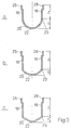
- Fig. 3 shows three different cross sections through the profile of the main leg 1.
- the profiles are composed of two side webs 18, 19 and a bottom 20.
- the bottom is convex in all cases.
- the distance 21 from the center 22 of the base 20 to the transition 23 between the side webs 18, 19 and the base 20 is at least 20% of the width 24 of the side webs 18, 19.
- To stiffen the side webs they each have a stiffening bead 25, 26 at the upper edge.
- the bottom shape of the profile cross sections is semicircular in example a, curved in example b and roof-shaped in example c, the saddle point of the roof being flattened.
Landscapes
- Life Sciences & Earth Sciences (AREA)
- Engineering & Computer Science (AREA)
- Geology (AREA)
- Mechanical Engineering (AREA)
- Structural Engineering (AREA)
- Vehicle Cleaning, Maintenance, Repair, Refitting, And Outriggers (AREA)
- Manipulator (AREA)
- Fittings On The Vehicle Exterior For Carrying Loads, And Devices For Holding Or Mounting Articles (AREA)
Abstract
Description
- Die Erfindung betrifft einen Wagenheber nach dem Oberbegriff des Anspruchs 1.
- Derartige Wagenheber werden benötigt, um vorzugsweise Pkw im Falle einer Panne anheben zu können, um beispielsweise ein defektes Rad gegen das Reserverad auszutauschen.
- Die DE-AS 24 44 132 zeigt einen derartigen Wagenheber mit einem Standbein und einem um eine horizontale Schwenkachse beweglich befestigten Tragarm, die über eine direkt mit ihnen verbundene Gewindespindel als Bewegungselement gegeneinander verschwenkt werden. Bei diesem Wagenheber sind Standbein und Tragarm Metallpreßteile mit U-förmigem Querschnitt. Die Seitenstege der Profile für Standbein und Tragarm sind rechtwinklig, nahezu über eine scharfe Kante mit dem Boden des Profils verbunden. Nachteilig bei einem Wagenheber der vorgeschriebenen Ausbildungsform ergibt sich ein hohes Gewicht für ein Teil, das nur in besonderen Ausnahmefällen benötigt wird und ansonsten als Ballast mit dem Fahrzeug bewegt werden muß.
- Von daher stellt sich die Aufgabe, einen Wagenheber der vorbeschriebenen Ausbildungsform derartig weiterzubilden, daß er ein geringeres Gewicht erhält.
- Diese Aufgabe wird erfindungsgemäß durch die Merkmale des Anspruchs 1 gelöst. Vorteilhafte Welterbildungen sind in den Ansprüchen 2 und 3 beschrieben.
- Die mit der Erfindung erzielten Vorteile bestehen insbesondere darin, daß der Wagenheber bei gleicher Tragfähigkeit ein geringeres Gewicht hat. Darüber hinaus benötigt er weniger Stauraum im Fahrzeug.
- Ein Ausführungsbeispiel der Erfindung ist in der Zeichnung dargestellt und wird im folgenden näher beschrieben. Es zeigen
- Fig. 1
- einen Einarmwagenheber, bei dem das Bewegungselement direkt mit dem Standbein und dem Tragarm verbunden ist,
- Fig. 2
- einen derartigen Wagenheber, bei dem das Bewegungselement an einer Seite über ein Parallelogrammgestänge mit dem Standbein und dem Tragarm verbunden ist, und
- Fig. 3
- einen Schnitt durch drei verschiedene Profile für das Standbein.
- Der Wagenheber weist ein Standbein 1 mit einem an seinem unteren Ende angeordneten Aufsetzfuß 2 auf. Über eine horizontale Schwenkachse 3 ist ein Tragarm 4 drehbeweglich mit dem Standbein 1 verbunden. Er weist an seinem oberen Ende eine Tragplatte 5 auf. An Anlenkpunkten 6, 7 ist ein Bewegungselement 8 direkt mit dem Tragarm 4 und dem Standbein 1 verbunden. Im Ausführungsbeispiel ist das Bewegungselement 8 als Gewindespindel 9 ausgebildet, das mit einer Mutter im Anlenkpunkt 7 am Standbein 1 zusammenwirkt. Eine Handkurbel 10 dient zum Drehen der Gewindespindel 9. Der Aufsetzfuß 2 steht auf dem Boden 11 auf, und der Tragarm 4 greift mit seiner Tragplatte 5 unter das zu hebende Fahrzeug 12.
- Fig. 2 zeigt eine weitere Ausbildungsform des erfindungsgemäßen Wagenhebers. Er besteht wiederum aus Standbein 1 mit Aufsetzfuß 2 und Tragrahmen 4 mit Tragplatte 5, die über eine horizontale Schwenkachse 3 drehbeweglich miteinander verbunden sind. Über zwei Gelenkpunkte ist ein Parallelogrammgestänge, bestehend aus zwei Parallelogrammarmen 15, 16, mit dem Tragarm 4 und dem Aufsetzfuß 2 verbunden. Bei diesem Wagenheber ist das Bewegungselement am Knickpunkt 17, der die Parallelogrammarme 15, 16 verbindet und an der Schwenkachse 3 angebunden. Das Bewegungselement besteht wiederum aus einer Gewindespindel 9 mit einer Handkurbel 10, die über eine Bewegungsmutter, in diesem Fall in der Schwenkachse 3 angeordnet, die Verstellung des Wagenhebers bewirkt.
- Fig. 3 zeigt drei verschiedene Querschnitte durch das Profil des Standbeins 1. Die Profile setzen sich aus zwei Seitenstegen 18, 19 und einem Boden 20 zusammen. Der Boden ist in allen Fällen konvex ausgebildet. Der Abstand 21 von Mitte 22 des Bodens 20 zum Übergang 23 zwischen Seitenstegen 18, 19 und Boden 20 beträgt wenigstens 20 % der Breite 24 der Seitenstege 18, 19. Zur Versteifung der Seitenstege weisen diese am oberen Rand jeweils eine Versteifungssicke 25, 26 auf. Die Bodenform der Profilquerschnitte ist im Beispiel a halbrund, im Beispiel b gewölbt und im Beispiel c dachförmig, wobei der Sattelpunkt des Daches abgeplattet ist, ausgebildet.
-
- 1.
- Standbein
- 2.
- Aufsetzfuß
- 3.
- Schwenkachse
- 4.
- Tragarm
- 5.
- Tragplatte
- 6.
- Anlenkpunkt
- 7.
- Anlenkpunkt
- 8.
- Bewegungselement
- 9.
- Gewindespindel
- 10.
- Handkurbel
- 11.
- Boden
- 12.
- Fahrzeug
- 13.
- Gelenkpunkt
- 14.
- Gelenkpunkt
- 15.
- Parallelogrammarm
- 16.
- Parallelogrammarm
- 17.
- Knickpunkt
- 18.
- Seitensteg
- 19.
- Seitensteg
- 20.
- Boden
- 21.
- Abstand
- 22.
- Mitte
- 23.
- Übergang
- 24.
- Breite
- 25.
- Sicke
- 26.
- Sicke
Claims (3)
- Wagenheber mit einem, einen Aufsetzfuß aufweisenden Standbein, dessen Querschnitt U-förmig ausgebildet ist, einem daran um eine festgelegte horizontale Schwenkachse beweglich befestigten Tragarm und einem direkt oder über ein Parallelogramm- oder Scherengestänge mit dem Standbein und dem Tragarm verbundenes Bewegungselement, dadurch gekennzeichnet, daß der mit zwei Seitenstegen (18, 19) verbundene Boden (20) des Standbeinprofils konvex ausgebildet ist.
- Wagenheber nach Anspruch 1, dadurch gekennzeichnet, daß die Mitte (22) des Bodens (20) des Standbeinprofils den Übergang (23) von den Seitenstegen (18, 19) zum Boden (20) um wenigstens 20 % der Breite (24) der Seitenstege (18, 19) überragt.
- Wagenheber nach Anspruch 1 oder Anspruch 2, dadurch gekennzeichnet, daß der Boden (20) des Standbeinprofils nur an einzelnen Abschnitten der Gesamtlänge des Standbeins konvex ausgebildet ist.
Applications Claiming Priority (2)
| Application Number | Priority Date | Filing Date | Title |
|---|---|---|---|
| DE9015832U | 1990-11-20 | ||
| DE9015832U DE9015832U1 (de) | 1990-11-20 | 1990-11-20 | Wagenheber |
Publications (2)
| Publication Number | Publication Date |
|---|---|
| EP0486844A1 true EP0486844A1 (de) | 1992-05-27 |
| EP0486844B1 EP0486844B1 (de) | 1994-07-27 |
Family
ID=6859525
Family Applications (1)
| Application Number | Title | Priority Date | Filing Date |
|---|---|---|---|
| EP91118292A Revoked EP0486844B1 (de) | 1990-11-20 | 1991-10-26 | Wagenheber |
Country Status (10)
| Country | Link |
|---|---|
| US (1) | US5275378A (de) |
| EP (1) | EP0486844B1 (de) |
| JP (1) | JPH04266398A (de) |
| BR (1) | BR9104828A (de) |
| CS (1) | CS348491A3 (de) |
| DE (2) | DE9015832U1 (de) |
| ES (1) | ES2031801T3 (de) |
| MX (1) | MX9102114A (de) |
| PT (1) | PT8395U (de) |
| ZA (1) | ZA918490B (de) |
Families Citing this family (17)
| Publication number | Priority date | Publication date | Assignee | Title |
|---|---|---|---|---|
| ES1024192Y (es) * | 1993-03-30 | 1994-04-16 | Tub Sa | Dispositivo estabilizador automatico y de refuerzo para gatos elevadores. |
| DE4314136C2 (de) * | 1993-04-30 | 1995-05-24 | Bilstein August Gmbh Co Kg | Wagenheber |
| ES2129311B1 (es) * | 1996-01-22 | 2000-05-01 | Batz S Coop Ltada | Gato para vehiculos. |
| ES2129310B1 (es) * | 1996-01-22 | 2000-02-01 | Batz S Coop Ltda | Gato para vehiculos. |
| AR005772A1 (es) * | 1996-02-14 | 1999-07-14 | Ventra Group Inc | Gato |
| ES2130961B1 (es) * | 1996-09-27 | 2000-03-01 | Batz S Coop Ltda | Gato para vehiculos. |
| FR2758806B1 (fr) * | 1997-01-24 | 1999-04-16 | Adwest Bowden France Sa | Cric pour soulever un vehicule |
| DE19804334C2 (de) * | 1998-02-05 | 2003-05-28 | Thyssen Krupp Bilstein Gmbh | Wagenheber |
| US6527251B1 (en) * | 1998-11-24 | 2003-03-04 | Norco Industries, Inc. | Jack with urethane brake |
| ES2181510B1 (es) * | 1999-05-17 | 2004-06-01 | Batz, S.Coop. | Gato elevacoches. |
| US6634688B2 (en) | 2001-10-26 | 2003-10-21 | Ventra Group Inc. | Method for mounting a vehicle jack on a motor vehicle |
| US7938348B2 (en) * | 2004-07-27 | 2011-05-10 | Owens Corning Intellectual Capital, Llc | Loosefill blowing machine with a chute |
| US8016266B2 (en) * | 2006-12-04 | 2011-09-13 | Bogert Richard W | Portable apparatus and method for lifting a vehicle that compensates for lateral motion of the vehicle |
| US8628062B2 (en) * | 2007-05-04 | 2014-01-14 | Raju Alluru | Vehicle jack assembly |
| US8141851B2 (en) * | 2007-06-04 | 2012-03-27 | Boytcho Manev | Portable vehicle lift |
| US8585017B2 (en) | 2009-11-30 | 2013-11-19 | Norco Industries, Inc. | Low profile scissor jack |
| US9108830B2 (en) | 2013-08-01 | 2015-08-18 | A & A Attachments, Llc | Secure connection load-rest for a ground-engaging vehicle jack |
Citations (3)
| Publication number | Priority date | Publication date | Assignee | Title |
|---|---|---|---|---|
| US2435693A (en) * | 1941-05-15 | 1948-02-10 | Hancock Mfg Company | Vehicle jack |
| DE2444132A1 (de) * | 1974-05-04 | 1975-11-13 | Metallifacture Ltd | Hebevorrichtung, insbesondere wagenheber |
| GB1551257A (en) * | 1976-12-31 | 1979-08-30 | Lake & Elliot Jacks & Equipmen | Scissors jack |
Family Cites Families (7)
| Publication number | Priority date | Publication date | Assignee | Title |
|---|---|---|---|---|
| AT358769B (de) * | 1974-06-07 | 1980-09-25 | Bilstein August Fa | Wagenheber |
| DE2625085A1 (de) * | 1976-06-04 | 1977-12-08 | Bilstein August Fa | Wagenheber |
| GB1551256A (en) * | 1976-12-31 | 1979-08-30 | Lake & Elliot Jacks & Equipmen | Scissors jack |
| DE2851980C2 (de) * | 1978-12-01 | 1982-07-01 | E.A. Storz Gmbh & Co Kg, 7200 Tuttlingen | Wagenheber |
| US4475373A (en) * | 1982-03-18 | 1984-10-09 | Ikenberry Maynard D | Hydraulic powered pipe and tubing straightener |
| DE3664900D1 (en) * | 1985-05-10 | 1989-09-14 | Bilstein August Gmbh Co Kg | Jack |
| JPS6376792U (de) * | 1986-11-04 | 1988-05-21 |
-
1990
- 1990-11-20 DE DE9015832U patent/DE9015832U1/de not_active Expired - Lifetime
-
1991
- 1991-10-24 ZA ZA918490A patent/ZA918490B/xx unknown
- 1991-10-26 ES ES91118292T patent/ES2031801T3/es not_active Expired - Lifetime
- 1991-10-26 DE DE59102351T patent/DE59102351D1/de not_active Revoked
- 1991-10-26 EP EP91118292A patent/EP0486844B1/de not_active Revoked
- 1991-11-06 BR BR919104828A patent/BR9104828A/pt not_active IP Right Cessation
- 1991-11-08 US US07/790,226 patent/US5275378A/en not_active Expired - Fee Related
- 1991-11-18 CS CS913484A patent/CS348491A3/cs unknown
- 1991-11-18 MX MX9102114A patent/MX9102114A/es not_active IP Right Cessation
- 1991-11-19 PT PT8395U patent/PT8395U/pt not_active IP Right Cessation
- 1991-11-19 JP JP3303036A patent/JPH04266398A/ja active Pending
Patent Citations (3)
| Publication number | Priority date | Publication date | Assignee | Title |
|---|---|---|---|---|
| US2435693A (en) * | 1941-05-15 | 1948-02-10 | Hancock Mfg Company | Vehicle jack |
| DE2444132A1 (de) * | 1974-05-04 | 1975-11-13 | Metallifacture Ltd | Hebevorrichtung, insbesondere wagenheber |
| GB1551257A (en) * | 1976-12-31 | 1979-08-30 | Lake & Elliot Jacks & Equipmen | Scissors jack |
Also Published As
| Publication number | Publication date |
|---|---|
| EP0486844B1 (de) | 1994-07-27 |
| JPH04266398A (ja) | 1992-09-22 |
| DE9015832U1 (de) | 1991-02-07 |
| DE59102351D1 (de) | 1994-09-01 |
| ES2031801T3 (es) | 1994-10-16 |
| ZA918490B (en) | 1992-07-29 |
| CS348491A3 (en) | 1992-06-17 |
| ES2031801T1 (es) | 1993-01-01 |
| MX9102114A (es) | 1992-06-01 |
| BR9104828A (pt) | 1992-06-23 |
| PT8395T (pt) | 1992-05-29 |
| PT8395U (pt) | 1994-09-30 |
| US5275378A (en) | 1994-01-04 |
Similar Documents
| Publication | Publication Date | Title |
|---|---|---|
| EP0486844B1 (de) | Wagenheber | |
| DE10022600A1 (de) | Teleskopkran | |
| EP0221911B1 (de) | Wagenheber | |
| DE2658250A1 (de) | Fahrbarer und hebbarer arbeitskorb | |
| DE2208777B2 (de) | Scherenhebetisch | |
| EP0785903B1 (de) | Hub-dreh-vorrichtung zur aufnahme eines kraftfahrzeuges | |
| DE2944289A1 (de) | Hebefahrzeug | |
| DE3305384A1 (de) | Einrichtung zur inspektion der unterseite von bruecken | |
| DE19615592A1 (de) | Hubwagen mit einem anhebbaren Lastrahmen | |
| EP0749936B1 (de) | Wagenheber | |
| DE2058592A1 (de) | Auf einem Fahrzeug angeordneter Gelenkmast mit Arbeitskorb | |
| EP0523400B1 (de) | Zusammenschiebbares Verdeck für Fahrzeuge oder Fahrzeugaufbauten | |
| EP0802075A2 (de) | Hilfsrahmen | |
| DE19530369C2 (de) | Vorrichtung zum Heben von Kraftfahrzeugen | |
| DE2902579C2 (de) | Wagenheber | |
| EP2019014A2 (de) | Hubwagen | |
| DE2856350A1 (de) | Fahrzeug zum transport von coils | |
| EP1186233A2 (de) | Spritzgestängeführung | |
| EP0622328A2 (de) | Wagenheber | |
| DE3010483A1 (de) | Hintere abstuetzzylinder bei einem transportfahrzeug | |
| DE2901786A1 (de) | Selbstfahrende arbeitsbuehne | |
| DE1580050B2 (de) | Lastfahrzeug-laderampe mit hubvorrichtung | |
| DE2717351C2 (de) | Ladebordwand für Lastkraftwagen | |
| DE3815307A1 (de) | Fahrzeug zum transport von stirnseitig offenen stahlbeton-raumzellen, z.b. fertiggaragen | |
| DE3026110C2 (de) |
Legal Events
| Date | Code | Title | Description |
|---|---|---|---|
| PUAI | Public reference made under article 153(3) epc to a published international application that has entered the european phase |
Free format text: ORIGINAL CODE: 0009012 |
|
| AK | Designated contracting states |
Kind code of ref document: A1 Designated state(s): BE DE ES FR GB IT SE |
|
| 17P | Request for examination filed |
Effective date: 19920424 |
|
| GBC | Gb: translation of claims filed (gb section 78(7)/1977) | ||
| EL | Fr: translation of claims filed | ||
| ITCL | It: translation for ep claims filed |
Representative=s name: RICCARDI SERGIO & CO. |
|
| 17Q | First examination report despatched |
Effective date: 19920813 |
|
| GRAA | (expected) grant |
Free format text: ORIGINAL CODE: 0009210 |
|
| AK | Designated contracting states |
Kind code of ref document: B1 Designated state(s): BE DE ES FR GB IT SE |
|
| PG25 | Lapsed in a contracting state [announced via postgrant information from national office to epo] |
Ref country code: FR Effective date: 19940727 |
|
| REF | Corresponds to: |
Ref document number: 59102351 Country of ref document: DE Date of ref document: 19940901 |
|
| PGFP | Annual fee paid to national office [announced via postgrant information from national office to epo] |
Ref country code: DE Payment date: 19940914 Year of fee payment: 4 |
|
| PGFP | Annual fee paid to national office [announced via postgrant information from national office to epo] |
Ref country code: BE Payment date: 19940916 Year of fee payment: 4 |
|
| PGFP | Annual fee paid to national office [announced via postgrant information from national office to epo] |
Ref country code: SE Payment date: 19940919 Year of fee payment: 4 Ref country code: FR Payment date: 19940919 Year of fee payment: 4 |
|
| GBT | Gb: translation of ep patent filed (gb section 77(6)(a)/1977) |
Effective date: 19940824 |
|
| ITF | It: translation for a ep patent filed | ||
| REG | Reference to a national code |
Ref country code: ES Ref legal event code: FG2A Ref document number: 2031801 Country of ref document: ES Kind code of ref document: T3 |
|
| PGFP | Annual fee paid to national office [announced via postgrant information from national office to epo] |
Ref country code: ES Payment date: 19941020 Year of fee payment: 4 |
|
| EN | Fr: translation not filed | ||
| EAL | Se: european patent in force in sweden |
Ref document number: 91118292.1 |
|
| PLBI | Opposition filed |
Free format text: ORIGINAL CODE: 0009260 |
|
| 26 | Opposition filed |
Opponent name: METALLIFACTURE LIMITED Effective date: 19950316 |
|
| RDAG | Patent revoked |
Free format text: ORIGINAL CODE: 0009271 |
|
| STAA | Information on the status of an ep patent application or granted ep patent |
Free format text: STATUS: PATENT REVOKED |
|
| 27W | Patent revoked |
Effective date: 19950703 |
|
| GBPR | Gb: patent revoked under art. 102 of the ep convention designating the uk as contracting state |
Free format text: 950703 |