EP0486848A1 - Capteur de position ou de vitesse relative entre un cylindre d'amortisseur et un piston se déplaçant dans ce cylindre - Google Patents
Capteur de position ou de vitesse relative entre un cylindre d'amortisseur et un piston se déplaçant dans ce cylindre Download PDFInfo
- Publication number
- EP0486848A1 EP0486848A1 EP91118384A EP91118384A EP0486848A1 EP 0486848 A1 EP0486848 A1 EP 0486848A1 EP 91118384 A EP91118384 A EP 91118384A EP 91118384 A EP91118384 A EP 91118384A EP 0486848 A1 EP0486848 A1 EP 0486848A1
- Authority
- EP
- European Patent Office
- Prior art keywords
- sensor
- winding
- permanent magnet
- piston rod
- sensor according
- Prior art date
- Legal status (The legal status is an assumption and is not a legal conclusion. Google has not performed a legal analysis and makes no representation as to the accuracy of the status listed.)
- Granted
Links
Images




Classifications
-
- G—PHYSICS
- G01—MEASURING; TESTING
- G01P—MEASURING LINEAR OR ANGULAR SPEED, ACCELERATION, DECELERATION, OR SHOCK; INDICATING PRESENCE, ABSENCE, OR DIRECTION, OF MOVEMENT
- G01P3/00—Measuring linear or angular speed; Measuring differences of linear or angular speeds
- G01P3/42—Devices characterised by the use of electric or magnetic means
- G01P3/44—Devices characterised by the use of electric or magnetic means for measuring angular speed
- G01P3/48—Devices characterised by the use of electric or magnetic means for measuring angular speed by measuring frequency of generated current or voltage
- G01P3/481—Devices characterised by the use of electric or magnetic means for measuring angular speed by measuring frequency of generated current or voltage of pulse signals
- G01P3/487—Devices characterised by the use of electric or magnetic means for measuring angular speed by measuring frequency of generated current or voltage of pulse signals delivered by rotating magnets
-
- B—PERFORMING OPERATIONS; TRANSPORTING
- B60—VEHICLES IN GENERAL
- B60G—VEHICLE SUSPENSION ARRANGEMENTS
- B60G17/00—Resilient suspensions having means for adjusting the spring or vibration-damper characteristics, for regulating the distance between a supporting surface and a sprung part of vehicle or for locking suspension during use to meet varying vehicular or surface conditions, e.g. due to speed or load
- B60G17/015—Resilient suspensions having means for adjusting the spring or vibration-damper characteristics, for regulating the distance between a supporting surface and a sprung part of vehicle or for locking suspension during use to meet varying vehicular or surface conditions, e.g. due to speed or load the regulating means comprising electric or electronic elements
- B60G17/019—Resilient suspensions having means for adjusting the spring or vibration-damper characteristics, for regulating the distance between a supporting surface and a sprung part of vehicle or for locking suspension during use to meet varying vehicular or surface conditions, e.g. due to speed or load the regulating means comprising electric or electronic elements characterised by the type of sensor or the arrangement thereof
- B60G17/01933—Velocity, e.g. relative velocity-displacement sensors
-
- F—MECHANICAL ENGINEERING; LIGHTING; HEATING; WEAPONS; BLASTING
- F16—ENGINEERING ELEMENTS AND UNITS; GENERAL MEASURES FOR PRODUCING AND MAINTAINING EFFECTIVE FUNCTIONING OF MACHINES OR INSTALLATIONS; THERMAL INSULATION IN GENERAL
- F16F—SPRINGS; SHOCK-ABSORBERS; MEANS FOR DAMPING VIBRATION
- F16F9/00—Springs, vibration-dampers, shock-absorbers, or similarly-constructed movement-dampers using a fluid or the equivalent as damping medium
- F16F9/32—Details
- F16F9/3207—Constructional features
-
- G—PHYSICS
- G01—MEASURING; TESTING
- G01P—MEASURING LINEAR OR ANGULAR SPEED, ACCELERATION, DECELERATION, OR SHOCK; INDICATING PRESENCE, ABSENCE, OR DIRECTION, OF MOVEMENT
- G01P3/00—Measuring linear or angular speed; Measuring differences of linear or angular speeds
- G01P3/42—Devices characterised by the use of electric or magnetic means
- G01P3/50—Devices characterised by the use of electric or magnetic means for measuring linear speed
- G01P3/52—Devices characterised by the use of electric or magnetic means for measuring linear speed by measuring amplitude of generated current or voltage
-
- B—PERFORMING OPERATIONS; TRANSPORTING
- B60—VEHICLES IN GENERAL
- B60G—VEHICLE SUSPENSION ARRANGEMENTS
- B60G2204/00—Indexing codes related to suspensions per se or to auxiliary parts
- B60G2204/10—Mounting of suspension elements
- B60G2204/11—Mounting of sensors thereon
- B60G2204/112—Mounting of sensors thereon on dampers, e.g. fluid dampers
-
- B—PERFORMING OPERATIONS; TRANSPORTING
- B60—VEHICLES IN GENERAL
- B60G—VEHICLE SUSPENSION ARRANGEMENTS
- B60G2400/00—Indexing codes relating to detected, measured or calculated conditions or factors
- B60G2400/20—Speed
- B60G2400/202—Piston speed; Relative velocity between vehicle body and wheel
-
- B—PERFORMING OPERATIONS; TRANSPORTING
- B60—VEHICLES IN GENERAL
- B60G—VEHICLE SUSPENSION ARRANGEMENTS
- B60G2600/00—Indexing codes relating to particular elements, systems or processes used on suspension systems or suspension control systems
- B60G2600/22—Magnetic elements
- B60G2600/24—Magnetic elements permanent magnets
-
- F—MECHANICAL ENGINEERING; LIGHTING; HEATING; WEAPONS; BLASTING
- F16—ENGINEERING ELEMENTS AND UNITS; GENERAL MEASURES FOR PRODUCING AND MAINTAINING EFFECTIVE FUNCTIONING OF MACHINES OR INSTALLATIONS; THERMAL INSULATION IN GENERAL
- F16F—SPRINGS; SHOCK-ABSORBERS; MEANS FOR DAMPING VIBRATION
- F16F2230/00—Purpose; Design features
- F16F2230/08—Sensor arrangement
Definitions
- the invention relates to a sensor for measuring the relative speed and / or the position between a damper cylinder and a damper piston of a vibration damper or spring strut for motor vehicles connected to a piston rod and moving therein.
- Vibration dampers or struts of this type are used as connecting links for transmitting the vibrations from the road surface to the body via the wheel spring system, struts being used in particular for the front axle of the motor vehicle. Vibration dampers and struts with semi-active or active damping control are very often used to ensure a high level of driving comfort and greater driving safety.
- the sensor consists of a cylindrical coil, which is located in the cover connected to the piston rod, and a permanent magnet, which is on the guide closure side of the Damper cylinder is arranged.
- the sensor delivers a signal for the relative speed via the induced voltage in the sensor winding. A measurement and thus an adjustment of the extension and extension stroke of the damping piston is not possible.
- the invention has for its object to provide a sensor for a vibration damper and a shock absorber of a motor vehicle with which, in addition to the relative speed between the body and the axle, the end positions of the entry and exit stroke can also be measured.
- the object is achieved by a sensor for measuring the relative speed and / or the position between a damper cylinder and a damping piston moving in it according to the features of the claims.
- the sensor winding can be received by the cover connected to the piston rod and the permanent magnet can be arranged on or in the wall of the damper cylinder.
- Another option is there This involves inserting the sensor winding into the wall of the damper cylinder made of non-magnetizable material or, in the case of a two-tube damper, arranging it between the wall of the damper cylinder and the outer tube and connecting the permanent magnet to the damping piston or to the part of the piston rod immersed in the damper cylinder.
- the sensor winding preferably surrounds the piston rod below the pull stop and the permanent magnet is arranged on or in the wall of the cylinder tube.
- the electrical connections are led through the hollow piston rod to the outside.
- a further embodiment of the sensor for a shock absorber is to arrange the sensor winding axially in the hollow piston rod if it consists of a non-magnetizable material. If the damper cylinder was made of a non-magnetizable material, it is convenient to attach the permanent magnet to the outer wall of the damper cylinder or to the inner wall of the outer tube, with the opposite design, the sensor winding being a cylindrical coil between the outer wall of the damper cylinder made of non-magnetizable material and to arrange the inner wall of the outer tube and the permanent magnet on the piston rod is possible.
- the setting of the inward and outward stroke indicating separately tapped, increased induced voltage at the ends of the sensor winding is realized by an increased number of turns per unit length in the end regions, in particular the application of two separate windings, which lie on the end sections of the sensor winding, with separate ones Routing the connections to the outside, which offers a wide variety of evaluation options.
- a further advantageous embodiment consists of winding the sensor winding in multiple layers in the end regions or making the windings closer together.
- a very accurate measurement signal is obtained when the part carrying the permanent magnet and the part carrying the sensor winding form a closed magnetic circuit for the magnetic field of the permanent magnet and the permanent magnet, for example in the form of a ring magnet, is radially polarized in an arrangement relative to the piston rod.
- the permanent magnet can also consist of individual magnets arranged in a ring.
- the simply constructed passive sensor according to the invention can be used without reducing the sliding length of the vibration damper or the shock absorber.
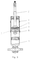
- the hydraulic, controllable vibration damper shown in Figure 1 consists essentially of a damper cylinder 1, which is closed by a guide lock 5, a damper piston 3 connected to a piston rod 2 and a cover 4 made of non-magnetizable material connected to the piston rod 2.
- a damper cylinder 1 In the damper cylinder 1 there are two working spaces, which are separated by the separating piston 6 from a gas-filled compensation space, which serves to compensate for the increase or decrease in volume in the hydraulic working space by the retracting or extending volume of the piston rod 2.
- Above the separating piston 6 is the damper piston 3, firmly connected to the movable piston rod 2, which slides through the guide closure 5 and is sealed by a seal.
- the cover 4 made of non-magnetizable material is designed such that it is open on one side and placed over the damper cylinder 1.
- a sensor winding 9 is embedded in the cover 4 and extends over the entire length of the cover 4.
- the length of these measuring windings 7, 8 is small compared to the length of the sensor winding 9, their connections are led separately to the outside.
- the permanent magnet 10 sliding through the sensor and measuring windings was arranged on the guide closure 5. There is an air gap between the permanent magnet 10 and the sensor 9 and measuring windings 7, 8.
- the lower possible extension position is detected in the same way by the lower measuring winding 8.
- the connections of the sensor and measuring windings are separated or routed together to evaluation electronics, not shown.
- Fig. 2 illustrates the structure of the upper part of the sensor winding 9 with the measuring winding 7, the connection 14 of the measuring winding 7 individually and the connection 13 are led together with the upper connection of the sensor winding 9 to the outside. It may also be useful to arrange a non-magnetizable intermediate layer 12 between the guide closure 5 and the permanent magnet 10, which prevents the magnetic force from being weakened by the iron of the damper cylinder.
- the system of sensor and measuring windings is located on the wall of the damper cylinder 1, which is made of non-magnetizable material, and has been coated with a dielectric for protection against external influences. It would also be conceivable to arrange the sensor and measuring windings directly in the wall of the damper cylinder 1.
- the permanent magnet 10 for generating the induction voltage is located on the damper piston 3 or on the lower part of the piston rod 2. Here, too, a voltage proportional to the relative speed is induced in the sensor winding 9 and a detection signal for the end positions of the extension and retraction stroke is induced in the measuring windings 7 and 8 .
- Fig. 4 shows a vibration damper, which is constructed in opposite directions.
- the sensor winding 9 and the measuring windings 7, 8 are located on or in the wall of the damper cylinder 1, which wall is made of non-magnetizable material.
- the permanent magnet 10, which is designed in particular as a ring magnet, was arranged on the cover 4 and is thus connected to the piston rod 2 via it. Due to the same induction principle, a voltage proportional to the relative speed is induced in the sensor winding 9 during a relative movement between the damper cylinder 1 and damper piston 3, and an identification signal for the end positions of the damper piston 3 is generated by the permanent magnet 10 when passing through the measuring winding 7 or 8.
- the damping can be switched to a higher damping value via a control, the damping cylinder slows down on the buffer 11 and the vibration damper is prevented from breaking through.
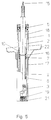
- the working space 18 which is formed by the damper cylinder 1 and is delimited at the lower end by the bottom valve 19 and at the top by the guide lock 5.
- the piston rod 2 which receives the damping piston 3 equipped with controllable or controllable valves in the working space.
- the damper cylinder 1 is surrounded by an outer tube 17, between the two is the compensating chamber 20, which is filled to about half the height with oil, while the working chamber 18 is full of oil.
- the outer tube 17 connects the guide closure 5 to the bottom cap 21 supporting the bottom valve 19 and carries the spring plate 22 which receives a helical spring (not shown).
- the piston rod 2 carries a pull stop 16.
- the sensor winding 9 designed as a cylindrical coil surrounds the piston rod below the train stop 16. Furthermore, two further windings 7, 8 are located on the sensor winding 9 at the lower and upper ends. The length of these windings 7, 8 is small compared to the length of the sensor winding 9, their connections are led separately to the outside.
- the one surrounding the sensor winding 8 and the windings 7, 8, for example A permanent magnet 10 designed as a ring magnet was arranged on the inner wall of the damper cylinder 1. If the damping cylinder 1 consists of non-magnetizable material, the permanent magnet 10 can be arranged between the outer wall of the damper cylinder 1 and the inner wall of the outer tube 17.
- the damper cylinder 1 If the wheel springs out due to a bump in the road, the damper cylinder 1 is pulled down together with the outer tube 17 and the permanent magnet 10 moves downward around the sensor winding 9. Through this movement, he induces a voltage in the sensor winding 9 proportional to the relative speed between the damping piston 3 and the damper cylinder 1. However, when the permanent magnet 10 reaches the end of the sensor winding 9, a voltage is also induced in the winding 7, which is the end position of the permanent magnet and thus signals the permissible end position of the rebound path. The permissible end position of the deflection path is indicated by the winding 8.
- the suspension strut in FIG. 6 has a similar structure to the suspension strut in FIG. 5.
- the piston rod 2 was here made of non-magnetizable material, for example non-magnetizable chromium-nickel steel, and the sensor winding 9 with the windings 7, 8 was arranged axially in the hollow piston rod 2 for detecting the end positions of the inward and outward stroke.
- the connections of the windings are led to the outside together with the connections 24 of the controllable solenoid valve 23 in the hollow piston rod.
- the permanent magnet 10 for generating the induction voltage is also located here on the inner wall of the damper cylinder 1.
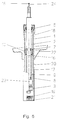
- Fig. 7 shows a shock absorber, which is constructed in opposite directions.
- the sensor winding 9 and the windings 7, 8 for detecting the inward and outward stroke are located on the outer wall of the damper cylinder 1, which is made of non-magnetizable material, it being conceivable to also arrange the windings on the inner wall of the outer tube 17.
- the connections 10 of the windings were led to the outside in the compensation space 20 and with a multipole plug 25 arranged in the guide lock 5 connected.
- sensing the relative speed and the end positions of the inward and outward stroke are to increase the number of turns per unit length at the lower and upper ends of the sensor winding 9, it being possible to lay the turns in multiple layers or denser and to lead the connections of this partial winding separately to the outside.
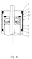
- the hydraulic vibration damper shown in detail in Fig. 8 consists essentially of a damping cylinder 1, which is closed by a guide lock 5, a guided in the damper cylinder 1, made of steel piston rod 2, which carries a not shown damping piston at its lower end, and a cover 4 which is slipped over the damping cylinder 1 and is open on one side.
- the sensor which works very precisely and is integrated in the vibration damper, for measuring the relative speed and / or the piston position in the damper cylinder 1, consists of a radial to the piston rod 2
- Polarized permanent magnet 10 designed as a ring magnet, which is magnetically separated from the damper cylinder 1, which is usually made of steel, by a disk 26 made of non-ferromagnetic material, for example aluminum.
- the permanent magnet 10 can then be integrated in the guide lock 5.
- the damper cylinder 1 moves relative to the piston rod 2 and thus to the sensor winding 9 and the measuring windings 7, 8, which is connected to it due to a bump in the road, the magnetic field of the permanent magnet 10 in the sensor winding 9 induces a voltage due to the closed magnetic circuit which is formed by the radially polarized permanent magnet, the piston rod and the cover, which is very precisely proportional to the relative speed of the vehicle body and axle. An exact signal for detecting the end positions of the damping piston 3 is thus obtained in the measuring windings 7, 8.
- Magnetic stray fluxes which can lead to an inaccuracy of the measurement result, do not occur.
Landscapes
- Engineering & Computer Science (AREA)
- General Engineering & Computer Science (AREA)
- Mechanical Engineering (AREA)
- Physics & Mathematics (AREA)
- General Physics & Mathematics (AREA)
- Fluid-Damping Devices (AREA)
- Measurement Of Length, Angles, Or The Like Using Electric Or Magnetic Means (AREA)
- Vehicle Body Suspensions (AREA)
Applications Claiming Priority (6)
| Application Number | Priority Date | Filing Date | Title |
|---|---|---|---|
| DE4036704 | 1990-11-17 | ||
| DE19904036704 DE4036704A1 (de) | 1990-11-17 | 1990-11-17 | Sensor in einem schwingungsdaempfer fuer kraftfahrzeuge |
| DE19914107290 DE4107290C1 (fr) | 1991-03-07 | 1991-03-07 | |
| DE4107290 | 1991-03-07 | ||
| DE4126586 | 1991-08-12 | ||
| DE4126586A DE4126586A1 (de) | 1991-08-12 | 1991-08-12 | Sensor in einem schwingungsdaempfer fuer kraftfahrzeuge |
Publications (2)
| Publication Number | Publication Date |
|---|---|
| EP0486848A1 true EP0486848A1 (fr) | 1992-05-27 |
| EP0486848B1 EP0486848B1 (fr) | 1997-06-04 |
Family
ID=27201905
Family Applications (1)
| Application Number | Title | Priority Date | Filing Date |
|---|---|---|---|
| EP91118384A Expired - Lifetime EP0486848B1 (fr) | 1990-11-17 | 1991-10-29 | Capteur de position ou de vitesse relative entre un cylindre d'amortisseur et un piston se déplaçant dans ce cylindre |
Country Status (6)
| Country | Link |
|---|---|
| US (1) | US5233293A (fr) |
| EP (1) | EP0486848B1 (fr) |
| JP (1) | JPH04266633A (fr) |
| KR (1) | KR920010287A (fr) |
| DE (1) | DE59108738D1 (fr) |
| ES (1) | ES2032189T3 (fr) |
Cited By (10)
| Publication number | Priority date | Publication date | Assignee | Title |
|---|---|---|---|---|
| WO1997030862A1 (fr) * | 1996-02-24 | 1997-08-28 | Daimler-Benz Aktiengesellschaft | Amortisseur de vibrations telescopique entre la carrosserie et l'element de guidage d'une roue d'un vehicule automobile |
| EP0530475B1 (fr) * | 1991-08-12 | 1997-10-01 | Krupp Bilstein GmbH | Capteur dans un amortisseur pour véhicules à moteur |
| WO1999025989A3 (fr) * | 1997-11-14 | 1999-09-02 | K2 Bike Inc | Amortisseur a omission variable de la fonction d'amortissement |
| EP0981456A1 (fr) * | 1997-05-15 | 2000-03-01 | K2 Bike Inc. | Amortisseurs piezo-electriques |
| EP1539514A4 (fr) * | 2002-08-21 | 2005-12-21 | Delphi Tech Inc | Ensemble amortisseur a piston et sous-ensemble tuyau flexible dotes d'un capteur de vitesse |
| CN105459752A (zh) * | 2014-09-03 | 2016-04-06 | 荣成华泰汽车有限公司 | 车高调整装置 |
| WO2018178287A1 (fr) * | 2017-03-31 | 2018-10-04 | Miro Gudzulic | Dispositif amortisseur à ressort, notamment pour un véhicule |
| AT520496A1 (de) * | 2017-09-27 | 2019-04-15 | Siemens Ag Oesterreich | Dämpfungsvorrichtung |
| WO2019149344A1 (fr) * | 2018-01-31 | 2019-08-08 | HELLA GmbH & Co. KGaA | Ensemble amortisseur |
| DE102021213764A1 (de) | 2021-12-03 | 2023-06-07 | Zf Friedrichshafen Ag | Dämpfervorrichtung mit einem aufsteckbaren Sensorelement sowie Verfahren zur Montage des Sensorelements |
Families Citing this family (51)
| Publication number | Priority date | Publication date | Assignee | Title |
|---|---|---|---|---|
| DE9404164U1 (de) * | 1993-05-27 | 1994-05-19 | Fa. Hermann Heye, 31683 Obernkirchen | Wegaufnehmer für den Positionsnachweis eines Preßstempels |
| US5438261A (en) * | 1994-02-16 | 1995-08-01 | Caterpillar Inc. | Inductive sensing apparatus for a hydraulic cylinder |
| US5497804A (en) * | 1994-06-27 | 1996-03-12 | Caterpillar Inc. | Integral position sensing apparatus for a hydraulic directional valve |
| US5952823A (en) * | 1996-03-22 | 1999-09-14 | Mts Systems Corporation | Magnetostrictive linear displacement transducer for a shock absorber |
| DE19648335C2 (de) * | 1996-11-22 | 2000-05-25 | Daimler Chrysler Ag | Anordnung zur Positionsmessung |
| US6142059A (en) * | 1996-11-27 | 2000-11-07 | Case Corporation | Method and apparatus for sensing the orientation of a mechanical actuator |
| US5977778A (en) * | 1996-11-27 | 1999-11-02 | Case Corporation | Method and apparatus for sensing piston position |
| US5901633A (en) * | 1996-11-27 | 1999-05-11 | Case Corporation | Method and apparatus for sensing piston position using a dipstick assembly |
| DE19716608A1 (de) * | 1997-04-21 | 1998-10-22 | Kloeckner Moeller Gmbh | Sensorvorrichtung zur induktiven Geschwindigkeitsmessung longitudinal beweglicher Teile und elektromagnetisches Schaltgerät mit einer Sensorvorrichtung zur induktiven Geschwindigkeitsmessung |
| US6005395A (en) * | 1997-11-12 | 1999-12-21 | Case Corporation | Method and apparatus for sensing piston position |
| US7290476B1 (en) | 1998-10-20 | 2007-11-06 | Control Products, Inc. | Precision sensor for a hydraulic cylinder |
| DE19913050A1 (de) * | 1999-03-23 | 2000-09-28 | Fev Motorentech Gmbh | Verfahren zur Erfassung der Position und/oder Bewegungsgeschwindigkeit eines zwischen zwei Schaltstellungen hin und her bewegbaren Stellelements |
| US6401883B1 (en) | 1999-09-22 | 2002-06-11 | Mts Systems Corporation | Vehicle suspension strut having a continuous position sensor |
| US20010037724A1 (en) | 2000-03-08 | 2001-11-08 | Schumacher Mark S. | System for controlling hydraulic actuator |
| WO2001066955A2 (fr) | 2000-03-08 | 2001-09-13 | Rosemount Inc. | Debitmetre bidirectionnel a pression differentielle |
| US20010037689A1 (en) * | 2000-03-08 | 2001-11-08 | Krouth Terrance F. | Hydraulic actuator piston measurement apparatus and method |
| WO2001066954A2 (fr) * | 2000-03-08 | 2001-09-13 | Rosemount Inc. | Dispositif de mesure de la position d'un piston |
| US6588313B2 (en) | 2001-05-16 | 2003-07-08 | Rosemont Inc. | Hydraulic piston position sensor |
| US7093361B2 (en) * | 2002-01-23 | 2006-08-22 | Control Products, Inc. | Method of assembling an actuator with an internal sensor |
| EP1375205B1 (fr) * | 2002-06-20 | 2006-08-16 | Tyco Electronics AMP GmbH | Capteur pour la détection du mouvement relatif de deux pièces |
| US20040090020A1 (en) * | 2002-11-08 | 2004-05-13 | Arctic Cat, Inc. | Electronically controlled active suspension damper |
| US6722261B1 (en) | 2002-12-11 | 2004-04-20 | Rosemount Inc. | Hydraulic piston position sensor signal processing |
| US6722260B1 (en) | 2002-12-11 | 2004-04-20 | Rosemount Inc. | Hydraulic piston position sensor |
| EP3249154A1 (fr) * | 2003-11-18 | 2017-11-29 | Halliburton Energy Services Inc. | Système d'outil d'un environnement à haute température et procédé |
| US7308975B2 (en) * | 2003-12-05 | 2007-12-18 | Delphi Technologies, Inc. | Velocity sensing system for a damper |
| CA2471982A1 (fr) * | 2004-04-20 | 2005-10-20 | Eldesco Corporation | Detecteur de vitesse de piston |
| US7609055B2 (en) * | 2004-07-21 | 2009-10-27 | Control Products, Inc. | Position sensing device and method |
| US7300289B2 (en) * | 2005-09-30 | 2007-11-27 | Control Products Inc. | Electrical cordset having connector with integral signal conditioning circuitry |
| WO2008074024A2 (fr) * | 2006-12-13 | 2008-06-19 | Stoneridge Control Devices, Inc. | Capteur de position de cylindre et cylindre incorporant celui-ci |
| US7654370B2 (en) * | 2007-02-02 | 2010-02-02 | Arvin Technologies, Inc. | Shock absorber with integrated position sensor |
| DE102007028827A1 (de) * | 2007-06-20 | 2009-02-19 | Stabilus Gmbh | Kolben-Zylinderaggregat |
| DE102008010247A1 (de) * | 2008-01-16 | 2009-07-23 | Stabilus Gmbh | Kolben-Zylinderaggregat |
| CN102084445A (zh) * | 2008-05-19 | 2011-06-01 | 石通瑞吉控制装置公司 | 汽缸位置传感器和包括所述传感器的汽缸 |
| DE102008035971B3 (de) * | 2008-08-01 | 2009-09-24 | Stabilus Gmbh | Verstellelement |
| KR101037347B1 (ko) * | 2008-12-31 | 2011-05-26 | 한국항공우주연구원 | 항공기 속도계 점검 장치 및 방법 |
| DE102011075310A1 (de) * | 2011-05-05 | 2012-11-08 | Putzmeister Engineering Gmbh | Fahrbare Arbeitsmaschine mit Abstützvorrichtung |
| US10442065B2 (en) | 2011-05-23 | 2019-10-15 | Illinois Tool Works Inc. | Stud miss indicator for fastener driving tool |
| US9605952B2 (en) | 2012-03-08 | 2017-03-28 | Quality Manufacturing Inc. | Touch sensitive robotic gripper |
| CN104271322B (zh) | 2012-03-08 | 2016-09-21 | 品质制造有限公司 | 触敏机器人抓手 |
| US9381635B2 (en) | 2012-06-05 | 2016-07-05 | Illinois Tool Works Inc. | Fastener-driving tool including a fastening result detector |
| CN104374941A (zh) * | 2014-09-24 | 2015-02-25 | 昆山腾朗电子有限公司 | 一种发动机转速测量装置 |
| US10718359B2 (en) | 2015-08-21 | 2020-07-21 | Quality Manufacturing Inc. | Devices and systems for producing rotational actuation |
| US10030426B2 (en) | 2016-03-28 | 2018-07-24 | Schlage Lock Company Llc | Inductive door position sensor |
| WO2017184994A1 (fr) * | 2016-04-22 | 2017-10-26 | KSR IP Holdings, LLC | Capteur inductif pour amortisseur |
| US10859403B2 (en) * | 2016-06-02 | 2020-12-08 | Koganei Corporation | Position detecting apparatus and actuator |
| DE102018116101A1 (de) * | 2018-07-03 | 2020-01-09 | Ab Elektronik Gmbh | Stoßdämpfer mit Positionssensor |
| JP2022083556A (ja) * | 2020-11-25 | 2022-06-06 | 日立Astemo株式会社 | 緩衝器 |
| BR112023015265A2 (pt) | 2021-01-28 | 2023-11-07 | Scoutcam Ltd | Sistema para monitorar falhas em potencial em uma máquina ou um componente da mesma e método implementado por computador para monitorar uma máquina ou um componente da mesma |
| IL316571A (en) | 2022-04-27 | 2024-12-01 | Odysight Ai Ltd | Monitoring a mechanism or component of a mechanism |
| IL318696A (en) * | 2022-08-01 | 2025-03-01 | Odysight Ai Ltd | Monitoring a spring-loaded mechanism |
| USD1083715S1 (en) * | 2022-12-22 | 2025-07-15 | Jingjing Xu | Linkage hydraulic cylinder |
Citations (8)
| Publication number | Priority date | Publication date | Assignee | Title |
|---|---|---|---|---|
| US4054295A (en) * | 1976-08-16 | 1977-10-18 | General Motors Corporation | Vehicle body support and leveler device |
| EP0039181A1 (fr) * | 1980-04-26 | 1981-11-04 | LUCAS INDUSTRIES public limited company | Capteurs de mesure de déplacement et leur utilisation à la détection de déplacements de la suspension de véhicules |
| GB2098007A (en) * | 1981-04-30 | 1982-11-10 | Itt Ind Ltd | Electrical generators |
| DE8524086U1 (de) * | 1984-09-04 | 1985-12-19 | Martonair Ltd., Farnham, Surrey | Mit einem Druckmedium betreibbare Vorrichtung mit einem Sensor, der auf die Bewegung eines beweglichen Elementes der Vorrichtung anspricht |
| FR2608752A1 (fr) * | 1986-12-18 | 1988-06-24 | Boge Ag | Dispositif pour la determination de la course d'un piston |
| FR2612589A1 (fr) * | 1987-03-20 | 1988-09-23 | Tokico Ltd | Amortisseur hydraulique |
| US4949573A (en) * | 1989-11-13 | 1990-08-21 | Lord Corporation | Velocity transducer for vehicle suspension system |
| DE3909190C1 (fr) * | 1989-03-21 | 1990-08-30 | August Bilstein Gmbh & Co Kg, 5828 Ennepetal, De |
Family Cites Families (9)
| Publication number | Priority date | Publication date | Assignee | Title |
|---|---|---|---|---|
| US3215932A (en) * | 1960-10-21 | 1965-11-02 | Samuel E Sims | Method for projectile velocity measurement |
| SU815630A1 (ru) * | 1976-04-09 | 1981-03-23 | Предприятие П/Я Г-4781 | Датчик положени перемещающегос ТЕлА |
| DE2620134C2 (de) * | 1976-05-07 | 1986-01-02 | Robert Bosch Gmbh, 7000 Stuttgart | Einrichtung zur Lageerkennung von beweglichen Körpern |
| DE2911768C2 (de) * | 1979-03-26 | 1983-01-20 | F & O Electronic Systems GmbH & Co, 6901 Neckarsteinach | Regelbarer Stoßdämpfer, insbesondere für Kraftfahrzeuge |
| US4385297A (en) * | 1980-01-14 | 1983-05-24 | Schmitt Wilhelm E | Arrangement for sensing proximity of a reciprocating member |
| US4455555A (en) * | 1980-10-06 | 1984-06-19 | Deere & Company | Control transducer |
| JPS57203913A (en) * | 1981-06-10 | 1982-12-14 | Fujitsu Ltd | Rotation detector |
| SU1029000A1 (ru) * | 1981-12-23 | 1983-07-15 | Куйбышевский ордена Трудового Красного Знамени политехнический институт им.В.В.Куйбышева | Дифференциально-трансформаторный датчик линейных перемещений |
| DE3430045C2 (de) * | 1984-08-16 | 1986-07-17 | Boge Gmbh, 5208 Eitorf | Vorrichtung zur Wegbestimmung eines Kolbens |
-
1991
- 1991-10-29 EP EP91118384A patent/EP0486848B1/fr not_active Expired - Lifetime
- 1991-10-29 ES ES91118384T patent/ES2032189T3/es not_active Expired - Lifetime
- 1991-10-29 DE DE59108738T patent/DE59108738D1/de not_active Expired - Fee Related
- 1991-11-12 JP JP3295456A patent/JPH04266633A/ja active Pending
- 1991-11-15 US US07/792,424 patent/US5233293A/en not_active Expired - Lifetime
- 1991-11-15 KR KR1019910020348A patent/KR920010287A/ko not_active Withdrawn
Patent Citations (8)
| Publication number | Priority date | Publication date | Assignee | Title |
|---|---|---|---|---|
| US4054295A (en) * | 1976-08-16 | 1977-10-18 | General Motors Corporation | Vehicle body support and leveler device |
| EP0039181A1 (fr) * | 1980-04-26 | 1981-11-04 | LUCAS INDUSTRIES public limited company | Capteurs de mesure de déplacement et leur utilisation à la détection de déplacements de la suspension de véhicules |
| GB2098007A (en) * | 1981-04-30 | 1982-11-10 | Itt Ind Ltd | Electrical generators |
| DE8524086U1 (de) * | 1984-09-04 | 1985-12-19 | Martonair Ltd., Farnham, Surrey | Mit einem Druckmedium betreibbare Vorrichtung mit einem Sensor, der auf die Bewegung eines beweglichen Elementes der Vorrichtung anspricht |
| FR2608752A1 (fr) * | 1986-12-18 | 1988-06-24 | Boge Ag | Dispositif pour la determination de la course d'un piston |
| FR2612589A1 (fr) * | 1987-03-20 | 1988-09-23 | Tokico Ltd | Amortisseur hydraulique |
| DE3909190C1 (fr) * | 1989-03-21 | 1990-08-30 | August Bilstein Gmbh & Co Kg, 5828 Ennepetal, De | |
| US4949573A (en) * | 1989-11-13 | 1990-08-21 | Lord Corporation | Velocity transducer for vehicle suspension system |
Cited By (14)
| Publication number | Priority date | Publication date | Assignee | Title |
|---|---|---|---|---|
| EP0530475B1 (fr) * | 1991-08-12 | 1997-10-01 | Krupp Bilstein GmbH | Capteur dans un amortisseur pour véhicules à moteur |
| WO1997030862A1 (fr) * | 1996-02-24 | 1997-08-28 | Daimler-Benz Aktiengesellschaft | Amortisseur de vibrations telescopique entre la carrosserie et l'element de guidage d'une roue d'un vehicule automobile |
| US6053488A (en) * | 1996-02-24 | 2000-04-25 | Daimlerchrysler Ag | Spring damper device between a wheel and the body of a motor vehicle |
| EP0981456A1 (fr) * | 1997-05-15 | 2000-03-01 | K2 Bike Inc. | Amortisseurs piezo-electriques |
| WO1999025989A3 (fr) * | 1997-11-14 | 1999-09-02 | K2 Bike Inc | Amortisseur a omission variable de la fonction d'amortissement |
| EP1539514A4 (fr) * | 2002-08-21 | 2005-12-21 | Delphi Tech Inc | Ensemble amortisseur a piston et sous-ensemble tuyau flexible dotes d'un capteur de vitesse |
| CN105459752A (zh) * | 2014-09-03 | 2016-04-06 | 荣成华泰汽车有限公司 | 车高调整装置 |
| CN105459752B (zh) * | 2014-09-03 | 2019-06-14 | 荣成华泰汽车有限公司 | 车高调整装置 |
| WO2018178287A1 (fr) * | 2017-03-31 | 2018-10-04 | Miro Gudzulic | Dispositif amortisseur à ressort, notamment pour un véhicule |
| AT520496A1 (de) * | 2017-09-27 | 2019-04-15 | Siemens Ag Oesterreich | Dämpfungsvorrichtung |
| AT520496B1 (de) * | 2017-09-27 | 2022-11-15 | Siemens Ag Oesterreich | Dämpfungsvorrichtung |
| WO2019149344A1 (fr) * | 2018-01-31 | 2019-08-08 | HELLA GmbH & Co. KGaA | Ensemble amortisseur |
| DE102021213764A1 (de) | 2021-12-03 | 2023-06-07 | Zf Friedrichshafen Ag | Dämpfervorrichtung mit einem aufsteckbaren Sensorelement sowie Verfahren zur Montage des Sensorelements |
| WO2023099465A2 (fr) | 2021-12-03 | 2023-06-08 | Zf Friedrichshafen Ag | Dispositif amortisseur comprenant un élément de détection emboîtable et procédé de montage de cet élément de détection |
Also Published As
| Publication number | Publication date |
|---|---|
| KR920010287A (ko) | 1992-06-26 |
| DE59108738D1 (de) | 1997-07-10 |
| ES2032189T3 (es) | 1997-10-01 |
| ES2032189T1 (es) | 1993-01-16 |
| JPH04266633A (ja) | 1992-09-22 |
| EP0486848B1 (fr) | 1997-06-04 |
| US5233293A (en) | 1993-08-03 |
Similar Documents
| Publication | Publication Date | Title |
|---|---|---|
| EP0486848B1 (fr) | Capteur de position ou de vitesse relative entre un cylindre d'amortisseur et un piston se déplaçant dans ce cylindre | |
| US5251729A (en) | Vehicle suspension damper with relative velocity sensor having controlled flux path | |
| EP0509244B1 (fr) | Palpeur et méthode pour mesurer la position d'un piston d'amortissement dans un cylindre d'amortissement d'un amortisseur d'oscillations | |
| DE69013464T2 (de) | Geschwindigkeitswandler für ein Fahrzeugaufhängungssystem. | |
| EP0388671A2 (fr) | Capteur d'amortisseur pour un train semi-activement contrôlé avec capteur de vitesse relative et électronique à cet effet | |
| US4726453A (en) | Self-adjusting single- or twin-tube shock absorber | |
| DE3430045C2 (de) | Vorrichtung zur Wegbestimmung eines Kolbens | |
| DE4030229C2 (de) | Berührungsloser Winkelgeber | |
| DE4244204A1 (de) | Wegmeßsystem für den Einfederweg eines Stoßdämpfers | |
| DE3643290C2 (fr) | ||
| EP0530475B1 (fr) | Capteur dans un amortisseur pour véhicules à moteur | |
| EP0486826B1 (fr) | Procédé de mesure de la vitesse relative et les positions fin de course d'un amortisseur de chocs | |
| DE3420666C2 (fr) | ||
| DE19606990C2 (de) | Teleskopartiger Schwingungsdämpfer zwischen dem Aufbau und dem Führungselement eines Rades eines Kraftfahrzeuges | |
| EP0170897A2 (fr) | Dispositif pour la mesure de la vitesse de rotation | |
| DE68926970T2 (de) | Linearer Weggeber, besonders verwendbar bei hydraulischen und pneumatischen Zylindern | |
| EP0502332B1 (fr) | Jambe de suspension pour le châssis d'un véhicule automobile | |
| DE10017562C1 (de) | Luftfeder mit zwei Endgliedern, zwischen denen ein Abstandssensor angeordnet ist | |
| DE3910597A1 (de) | Schaltungsanordnung und verfahren zur induktiven wegmessung | |
| DE3940819C2 (de) | Aktiver Schwingungsdämpfersensor zur Messung der Relativgeschwindigkeit zwischen Aufbau und Achse | |
| DE3821569C2 (fr) | ||
| DE4036704C2 (fr) | ||
| DE4107290C1 (fr) | ||
| EP0120900B1 (fr) | Dispositif inductif de mesure de la distance parcourue | |
| DE3442408A1 (de) | Niveauregeleinrichtung |
Legal Events
| Date | Code | Title | Description |
|---|---|---|---|
| PUAI | Public reference made under article 153(3) epc to a published international application that has entered the european phase |
Free format text: ORIGINAL CODE: 0009012 |
|
| 17P | Request for examination filed |
Effective date: 19920327 |
|
| AK | Designated contracting states |
Kind code of ref document: A1 Designated state(s): BE DE ES FR GB IT NL SE |
|
| ITCL | It: translation for ep claims filed |
Representative=s name: DE DOMINICIS & MAYER S.R.L. |
|
| GBC | Gb: translation of claims filed (gb section 78(7)/1977) | ||
| EL | Fr: translation of claims filed | ||
| TCNL | Nl: translation of patent claims filed | ||
| REG | Reference to a national code |
Ref country code: ES Ref legal event code: BA2A Ref document number: 2032189 Country of ref document: ES Kind code of ref document: T1 |
|
| 17Q | First examination report despatched |
Effective date: 19951016 |
|
| RAP1 | Party data changed (applicant data changed or rights of an application transferred) |
Owner name: AUGUST BILSTEIN GMBH |
|
| GRAG | Despatch of communication of intention to grant |
Free format text: ORIGINAL CODE: EPIDOS AGRA |
|
| GRAH | Despatch of communication of intention to grant a patent |
Free format text: ORIGINAL CODE: EPIDOS IGRA |
|
| ITF | It: translation for a ep patent filed | ||
| GRAH | Despatch of communication of intention to grant a patent |
Free format text: ORIGINAL CODE: EPIDOS IGRA |
|
| GRAA | (expected) grant |
Free format text: ORIGINAL CODE: 0009210 |
|
| AK | Designated contracting states |
Kind code of ref document: B1 Designated state(s): BE DE ES FR GB IT NL SE |
|
| GBT | Gb: translation of ep patent filed (gb section 77(6)(a)/1977) |
Effective date: 19970606 |
|
| REF | Corresponds to: |
Ref document number: 59108738 Country of ref document: DE Date of ref document: 19970710 |
|
| ET | Fr: translation filed | ||
| RAP2 | Party data changed (patent owner data changed or rights of a patent transferred) |
Owner name: KRUPP BILSTEIN GMBH |
|
| PGFP | Annual fee paid to national office [announced via postgrant information from national office to epo] |
Ref country code: NL Payment date: 19970919 Year of fee payment: 7 |
|
| PGFP | Annual fee paid to national office [announced via postgrant information from national office to epo] |
Ref country code: SE Payment date: 19970925 Year of fee payment: 7 |
|
| NLT2 | Nl: modifications (of names), taken from the european patent patent bulletin |
Owner name: KRUPP BILSTEIN GMBH |
|
| REG | Reference to a national code |
Ref country code: ES Ref legal event code: FG2A Ref document number: 2032189 Country of ref document: ES Kind code of ref document: T3 |
|
| PGFP | Annual fee paid to national office [announced via postgrant information from national office to epo] |
Ref country code: BE Payment date: 19971010 Year of fee payment: 7 |
|
| PGFP | Annual fee paid to national office [announced via postgrant information from national office to epo] |
Ref country code: ES Payment date: 19971021 Year of fee payment: 7 |
|
| PLBE | No opposition filed within time limit |
Free format text: ORIGINAL CODE: 0009261 |
|
| STAA | Information on the status of an ep patent application or granted ep patent |
Free format text: STATUS: NO OPPOSITION FILED WITHIN TIME LIMIT |
|
| 26N | No opposition filed | ||
| PG25 | Lapsed in a contracting state [announced via postgrant information from national office to epo] |
Ref country code: SE Free format text: LAPSE BECAUSE OF NON-PAYMENT OF DUE FEES Effective date: 19981030 Ref country code: ES Free format text: LAPSE BECAUSE OF THE APPLICANT RENOUNCES Effective date: 19981030 |
|
| PG25 | Lapsed in a contracting state [announced via postgrant information from national office to epo] |
Ref country code: BE Free format text: LAPSE BECAUSE OF NON-PAYMENT OF DUE FEES Effective date: 19981031 |
|
| BERE | Be: lapsed |
Owner name: AUGUST BILSTEIN G.M.B.H. Effective date: 19981031 |
|
| PG25 | Lapsed in a contracting state [announced via postgrant information from national office to epo] |
Ref country code: NL Free format text: LAPSE BECAUSE OF NON-PAYMENT OF DUE FEES Effective date: 19990501 |
|
| EUG | Se: european patent has lapsed |
Ref document number: 91118384.6 |
|
| NLV4 | Nl: lapsed or anulled due to non-payment of the annual fee |
Effective date: 19990501 |
|
| REG | Reference to a national code |
Ref country code: ES Ref legal event code: FD2A Effective date: 20001102 |
|
| REG | Reference to a national code |
Ref country code: GB Ref legal event code: IF02 |
|
| PGFP | Annual fee paid to national office [announced via postgrant information from national office to epo] |
Ref country code: DE Payment date: 20051014 Year of fee payment: 15 Ref country code: FR Payment date: 20051014 Year of fee payment: 15 |
|
| PGFP | Annual fee paid to national office [announced via postgrant information from national office to epo] |
Ref country code: GB Payment date: 20051017 Year of fee payment: 15 |
|
| PGFP | Annual fee paid to national office [announced via postgrant information from national office to epo] |
Ref country code: IT Payment date: 20061031 Year of fee payment: 16 |
|
| PG25 | Lapsed in a contracting state [announced via postgrant information from national office to epo] |
Ref country code: DE Free format text: LAPSE BECAUSE OF NON-PAYMENT OF DUE FEES Effective date: 20070501 |
|
| GBPC | Gb: european patent ceased through non-payment of renewal fee |
Effective date: 20061029 |
|
| REG | Reference to a national code |
Ref country code: FR Ref legal event code: ST Effective date: 20070629 |
|
| PG25 | Lapsed in a contracting state [announced via postgrant information from national office to epo] |
Ref country code: GB Free format text: LAPSE BECAUSE OF NON-PAYMENT OF DUE FEES Effective date: 20061029 |
|
| PG25 | Lapsed in a contracting state [announced via postgrant information from national office to epo] |
Ref country code: FR Free format text: LAPSE BECAUSE OF NON-PAYMENT OF DUE FEES Effective date: 20061031 |
|
| PG25 | Lapsed in a contracting state [announced via postgrant information from national office to epo] |
Ref country code: IT Free format text: LAPSE BECAUSE OF NON-PAYMENT OF DUE FEES Effective date: 20071029 |