EP0486887A2 - Picking attachment for a harvester - Google Patents
Picking attachment for a harvester Download PDFInfo
- Publication number
- EP0486887A2 EP0486887A2 EP91118968A EP91118968A EP0486887A2 EP 0486887 A2 EP0486887 A2 EP 0486887A2 EP 91118968 A EP91118968 A EP 91118968A EP 91118968 A EP91118968 A EP 91118968A EP 0486887 A2 EP0486887 A2 EP 0486887A2
- Authority
- EP
- European Patent Office
- Prior art keywords
- picking attachment
- counter
- attachment according
- wings
- roller
- Prior art date
- Legal status (The legal status is an assumption and is not a legal conclusion. Google has not performed a legal analysis and makes no representation as to the accuracy of the status listed.)
- Granted
Links
- 238000003306 harvesting Methods 0.000 claims abstract description 8
- 235000013339 cereals Nutrition 0.000 claims abstract description 4
- 241000196324 Embryophyta Species 0.000 claims description 6
- 244000046127 Sorghum vulgare var. technicum Species 0.000 claims 2
- 239000010902 straw Substances 0.000 claims 1
- 230000003993 interaction Effects 0.000 abstract description 3
- 241000209149 Zea Species 0.000 description 2
- 235000005824 Zea mays ssp. parviglumis Nutrition 0.000 description 2
- 235000002017 Zea mays subsp mays Nutrition 0.000 description 2
- 235000005822 corn Nutrition 0.000 description 2
- 230000000694 effects Effects 0.000 description 2
- 230000013011 mating Effects 0.000 description 2
- 230000006835 compression Effects 0.000 description 1
- 238000007906 compression Methods 0.000 description 1
- 238000005265 energy consumption Methods 0.000 description 1
- 238000005516 engineering process Methods 0.000 description 1
- 239000000835 fiber Substances 0.000 description 1
- 239000000463 material Substances 0.000 description 1
- 239000002245 particle Substances 0.000 description 1
- 230000001105 regulatory effect Effects 0.000 description 1
- 238000004804 winding Methods 0.000 description 1
Images


Classifications
-
- A—HUMAN NECESSITIES
- A01—AGRICULTURE; FORESTRY; ANIMAL HUSBANDRY; HUNTING; TRAPPING; FISHING
- A01D—HARVESTING; MOWING
- A01D45/00—Harvesting of standing crops
- A01D45/02—Harvesting of standing crops of maize, i.e. kernel harvesting
- A01D45/021—Cornheaders
-
- A—HUMAN NECESSITIES
- A01—AGRICULTURE; FORESTRY; ANIMAL HUSBANDRY; HUNTING; TRAPPING; FISHING
- A01D—HARVESTING; MOWING
- A01D45/00—Harvesting of standing crops
- A01D45/02—Harvesting of standing crops of maize, i.e. kernel harvesting
- A01D45/021—Cornheaders
- A01D45/025—Snapping rolls
Definitions
- the invention relates to a header for a harvesting device according to the preamble of the main claim.
- Harvesting devices which are equipped with only one feed rotor, the feed rotor being assigned a partial casing which serves as a counter-holder for the mode of operation of the working edges arranged on the feed rotor.
- the invention has for its object to ensure in a picking attachment that works with two interacting, rotating rollers that the energy consumption is as low as possible and a wide distribution of the stem sections cut by the shredding knife takes place.
- the comminution knives are arranged so deep in the area of the feed rotor that they no longer come into contact with the counter-roller and at the same time cause the pull-down rotor and counter-roller to pull them down and after they have passed through the knives shredded stem pieces can be distributed over a wide area.
- the discharge angle is therefore no longer essentially vertical, but obliquely to the side. Because the comminution knives do not yet engage in the counter roller, the resistance which is inevitably caused by the fibers being attached becomes here avoided.
- the wide ejection of the cut stems is also improved by a cover trough covering the counter-roller downwards, which prevents stem particles or stems from simply falling vertically downwards.
- the feed roller is only provided with simple working edges without slots and that the complex knife design can be omitted.
- the working edges of the feed roller and the wings of the counter roller crushing and / or cutting and / or cutting through the stems of the cereals to be harvested can be achieved.
- knives in the area of the feed rotor and the counter-roller which knives are designed, for example, as driven disc knives or as curved cutting knives and which have the effect that the expenditure of force is reduced and the compression effect is reduced Start of retraction of the stalk is avoided.
- Such knives are known from DE-OS 38 28 358.
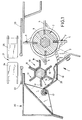
- a picking attachment 1 In the drawings, the part of a picking attachment 1 is shown in section, this picking attachment having a feed rotor 2 which is driven in rotation and is equipped with working edges 3, 4, 5 and 6. These working edges protrude beyond the circumference of the feed rotor 2, and slots 7 are arranged in the projecting parts of the working edges 3 to 6, into which comminution knives 8 protrude.
- the shredding knives 8 are carried by a frame 20, this frame also defining a picking gap 21, the width of which can be regulated by picking plates 22 and 23.
- the corn stalks, not shown in the drawing, are transported by driver fingers 24 and 25, which are carried by feed chains.
- a cover trough 18 is provided on the frame 20, which carries the comminution knives 8 at its lower end and which is pivotably supported by the frame 20 at 17 at its other end. This makes it possible to fold out the comminution knives from the working area of the feed rotor 2.
- a counter roller 10 Associated with the feed rotor 2 is a counter roller 10, which consists of a support shaft 11 comparable to the support shaft 9 of the feed rotor 2, on which vanes 12, 14, 15, 16 and 17 are fastened.
- these wings consist of V- and / or L- and / or U-shaped components.
- the feed rotor 2 and the counter roller 10 are both driven and are connected to one another via a corresponding toothed drive in such a way that they always assume the same position relative to one another, the counter roller 10 rotating faster than the feed rotor 2.
- the cover trough 18 shown in Fig. 1 carries on its inside a cover plate 26, which adapts approximately to the outer envelope of the counter-roller 10, so that the corn stalks supplied by the driving fingers 24 and 25 interact after gripping by the working edges of the feed rotor 2 and with the Wings of the counter roller 10 are guided down to the comminution knives 8. Because of the rotational speed, the stem pieces shredded by the shredding knives 8 are then thrown relatively broadly, so that no swaths form below the area between the feed rotor 2 and the counter roller 10.
- the cover trough 18 is additionally equipped with a counter knife 19 which cooperates with the ends of the counter roller 10 in such a way that it is not possible to wind stems or other weeds in the region of the counter roller.
- the comminution knives 8 are no longer carried by a cover trough, but are arranged relatively directly on the frame 20, in the embodiment shown with the interposition of a carrier 27.
- This carrier 27 carries the knives with the interposition of clamping screws 28, so that after loosening the clamping screws 28, the knives are displaceable and thus adjustable.
- the wings carried by the support shaft 11 are blunt at their ends and interact intermittently with the working edges of the feed rotor 2.
- the wings are designed as L-shaped components, one leg of this L's is pointed and protrudes shorter than the circumference of the support shaft 11 than the other leg.
- the resulting enveloping circles are shown in Fig. 4 and the enveloping circle of the short, tapered leg of the wing of the mating roller 10 are marked with a3 and the enveloping circle of the longer legs of the mating roller 10 are marked with a2.
- the enveloping circle of the feed rotor 2 is also drawn in in FIG. 4 and bears the designation a 1. From Fig.
- FIGS. 1 and 2 another type of fastening of the knives compared to FIGS. 1 and 2 is selected, namely the knives are located on a cover trough 18, but are adjustable in that they are acted upon by a pressure carrier 30 which is fixed by a screw 28.
- the knife 8 can be adjusted by loosening the screw 28.
- the two cooperating work rolls, the feed rotor 2 and the counter roll 10 are set so that the tips of the wings and working edges do not face each other, but the tips of the working edges move along the inside of the pointed wing legs, whereby this sequence of movements prevents plant material from being wrapped around the counter-roller and at the same time cuts and shreds the stems.
- the embodiment of the invention in which the shredding knife is dispensed with is particularly important, so that shredding of the stalks to be harvested is brought about solely by the interaction of the feed roller and the counter roller.
Landscapes
- Life Sciences & Earth Sciences (AREA)
- Environmental Sciences (AREA)
- Harvesting Machines For Specific Crops (AREA)
- Threshing Machine Elements (AREA)
- Manipulator (AREA)
- Harvesting Machines For Root Crops (AREA)
- Harvester Elements (AREA)
Abstract
Die Erfindung bezieht sich auf einen Pflückvorsatz (1) für ein Erntegerät zum Ernten von Körnerfrüchten mit einem Einzugsrotor (2) und einer Gegenwalze (10), wobei die Zerkleinerungsmesser (8), die mit den Arbeitskanten (3-6) des Einzugsrotors (2) zusammenarbeiten und von der Maschine getragen werden ausschließlich mit den Schlitzen des Einzugsrotors (2) zusammenarbeiten, d. h. nicht in die Flügel (12-17) der Gegenwalze (10) eingreifen. Außerdem betrifft die Erfindung einen Pflückvorsatz (1), bei welchem nur ein Einzugsrotor (2) und eine Gegenwalze (10) vorgesehen sind, d. h. auf die Zerkleinerungsmesser (8) wird verzichtet und die Zerkleinerung erfolgt durch das Zusammenwirken von Einzugsrotor (2) und Gegenwalze (10).
Description
Die Erfindung bezieht sich auf einen Pflückvorsatz für ein Erntegerät gemäß dem Oberbegriff des Hauptanspruches.The invention relates to a header for a harvesting device according to the preamble of the main claim.
Es sind Erntegeräte bekannt, die mit nur einem Einzugsrotor ausgerüstet sind, wobei dem Einzugsrotor eine Teilummantelung zugeordnet ist, die als Gegenhalter für die Wirkungsweise der auf dem Einzugsrotor angeordneten Arbeitskanten dient.Harvesting devices are known which are equipped with only one feed rotor, the feed rotor being assigned a partial casing which serves as a counter-holder for the mode of operation of the working edges arranged on the feed rotor.
Obgleich eine solche, nur mit einem einzigen Einzugsrotor arbeitende Einrichtung energietechnisch wesentliche Vorteile aufweist, ist es auch aus der gattungsbildenden DE-39 30 777 A1 bekanntgeworden, als Teilummantelung eine Gegenwalze einzusetzen. Da diese Gegenwalze gegenüber den mit einem Einzugsrotor arbeitenden Einrichtungen einen zusätzlichen Energieaufwand erfordert, ist es von großer Bedeutung dafür Sorge zu tragen, daß dieser Energieaufwand möglichst niedrig gehalten wird.Although such a device, which only works with a single feed rotor, has significant advantages in terms of energy technology, it has also become known from the generic DE-39 30 777 A1 to use a counter roll as a partial covering. Since this counter-roller requires additional energy expenditure compared to the devices working with a feed rotor, it is of great importance to ensure that this energy expenditure is kept as low as possible.
Bei der bekannten, mit zwei sich drehenden Einzugsvorrichtungen arbeitenden Anordnung tritt weiterhin der Nachteil ein, daß die von der Maschine geschnittenen Stengel in einem relativ schmalen Schwad abgelegt werden, so daß ein Verrotten der Stengel erschwert und leichtes Unterpflügen nicht mehr möglich ist.In the known arrangement, which works with two rotating feed devices, there is the further disadvantage that the stalks cut by the machine are deposited in a relatively narrow swath, so that rotting of the stalks is difficult and easy plowing under is no longer possible.
Der Erfindung liegt die Aufgabe zugrunde, bei einem Pflückvorsatz, der mit zwei zusammenwirkenden, drehenden Walzen arbeitet, dafür Sorge zu tragen, daß der Energieaufwand möglichst niedrig ist und eine breitflächige Verteilung der durch die Zerkleinerungsmesser geschnittenen Stengelabschnitte erfolgt.The invention has for its object to ensure in a picking attachment that works with two interacting, rotating rollers that the energy consumption is as low as possible and a wide distribution of the stem sections cut by the shredding knife takes place.
Diese der Erfindung zugrundeliegende Aufgabe wird durch die Lehre des Hauptanspruches gelöst.This object on which the invention is based is achieved by the teaching of the main claim.
Vorteilhafte Ausgestaltungen sind in den Unteransprüchen erläutert.Advantageous configurations are explained in the subclaims.
Mit anderen Worten ausgedrückt wird gemäß der Erfindung vorgeschlagen, daß die Zerkleinerungsmesser so tief im Bereich des Einzugsrotors angeordnet werden, daß sie mit der Gegenwalze nicht mehr in Kontakt kommen und gleichzeitig bewirken, daß die durch Einzugsrotor und Gegenwalze nach unten gezogenen und nach Durchlaufen der Messer zerkleinerten Stengelstückchen breitflächig verteilt werden. Der Abwurfwinkel ist also nicht mehr im wesentlichen vertikal ausgerichtet, sondern schräg zur Seite. Dadurch, daß die Zerkleinerungsmesser nicht noch in die Gegenwalze eingreifen, wird der hier durch Anhängen der Fasern zwangsläufig bedingte Widerstand vermieden.In other words, it is proposed according to the invention that the comminution knives are arranged so deep in the area of the feed rotor that they no longer come into contact with the counter-roller and at the same time cause the pull-down rotor and counter-roller to pull them down and after they have passed through the knives shredded stem pieces can be distributed over a wide area. The discharge angle is therefore no longer essentially vertical, but obliquely to the side. Because the comminution knives do not yet engage in the counter roller, the resistance which is inevitably caused by the fibers being attached becomes here avoided.
Um ein Wickeln der Stengel im Bereich der Gegenwalze zu vermeiden, wird gemäß der Erfindung u. a. auch vorgeschlagen, daß Gegenmesser vorgesehen sind, die mit den Flügeln der Gegenwalze zusammenwirken.In order to avoid winding the stems in the area of the counter roller, according to the invention u. a. also proposed that counter knives are provided which cooperate with the wings of the counter roller.
Das breite Auswerfen der geschnittenen Stengel wird auch durch eine die Gegenwalze nach unten hin abdeckende Abdeckwanne verbessert, die verhindert, daß Stengelteilchen oder Stengel einfach vertikal nach unten hin durchfallen können.The wide ejection of the cut stems is also improved by a cover trough covering the counter-roller downwards, which prevents stem particles or stems from simply falling vertically downwards.
Gemäß der Erfindung ist es auch möglich, nur mit einer Einzugswalze und einer Gegenwalze ohne den Einsatz der Zerkleinerungsmesser zu arbeiten. Hierdurch ist es möglich, daß die Einzugswalze nur mit einfachen Arbeitskanten ohne Schlitze versehen wird und daß die aufwendige Messergestaltung wegfallen kann. Durch das Zusammenwirken der Arbeitskanten der Einzugswalze und der Flügel der Gegenwalze kann ein Quetschen und/oder Einschneiden und/oder Durchschneiden der Stengel der zu erntenden Körnerfrüchte erreicht werden.According to the invention, it is also possible to work with only one feed roller and one counter roller without the use of the comminution knives. This makes it possible that the feed roller is only provided with simple working edges without slots and that the complex knife design can be omitted. Through the interaction of the working edges of the feed roller and the wings of the counter roller, crushing and / or cutting and / or cutting through the stems of the cereals to be harvested can be achieved.
Schließlich ist es gemäß der Erfindung auch zusätzlich zu den in den Zeichnungen dargestellten Ausführungsformen möglich, im Bereich des Einzugsrotors und der Gegenwalze Messer vorzusehen, die beispielsweise als angetriebene Scheibenmesser oder als gewölbte Schneidmesser ausgebildet sind und die bewirken, daß der Kraftaufwand verringert und der Staucheffekt beim Beginn des Einzugs der Stengel vermieden wird. Solche Messer sind aus der DE-OS 38 28 358 bekannt.Finally, according to the invention, it is also possible, in addition to the embodiments shown in the drawings, to provide knives in the area of the feed rotor and the counter-roller, which knives are designed, for example, as driven disc knives or as curved cutting knives and which have the effect that the expenditure of force is reduced and the compression effect is reduced Start of retraction of the stalk is avoided. Such knives are known from DE-OS 38 28 358.
Ausführungsbeispiele der Erfindung werden nachfolgend anhand der Zeichnungen erläutert. Die Zeichnungen zeigen dabei in
- Fig. 1
- in einer geschnittenen Darstellungsweise eine erste Ausführungsform von Einzugsrotor und Gegenwalze, in
- Fig. 2
- in einer geschnittenen Darstellungsweise eine zweite Ausführungsform von Einzugsrotor und Gegenwalze, in
- Fig. 3
- eine abgeänderte Ausführungsform, wobei insbesondere die Messerstellung geändert wurde, in
- Fig. 4
- eine abgeänderte Ausführungsform mit eingezeichneten Hüllkreisen für den Einzugsrotor und die Gegenwalze und in
- Fig. 5
- eine gegenüber Fig. 4 abgeänderte Ausführungsform.
- Fig. 1
- in a sectional representation of a first embodiment of the feed rotor and counter roll, in
- Fig. 2
- in a sectional representation a second embodiment of the feed rotor and counter roll, in
- Fig. 3
- a modified embodiment, in particular the knife position has been changed in
- Fig. 4
- a modified embodiment with drawn enveloping circles for the feed rotor and the counter roller and in
- Fig. 5
- an embodiment modified from FIG. 4.
In den Zeichnungen ist geschnitten der Teil eines Pflückvorsatzes 1 dargestellt, wobei dieser Pflückvorsatz einen Einzugsrotor 2 aufweist, der umlaufend angetrieben wird und mit Arbeitskanten 3, 4, 5 und 6 ausgerüstet ist. Diese Arbeitskanten stehen über den Umfang des Einzugsrotors 2 vor, und in den vorstehenden Teilen der Arbeitskanten 3 bis 6 sind Schlitze 7 angeordnet, in die Zerkleinerungsmesser 8 hineinragen. Die Zerkleinerungsmesser 8 werden von einem Rahmen 20 getragen, wobei dieser Rahmen außerdem einen Pflückspalt 21 definiert, dessen Weite durch Pflückplatten 22 und 23 regelbar ist. Die in der Zeichnung nicht dargestellten Maisstengel werden von Mitnehmerfingern 24 und 25, die von Einzugsketten getragen werden, transportiert.In the drawings, the part of a picking attachment 1 is shown in section, this picking attachment having a
An dem Rahmen 20 ist bei dem dargestellten Ausführungsbeispiel gemäß Fig. 1 eine Abdeckwanne 18 vorgesehen, die an ihrem unteren Ende die Zerkleinerungsmesser 8 trägt und die an ihrem anderen Ende bei 17 schwenkbar vom Rahmen 20 getragen wird. Hierdurch ist es möglich, die Zerkleinerungsmesser aus dem Arbeitsbereich des Einzugsrotors 2 auszuklappen.1, a
Dem Einzugsrotor 2 zugeordnet ist eine Gegenwalze 10, die aus einer der Tragwelle 9 des Einzugsrotors 2 vergleichbaren Tragwelle 11 besteht, auf der Flügel 12, 14, 15, 16 und 17 befestigt sind. Diese Flügel bestehen bei dem dargestellten Ausführungsbeispiel aus V- und/oder L- und/oder U-förmigen Bauteilen. Der Einzugsrotor 2 und die Gegenwalze 10 werden beide angetrieben und sind über einen entsprechenden Verzahnungstrieb antriebsmäßig so miteinander verbunden, daß sie stets die gleiche Stellung zueinander einnehmen, wobei die Gegenwalze 10 schneller umläuft als der Einzugsrotor 2.Associated with the
Die in Fig. 1 dargestellte Abdeckwanne 18 trägt auf ihrer Innenseite ein Abdeckblech 26, das sich dem äußeren Hüllkreis der Gegenwalze 10 etwa anpaßt, so daß die von den Mitnehmerfingern 24 und 25 zugeführten Maisstengel nach Ergreifen durch die Arbeitskanten des Einzugsrotors 2 zusammenwirken und mit den Flügeln der Gegenwalze 10 nach unten zu den Zerkleinerungsmessern 8 geführt werden. Aufgrund der Umlaufgeschwindigkeit werden die von den Zerkleinerungsmessern 8 zerkleinerten Stengelstückchen dann relativ breit abgeworfen, so daß sich unterhalb des Bereiches zwischen dem Einzugsrotor 2 und der Gegenwalze 10 kein Schwad bildet.The
Bei der Anordnung gemäß Fig. 2 ist die Abdeckwanne 18 zusätzlich mit einem Gegenmesser 19 ausgerüstet, das mit den Enden der Gegenwalze 10 so zusammenwirkt, daß ein Wickeln von Stengeln oder sonstigem Unkraut im Bereich der Gegenwalze nicht möglich ist.In the arrangement according to FIG. 2, the
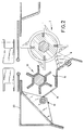
Bei der Ausführungsform gemäß Fig. 3 werden die Zerkleinerungsmesser 8 nicht mehr von einer Abdeckwanne getragen, sondern sind relativ unmittelbar an dem Rahmen 20 angeordnet, und zwar bei dem dargestellten Ausführungsbeispiel unter Zwischenschaltung eines Trägers 27. Dieser Träger 27 trägt die Messer unter Zwischenschaltung von Klemmschrauben 28, so daß nach Lösen der Klemmschrauben 28 die Messer verschiebbar und damit einstellbar sind. Bei dem in Fig. 3 dargestellten Ausführungsbeispiel sind die von der Tragwelle 11 getragenen Flügel an ihren Enden stumpf ausgebildet und wirken intermittierend mit den Arbeitskanten des Einzugsrotors 2 zusammen.In the embodiment according to FIG. 3, the
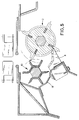
Bei dem in Fig. 4 dargestellten Ausführungsbeispiel sind die Flügel als L-förmige Bauteile ausgebildet, wobei ein Schenkel dieses L's angespitzt ausgebildet ist und kürzer über den Umfang der Tragwelle 11 vorsteht als der andere Schenkel. Die hierdurch bedingten Hüllkreise sind in Fig. 4 eingezeichnet und der Hüllkreis des kurzen, angespitzten Schenkels der Flügel der Gegenwalze 10 sind mit a₃ und der Hüllkreis der längeren Schenkel der Gegenwalze 10 sind mit a₂ eingezeichnet. Zusätzlich ist in Fig. 4 der Hüllkreis des Einzugsrotors 2 ebenfalls eingezeichnet und trägt die Bezeichnung a₁. Aus Fig. 4 wird ersichtlich, daß beim Umlauf von Gegenwalze 10 und Einzugsrotor 2 die Spitzen der Arbeitskanten mit den Spitzen der Flügel nicht in Berührung kommen, aber sich so gegenüberstehen, daß ein kleiner Zwischenraum zwischen den Spitzen gebildet ist, wobei in diesem Zwischenraum der zu erntende Stengel zerquetscht oder zerschnitten wird. Das endgültige Zerschneiden der Stengel erfolgt dann durch die relativ tief unter der Gegenwalze 10 angeordneten Messer 8.In the embodiment shown in Fig. 4, the wings are designed as L-shaped components, one leg of this L's is pointed and protrudes shorter than the circumference of the
Auch bei der Darstellung gemäß Fig. 4 ist eine andere Befestigungsart der Messer gegenüber den Fig. 1 und 2 gewählt, nämlich die Messer befinden sich zwar an einer Abdeckwanne 18, aber sind verstellbar dadurch gelagert, daß sie von einem Druckträger 30 beaufschlagt werden, der durch eine Schraube 28 festgelegt ist. Auch hier kann durch Lösen der Schraube 28 das Messer 8 eingestellt werden.4, another type of fastening of the knives compared to FIGS. 1 and 2 is selected, namely the knives are located on a
Bei der in Fig. 5 dargestellten Ausführungsform sind die beiden zusammenwirkenden Arbeitswalzen, der Einzugsrotor 2 und die Gegenwalze 10 so eingestellt, daß sich nicht die Spitzen von Flügeln und Arbeitskanten gegenüberstehen, sondern die Spitzen der Arbeitskanten bewegen sich an der Innenseite der angespitzten Flügelschenkel entlang, wodurch durch diesen Bewegungsablauf ein Wickeln von Pflanzenmaterial im Bereich der Gegenwalze vermieden wird und gleichzeitig ein Einschneiden und Zerkleinern der Stengel bewirkt wird.In the embodiment shown in Fig. 5, the two cooperating work rolls, the
Durch die im vorausgehenden beschriebenen Anordnungen wird erreicht, daß der Abwurf der zerkleinerten Stengel stärker zur Seite und sehr breitflächig erfolgt, so daß ein leichtes Verrotten und Unterpflügen möglich ist. Die Messer stehen so tief, daß sie nicht mit der Gegenwalze in Kontakt kommen, so daß kein Einziehen von Pflanzenresten in die sonst erforderlichen Schlitze der Pflüge möglich ist. Hierdurch wird jede Reibung und Verschleiß vermieden.The arrangements described above ensure that the shredded stalks are thrown off to the side and over a very large area, so that easy rotting and plowing is possible. The knives are so deep that they do not come into contact with the counter roller, so that no plant residues are drawn into the otherwise necessary plow slots are possible. This avoids any friction and wear.
Während im voraufgehenden, insbesondere anhand der Figuren, verschiedene Ausführungsformen beschrieben und erläutert wurden, ist es im Rahmen der Erfindung liegend, daß die einzelnen Teilmerkmale der Ausführungsformen miteinander vermischt und unterschiedlich kombiniert werden können.While various embodiments have been described and explained in the preceding, in particular with reference to the figures, it is within the scope of the invention that the individual partial features of the embodiments can be mixed with one another and combined differently.
Besonders wesentlich ist die Ausführungsform der Erfindung, bei welcher auf die Zerkleinerungsmesser verzichtet wird, so daß allein durch das Zusammenwirken von Einzugswalze und Gegenwalze ein Zerkleinern der zu erntenden Stengel herbeigeführt wird.The embodiment of the invention in which the shredding knife is dispensed with is particularly important, so that shredding of the stalks to be harvested is brought about solely by the interaction of the feed roller and the counter roller.
Claims (21)
Applications Claiming Priority (2)
| Application Number | Priority Date | Filing Date | Title |
|---|---|---|---|
| DE4036717A DE4036717A1 (en) | 1990-11-17 | 1990-11-17 | PICKING HEADER FOR A HARVEST |
| DE4036717 | 1990-11-17 |
Publications (3)
| Publication Number | Publication Date |
|---|---|
| EP0486887A2 true EP0486887A2 (en) | 1992-05-27 |
| EP0486887A3 EP0486887A3 (en) | 1993-04-21 |
| EP0486887B1 EP0486887B1 (en) | 1995-03-01 |
Family
ID=6418479
Family Applications (1)
| Application Number | Title | Priority Date | Filing Date |
|---|---|---|---|
| EP91118968A Expired - Lifetime EP0486887B1 (en) | 1990-11-17 | 1991-11-07 | Picking attachment for a harvester |
Country Status (4)
| Country | Link |
|---|---|
| US (1) | US5269126A (en) |
| EP (1) | EP0486887B1 (en) |
| AT (1) | ATE118965T1 (en) |
| DE (2) | DE4036717A1 (en) |
Cited By (9)
| Publication number | Priority date | Publication date | Assignee | Title |
|---|---|---|---|---|
| WO1995017807A1 (en) * | 1993-12-27 | 1995-07-06 | Carl Geringhoff Gmbh & Co. Kg | Crop-harvester cutter head |
| EP1040746A1 (en) | 1999-03-30 | 2000-10-04 | Claas Saulgau Gmbh | Device for harvesting fruit on stalks |
| DE102005050470B3 (en) * | 2005-10-21 | 2006-12-14 | Carl Geringhoff Gmbh & Co. Kg | Pick up head for harvester has pair of vaned rotors with gaps in vanes to receive discs on comminuting shaft for crop |
| CN103843532A (en) * | 2014-02-28 | 2014-06-11 | 陈永政 | Corn harvesting machine header |
| CN104429383A (en) * | 2014-11-24 | 2015-03-25 | 郑宇虎 | Cornstalk row-to-row smashing device |
| CN105723914A (en) * | 2016-04-25 | 2016-07-06 | 河南田冠农业机械制造有限公司 | Corn harvester cutting knife assembly with adjustable fixed knife |
| CN107172966A (en) * | 2017-05-25 | 2017-09-19 | 韩登银 | A kind of cotton stem pulverization compressor device people |
| WO2020025236A1 (en) * | 2018-08-03 | 2020-02-06 | Carl Geringhoff Gmbh & Co. Kg | Attachment for harvesting stalk-like stem crops |
| EP3613271A1 (en) * | 2018-08-22 | 2020-02-26 | Deere & Company | Stalk roll with blade inserts for agricultural combine |
Families Citing this family (23)
| Publication number | Priority date | Publication date | Assignee | Title |
|---|---|---|---|---|
| DE4241949C2 (en) * | 1992-12-12 | 1995-05-24 | Geringhoff Carl Gmbh Co Kg | Picking attachment for a harvesting device |
| US6101800A (en) * | 1998-10-26 | 2000-08-15 | Juraco; Albert F. | Field chopping apparatus |
| US9560804B1 (en) * | 2010-12-15 | 2017-02-07 | Marion Calmer | Stalk roll with flutes defining a recess |
| CA2678444C (en) * | 2007-04-05 | 2012-05-29 | Iowa State University Research Foundation, Inc. | Double shear material chopper |
| US7510472B1 (en) * | 2007-10-29 | 2009-03-31 | Cnh America Llc | Combine harvester residue chopper active counter knife assembly |
| US8864561B2 (en) * | 2009-08-26 | 2014-10-21 | Deere & Company | Harvested crop residue chopper and distribution arrangement for a combine with an impeller blower whose shape conforms to the contour of the straw chopper |
| US10785911B2 (en) | 2011-12-15 | 2020-09-29 | Marion Calmer | Stalk roll with hybrid flute having a sharp edge and two blunt edges |
| US12279558B2 (en) | 2010-12-15 | 2025-04-22 | Calmer Holding Company, Llc | Stalk roll |
| US11071252B2 (en) | 2011-12-15 | 2021-07-27 | Marion Calmer | Stalk roll with multiple flutes of different lengths |
| WO2014085811A1 (en) | 2012-11-30 | 2014-06-05 | Marion Calmer | Narrow row head unit |
| BR112016012603B1 (en) * | 2013-12-06 | 2021-06-29 | S7 Ip Holdings, Llc | HARVEST CORN PLATFORM FOR A HARVEST AND ROW UNIT COMBINATION FOR A HARVEST CORN PLATFORM |
| US10172286B2 (en) | 2016-01-06 | 2019-01-08 | Oxbo International Corporation | Knife rolls with differing lengths |
| WO2018049225A1 (en) * | 2016-09-08 | 2018-03-15 | Marion Calmer | Stalk roll |
| DE102017124322A1 (en) * | 2017-10-18 | 2019-04-18 | Carl Geringhoff Gmbh & Co. Kg | Attachment with picking rotors |
| CN108076869A (en) * | 2018-01-09 | 2018-05-29 | 江苏理工学院 | A kind of petite culture object stalk crasher |
| CN108093897A (en) * | 2018-01-09 | 2018-06-01 | 江苏理工学院 | A kind of novel vertical stalk crasher |
| CN108811789A (en) * | 2018-08-07 | 2018-11-16 | 南京申发冶金机械制造有限公司 | Baler, stalk feeding shredding mechanism and its cutting blade |
| CN109220177A (en) * | 2018-11-12 | 2019-01-18 | 南京申发冶金机械制造有限公司 | The straw chopping apparatus and maize harvesting machine of ear picking bench of corn harvester |
| USD1023700S1 (en) | 2019-02-12 | 2024-04-23 | Calmer Holding Company, Llc | Stalk roll |
| CN109769481A (en) * | 2019-02-20 | 2019-05-21 | 农业农村部南京农业机械化研究所 | A kind of stalk component is adjustable to pick up defeated device |
| US11369062B2 (en) * | 2019-05-15 | 2022-06-28 | Cnh Industrial America Llc | Agricultural baler with intermeshing feed rotors |
| DE102023135749A1 (en) * | 2023-12-19 | 2025-06-26 | Claas Selbstfahrende Erntemaschinen Gmbh | Picking roller unit for a front attachment for harvesting stalked crops |
| CN119344086A (en) * | 2024-12-10 | 2025-01-24 | 河北宗申戈梅利农业机械制造有限公司 | Corn cob diverting device and corn harvester |
Family Cites Families (10)
| Publication number | Priority date | Publication date | Assignee | Title |
|---|---|---|---|---|
| US3863431A (en) * | 1972-05-01 | 1975-02-04 | Sugar Cane Growers Coop | Apparatus for harvesting and cleaning windrowed cane |
| DE3415708A1 (en) * | 1984-04-27 | 1985-10-31 | Biso Bitter Gmbh & Co Kg, 4520 Melle | HARVESTER |
| DE3610141A1 (en) * | 1986-03-26 | 1987-10-01 | Claas Ohg | MAISERNTEGERAET |
| DE3612224C2 (en) * | 1986-04-11 | 1994-11-03 | Claas Ohg | Corn harvester |
| DE3726967C2 (en) * | 1987-08-13 | 1995-08-03 | Claas Ohg | Harvester for harvesting corn or other cereals |
| DE3808324C2 (en) * | 1988-03-12 | 1996-07-11 | Claas Ohg | Harvester for harvesting corn |
| US4845930A (en) * | 1988-05-02 | 1989-07-11 | Byron Enterprises, Inc. | Corn ear cutter machine |
| DE3828358A1 (en) * | 1988-08-20 | 1990-02-22 | Kalverkamp Klemens | PICKING HEADER FOR A HARVEST |
| DE3930777A1 (en) * | 1989-01-16 | 1990-07-19 | Claas Ohg | HARVESTER FOR HARVESTING CORN |
| DE4028468C1 (en) * | 1990-09-07 | 1992-05-27 | Norbert Dipl.-Ing. 6082 Moerfelden-Walldorf De Pick |
-
1990
- 1990-11-17 DE DE4036717A patent/DE4036717A1/en not_active Withdrawn
-
1991
- 1991-11-07 AT AT91118968T patent/ATE118965T1/en not_active IP Right Cessation
- 1991-11-07 DE DE59104774T patent/DE59104774D1/en not_active Expired - Fee Related
- 1991-11-07 EP EP91118968A patent/EP0486887B1/en not_active Expired - Lifetime
-
1992
- 1992-05-05 US US07/878,765 patent/US5269126A/en not_active Expired - Fee Related
Cited By (13)
| Publication number | Priority date | Publication date | Assignee | Title |
|---|---|---|---|---|
| WO1995017807A1 (en) * | 1993-12-27 | 1995-07-06 | Carl Geringhoff Gmbh & Co. Kg | Crop-harvester cutter head |
| US5787696A (en) * | 1993-12-27 | 1998-08-04 | Carl Geringhoff Gmbh & Co. Kg | Picking attachment for a harvester |
| EP1040746A1 (en) | 1999-03-30 | 2000-10-04 | Claas Saulgau Gmbh | Device for harvesting fruit on stalks |
| DE102005050470B3 (en) * | 2005-10-21 | 2006-12-14 | Carl Geringhoff Gmbh & Co. Kg | Pick up head for harvester has pair of vaned rotors with gaps in vanes to receive discs on comminuting shaft for crop |
| CN103843532B (en) * | 2014-02-28 | 2016-02-17 | 陈永政 | A kind of corn harvester |
| CN103843532A (en) * | 2014-02-28 | 2014-06-11 | 陈永政 | Corn harvesting machine header |
| CN104429383A (en) * | 2014-11-24 | 2015-03-25 | 郑宇虎 | Cornstalk row-to-row smashing device |
| CN105723914A (en) * | 2016-04-25 | 2016-07-06 | 河南田冠农业机械制造有限公司 | Corn harvester cutting knife assembly with adjustable fixed knife |
| CN107172966A (en) * | 2017-05-25 | 2017-09-19 | 韩登银 | A kind of cotton stem pulverization compressor device people |
| WO2020025236A1 (en) * | 2018-08-03 | 2020-02-06 | Carl Geringhoff Gmbh & Co. Kg | Attachment for harvesting stalk-like stem crops |
| US11937547B2 (en) | 2018-08-03 | 2024-03-26 | Carl Geringhoff Gmbh & Co. Kg | Attachment for harvesting stalk-like stem crops with meshing picking rotors |
| EP3613271A1 (en) * | 2018-08-22 | 2020-02-26 | Deere & Company | Stalk roll with blade inserts for agricultural combine |
| US10820512B2 (en) | 2018-08-22 | 2020-11-03 | Deere & Company | Stalk roll with blade inserts for agricultural combine |
Also Published As
| Publication number | Publication date |
|---|---|
| ATE118965T1 (en) | 1995-03-15 |
| EP0486887B1 (en) | 1995-03-01 |
| DE59104774D1 (en) | 1995-04-06 |
| DE4036717A1 (en) | 1992-08-20 |
| US5269126A (en) | 1993-12-14 |
| EP0486887A3 (en) | 1993-04-21 |
Similar Documents
| Publication | Publication Date | Title |
|---|---|---|
| EP0486887B1 (en) | Picking attachment for a harvester | |
| EP0685992B1 (en) | Crop-harvester cutter head | |
| DE3302980C2 (en) | ||
| EP0538599B1 (en) | Chopper | |
| EP0415419A2 (en) | Chopper | |
| EP0369440B1 (en) | Process and device for harvesting fruit on stalks | |
| EP1671532B1 (en) | Forage chopping cylinder | |
| EP0135724B1 (en) | Multirow-harvester, especially for maize | |
| DE3234657C2 (en) | ||
| EP1797753B1 (en) | Forage harvester | |
| DD229942A5 (en) | METHOD AND DEVICE FOR CRUSHING PLANT PRODUCTS | |
| DE4202865C2 (en) | mowing machine | |
| WO2014198599A1 (en) | Harvester for mowing stalky crops | |
| EP1000533B1 (en) | Picking device for harvesting cereals | |
| EP0355441B1 (en) | Picking attachment for a harvester | |
| DE102020002342A1 (en) | Mulcher | |
| DD220803A1 (en) | NACHZERKLEINERUNGSEINICHTUNG FOR HAECKSELGUT | |
| DE3844734C2 (en) | Plucking unit for maize harvester | |
| DE10037108A1 (en) | Cutting device to chop up vegetable matter has counter-cutter in form of circumferential cutter of rotatable second circular disk | |
| EP0716802A1 (en) | Corn gathering and picking device | |
| DE102019007585A1 (en) | Row-independent header for harvesting stem-shaped plants with a picking gap that is perpendicular to the direction of travel and runs through the entire header | |
| EP0759268A1 (en) | Method and device for collecting and compacting plant matter | |
| EP3228176B1 (en) | Harvesting machine with a cutting device | |
| EP1782680B1 (en) | Device for crushing vegetable products in the form of green mass or juvenile wood | |
| DE29923382U1 (en) | Picking attachment for a harvesting device |
Legal Events
| Date | Code | Title | Description |
|---|---|---|---|
| PUAI | Public reference made under article 153(3) epc to a published international application that has entered the european phase |
Free format text: ORIGINAL CODE: 0009012 |
|
| AK | Designated contracting states |
Kind code of ref document: A2 Designated state(s): AT BE DE ES FR IT NL |
|
| PUAL | Search report despatched |
Free format text: ORIGINAL CODE: 0009013 |
|
| AK | Designated contracting states |
Kind code of ref document: A3 Designated state(s): AT BE DE ES FR IT NL |
|
| 17P | Request for examination filed |
Effective date: 19930330 |
|
| 17Q | First examination report despatched |
Effective date: 19940707 |
|
| GRAA | (expected) grant |
Free format text: ORIGINAL CODE: 0009210 |
|
| AK | Designated contracting states |
Kind code of ref document: B1 Designated state(s): AT BE DE ES FR IT NL |
|
| PG25 | Lapsed in a contracting state [announced via postgrant information from national office to epo] |
Ref country code: ES Free format text: THE PATENT HAS BEEN ANNULLED BY A DECISION OF A NATIONAL AUTHORITY Effective date: 19950301 |
|
| REF | Corresponds to: |
Ref document number: 118965 Country of ref document: AT Date of ref document: 19950315 Kind code of ref document: T |
|
| RAP4 | Party data changed (patent owner data changed or rights of a patent transferred) |
Owner name: KALVERKAMP, KLEMENS |
|
| REF | Corresponds to: |
Ref document number: 59104774 Country of ref document: DE Date of ref document: 19950406 |
|
| ET | Fr: translation filed | ||
| ITF | It: translation for a ep patent filed | ||
| PLBE | No opposition filed within time limit |
Free format text: ORIGINAL CODE: 0009261 |
|
| STAA | Information on the status of an ep patent application or granted ep patent |
Free format text: STATUS: NO OPPOSITION FILED WITHIN TIME LIMIT |
|
| 26N | No opposition filed | ||
| PGFP | Annual fee paid to national office [announced via postgrant information from national office to epo] |
Ref country code: AT Payment date: 19961129 Year of fee payment: 6 |
|
| PGFP | Annual fee paid to national office [announced via postgrant information from national office to epo] |
Ref country code: NL Payment date: 19961130 Year of fee payment: 6 |
|
| PG25 | Lapsed in a contracting state [announced via postgrant information from national office to epo] |
Ref country code: AT Free format text: LAPSE BECAUSE OF NON-PAYMENT OF DUE FEES Effective date: 19971107 |
|
| PG25 | Lapsed in a contracting state [announced via postgrant information from national office to epo] |
Ref country code: NL Free format text: LAPSE BECAUSE OF NON-PAYMENT OF DUE FEES Effective date: 19980601 |
|
| NLV4 | Nl: lapsed or anulled due to non-payment of the annual fee |
Effective date: 19980601 |
|
| PGFP | Annual fee paid to national office [announced via postgrant information from national office to epo] |
Ref country code: DE Payment date: 19990920 Year of fee payment: 9 |
|
| PGFP | Annual fee paid to national office [announced via postgrant information from national office to epo] |
Ref country code: FR Payment date: 19991029 Year of fee payment: 9 |
|
| PGFP | Annual fee paid to national office [announced via postgrant information from national office to epo] |
Ref country code: BE Payment date: 19991112 Year of fee payment: 9 |
|
| PG25 | Lapsed in a contracting state [announced via postgrant information from national office to epo] |
Ref country code: BE Free format text: LAPSE BECAUSE OF NON-PAYMENT OF DUE FEES Effective date: 20001130 |
|
| BERE | Be: lapsed |
Owner name: KALVERKAMP KLEMENS Effective date: 20001130 |
|
| PG25 | Lapsed in a contracting state [announced via postgrant information from national office to epo] |
Ref country code: FR Free format text: LAPSE BECAUSE OF NON-PAYMENT OF DUE FEES Effective date: 20010731 |
|
| PG25 | Lapsed in a contracting state [announced via postgrant information from national office to epo] |
Ref country code: DE Free format text: LAPSE BECAUSE OF NON-PAYMENT OF DUE FEES Effective date: 20010801 |
|
| REG | Reference to a national code |
Ref country code: FR Ref legal event code: ST |
|
| PG25 | Lapsed in a contracting state [announced via postgrant information from national office to epo] |
Ref country code: IT Free format text: LAPSE BECAUSE OF NON-PAYMENT OF DUE FEES;WARNING: LAPSES OF ITALIAN PATENTS WITH EFFECTIVE DATE BEFORE 2007 MAY HAVE OCCURRED AT ANY TIME BEFORE 2007. THE CORRECT EFFECTIVE DATE MAY BE DIFFERENT FROM THE ONE RECORDED. Effective date: 20051107 |